Level measurement and control in process vessels can be one of the most challenging applications in which to obtain consistently safe and reliable results. Part of this difficulty may be due to the fact that the sizing of the vessel and selection and installation of the level instruments are frequently performed by different people at different times, rather than evaluated holistically as a system.
Level instruments are installed on vessels to provide local indication of the liquid level, automatic level control and alarms to indicate upset conditions so that an operator can respond. They are also used to automatically bring a process to a safe state when safe operating limits are reached. The level-instrument technologies used and how they are installed can adversely affect the usable vessel volume by reducing the span that is visible to the operator and the control system.
This article presents best practices in vessel sizing and level-instrument selection and installation. Practical examples demonstrate the recommended holistic approach.
Vessel sizing
 |
 |
While various methods exist in the chemical process industries (CPI) for sizing vessels, two methods find widespread use.
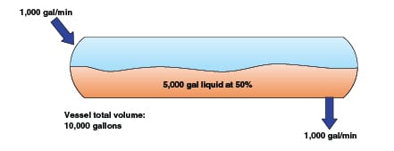
Method 1. One of the most common methods to size vessels is presented in “Chemical Process Equipment – Selection and Design” [ 1]. This method states that the vessel volume is calculated in terms of the number of minutes of flow (or the residence time) on a half-full basis, and that five to ten minutes is adequate for most applications. Fired-heater feed surge drums and the liquid sumps of compressor-suction knockout drums are specific exceptions where more residence time is required. Method 1 is commonly used because the only information needed to size the vessel is the volumetric flowrate and knowledge of the equipment being fed by the vessel. Figure 1 depicts an example of vessel sizing on this basis, using a 1,000 gal/min flowrate and a 5-min residence time.
Method 2 and variants. Another method used to size vessels is presented in “Distillation Operation” [ 2]. This method is presented specifically for distillation reflux drums, but is easily adapted for sizing other types of process vessels by adjusting the residence time requirement to suit the process intent. Rather than assuming the vessel is operating at half-full, it recommends sizing based on the residence time between the high- and low-level operating limits. Method 2 is slightly more complex than Method 1 because it also requires knowledge of the vessel operating limits in order to determine the total vessel volume. Figure 2 depicts an example of vessel sizing on this basis, again using a 1,000 gal/min flowrate and a 5-min residence time.
Other sizing methodologies, which are variants of the second method, may take into account specific hazards that can exist if a vessel runs empty or is overfilled. For example, if a hazard is created for downstream equipment when a vessel runs empty — such as due to vapor blow-through or running the tubes in fired equipment dry — then it may be appropriate to also consider the residence time from the low-level operating limit to empty. Conversely, if a hazard is created when a vessel overfills — such as a compressor suction drum — then considering the residence time from the high-level operating limit to the overfill or liquid-carryover condition can be suitable. In either case, the purpose of the vessel and its operating limits must be thoroughly understood to use these methods.
Vessel sizing best practices. When vessels are sized during conceptual design for the purpose of developing a budgetary or funding-approval estimate, there is generally insufficient information available to define the operating limits. Since cost estimates are typically on the order of ±25 to 50% during these early design phases, Method 1 is suitably accurate and is easy to apply.
When making final vessel-sizing calculations during the definitive estimate phase (typically ±10%), additional information should be taken into consideration in order to ensure that the usable volume is sufficient to perform the vessel’s function. In addition to knowledge of the operating limits required by Method 2, this typically involves information that may not be readily available to the engineers responsible for sizing the vessel, and so often requires involvement of a design team to determine the following:
• What level-instrument technologies will be used
• How the level instruments will be installed
• Alarms and the time required for an operator to respond appropriately before a hazardous situation occurs or an automated system takes action to make the process safe
In many cases these two methods will yield similar results, but spending a small amount of time optimizing the design with some additional knowledge can pay big dividends in how much operating range is actually available in the vessel.
Local level instruments
Level instruments intended for local indication allow visual confirmation of the level for redundancy in operation, as well as for calibration of level transmitters and testing of level switches. Two frequently used types are discussed below.
Gage glasses. A single-section gage glass is a simple and intuitive device for viewing liquid level. One limitation of gage glasses relative to the usable volume of a vessel is that they usually extend 3 in. or more at both the top and the bottom (6 in. total) of the gage, which is not covered by the glass window and therefore should not be considered part of the usable, vessel operating range. Because of the risk of breakage and loss of containment of the process media, multiple overlapping gages (usually of 5-ft or shorter lengths) are often required for taller vessels, which may require more vessel platforms for access to the instrument block, vent and drain valves.
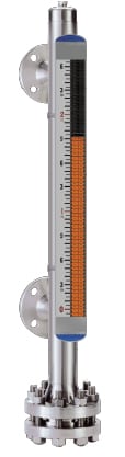 |
Magnetic level gages. Figure 3 depicts a magnetic level gage. A magnetic float is installed inside the chamber, and the indicators change the displayed color as the magnetic field of the float travels. This type of level instrument addresses the limitations associated with gage glasses because there is no loss of visible range between the connection points. Magnetic level gages can measure the entire span.
Glass breakage is not a concern with magnetic level gages, so measuring lengths of ten feet or sometimes more is easily handled in a single gage, which can mean fewer vessel platforms required for access to valves.
Additional installation consider-ations to be aware of are that magnetic level gages require significant clear space below the bottom connection for float removal, and are physically larger and heavier than a gage glass and so may require larger diameter or reinforced process connections to support their weight.
Transmitters and switches
Level transmitters and switches provide a method for the level in the vessel to be read remotely. They are used to provide automatic level control and alarms to indicate upset conditions and trigger operator response. They can also be used to automatically bring the process to a safe state if the operating limits are reached. Many transmitter and switch technologies are available, and no single technology will suit all applications.
The measuring range of a transmitter is typically specified to be the same as or slightly less than (usually 4–6 in.) the measuring range of the local level gage. This allows the output of the transmitter to be directly compared to the visual indicator to check its calibration and ensure it is functioning properly. The transmitter range should rarely exceed the gage visible range, since this makes verifying the high and low limits of the transmitter in situ difficult, if not impossible. Conversely, any vessel volume that is viewable by the local gage but not measurable by the transmitter is generally not available for use in the operating range.
The working operating range of the liquid level should not extend past the alarm points, and by definition cannot extend past the shutdown points.
Typically the vessel percent full as read by the level instrument correlates to percent of level instrument span, and does not equate to percent of actual vessel volume. A vessel strapping table should be developed and used to convert percent level readings to percent of vessel volume. Most modern control systems can be programmed with an equation to convert automatically, if desired.
The alarm and shutdown setpoints for high level generally should be no greater than 90% of the transmitter span. Similarly, the alarm and shutdown setpoints for low level should be no less than 10% of the transmitter span. The reason for this is to ensure that these critical points can be read by the transmitter under all operating conditions.
For example, when using a differential-pressure-style level transmitter, a 10% decrease in the density of the process fluid — such as might occur in vessels containing fluid mixtures of varying composition or temperature — can result in the vessel being completely full (filled above the top transmitter connection), but the transmitter may indicate only 90% output. This is because the weight of the liquid column between the transmitter connections is less than that for which the transmitter was designed, and the liquid above the top connection exerts its weight on both the top and the bottom connections equally, so it does not create a differential pressure to be measured. If the alarm or shutdown setpoint is greater than 90%, the transmitter may be incapable of reading it during process upset conditions when temperature or composition changes affect the liquid density.
The selection of the level technology to be used should include consideration of how the specific physical property of the liquid being measured may change during normal operating or process upset conditions. If the liquid density can change significantly, then differential-pressure-style measurements may not be the best choice. If the electrical conductivity of the liquid can vary, or is extremely low, then technologies that rely on this property, such as radar or capacitance, may not be suitable.
Any shutdown setpoint should generally be preceded by an alarm to alert the operator to take action to bring the process back into control and prevent safe operating limits from being exceeded. The difference between the alarm and shutdown setpoints needs to be adequate for the operator to have response time to identify that an issue exists, then diagnose and correct the problem. The alarm and shutdown setpoints also need to be sufficiently far away from the normal operating level that minor process upsets do not create nuisance alarms.
To ensure that the level-instrument design and the vessel process design are consistent with each other, the drum levels corresponding to low and high alarms and shutdown setpoints should be indicated on the process and instrumentation diagram (P&ID).
Level bridles
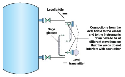
Level bridles are often used as a means to mount multiple level instruments to a single pair of vessel process connections, rather than providing each level instrument with independent connections to the vessel. This is sometimes unavoidable and necessary, especially with existing pressure vessels or high-pressure, thick-walled vessels where the addition of nozzles cannot be cost justified.
Mounting instruments to a level bridle generally requires that the elevations of the process connections (for each instrument to the bridle) be staggered to avoid interference with each other, and this results in a loss of usable vessel volume as the instrument span is narrowed. This consequence can be avoided if each instrument has its own connections to the vessel.
In addition, avoiding the use of level bridles will reduce the total number of welds required, generally reduce the number of valves required to install all the instruments, and will virtually eliminate an interface between the process control and piping design disciplines. All of these factors reduce the complexity and cost of the level-instrument installation.
Level instrument best practices
In order to maximize the volume of a vessel that is usable and within the measurable and controllable limits of the instrumentation, take the steps outlined here. Each of these three steps will add approximately 6 in. to the usable operating range of the liquid, or about 18 in. total.
1. Use magnetic level gages instead of gage glasses where the technology is suitable for the application.
2. Install the level transmitters to measure the entire visible range of the local gage instead of covering a narrower range.
3. Mount each instrument directly to the vessel with its own process connections rather than off a level bridle.
The smaller the size of the vessel, the greater percentage of the total volume these 18 in. to be gained represent, so while important in all cases these best practices are most critical on horizontal vessels, and water boots and other vertical vessels with a short sidewall.
 |
Practical examples
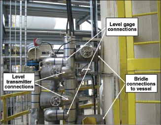
Common practice. Figure 4 depicts a situation where a vertical vessel with dimensions of 8-ft inside diameter (I.D.) by 12-ft tangent-to-tangent height (nominal volume 5,000 gal including the bottom head) is equipped with a level instrument setup that is very commonly encountered in industry. It has a side-mounted level bridle, two overlapping gage glasses, and a level transmitter. Walk around your facility and you’ll probably find a few installations set up just like this. See Figure 5 for a similar example of what you may find.
The vessel was sized on the basis of Method 1. At 50% full, the vessel is designed for 5 min of residence time with 500 gal/min of liquid flow. Now evaluate how the level instruments are installed and what effect this has on the usable volume of the vessel.
The process connections for the level instruments are often approximately 12 in. away from the tangent lines, so in this case with the vessel height of 12 ft, the nozzles would be about 10 ft apart.
By mounting the gage glasses to a level bridle instead of directly to the vessel, about 6 in. of total operating range is lost because the top-most and bottom-most gage connections are staggered to avoid interference with the bridle process connections.
Since gage glasses are used instead of a magnetic level gage, another 6 in. of total operating range is lost because of the difference in visible range of these technologies. Also, the level transmitter is installed so that its connections to the bridle are staggered with those of the gage glasses, meaning another 6 in. of operating range is lost.
Lastly, consider that this vessel has a high level alarm at 90% of the transmitter span and a low level alarm at 10% of the transmitter span. The transmitter span is 8.5 ft, so this equates to another 20 in. of operating range that is lost since the level should not exceed the alarm limits during normal operation.
While this vessel has a height of 12 ft, only the middle 6 ft and 10 in. of the vessel represents usable volume (about 2,600 gal of the total 5,000-gal volume) within the alarm limits of the transmitter. The operating range has been significantly restricted by the types of level instruments used and the installation methods.
Incidentally, doing a quick calculation of the 2,600 gal of usable volume between the alarm points with 500 gal/min of throughput, the residence time of the usable volume is slightly over 5 min. So this is a case where vessel sizing Methods 1 and 2 would both have yielded essentially the same result. By using Method 2 to check final sizing, this confirms that the initial sizing with Method 1 was appropriate and does not need to be revised.
 |
|
Figure 5. This installation is similar to that shown in Figure 4, with a staggering
of the instrument connection elevations |
 |
Compare this result to the same vessel where best practices for level instruments have been applied.
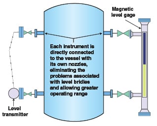
Best practice. Figure 6 depicts the same vertical vessel, but equipped this time with a single, magnetic level gage and a level transmitter, both with their own connections to the vessel rather than using a level bridle.
Again, the process connections for the level instruments are approximately 12 in. away from the tangent lines, so the nozzles would be about 10 ft apart.
Because a magnetic level gage is used and is directly connected to the vessel, the visible range covers the entire 10 ft between the process connections. The level transmitter is installed so its span is the same as that of the level gage, so it can also measure the entire 10-ft span. The alarm limits at 90% and 10% of the transmitter span will result in a loss of 24 in. of operating range.
In this case, the vessel has a height of 12 ft and the middle 8 ft of the vessel represents usable volume (about 3,000 gal of the total 5,000-gal volume) within the alarm limits of the transmitter. The operating range and usable volume have been increased by 15% over the previous case just by changing the types of level instruments used and how they are installed.
Although this vessel is the same size as that in the previous example, this additional 15% usable volume can allow for greater tolerance to a process upset without resulting in an alarm or a shutdown condition simply by allowing the operator and the control system to view and utilize a greater portion of the vessel.
Also important, the total installed cost of this system is expected to be less than that in the previous example, because it requires no bridle piping, fewer valves, fewer total welds (but more shop welds are required for the additional vessel nozzles) and fewer instruments. It also takes up less physical space that might have otherwise increased the access platform size.
Final notes
It is important to consider how a vessel will be instrumented in order to ensure the vessel size is appropriate. Considerations in evaluating the vessel and level instruments holistically should include the following:
• The process intent of the vessel
• Cost-effective vessel design
• Level instrument technology selected and installation method
• Time required for the operator to respond to alarms and regain control before safe operating limits are reached
• Physical access and platforms required to view and maintain the instruments, the block valves, and the vent/drain valves
• Coordination of the level bridle design (if used — not normally recommended) with the instrument installation and physical access requirements
These considerations will often go beyond the information available to just the process and mechanical engineers, and will need to include process control engineers, operators, and piping designers to provide the most safe, reliable, and cost-effective system possible.
Edited by Dorothy Lozowski
References
1. Couper, J.R., Penney, W.R., Fair, J.R., Walas, S.M., “Chemical Process Equipment – Design and Selection,” 3rd ed., Elsevier, 2010.
2. Kister, H.Z., “Distillation Operation”, McGraw-Hill, 1990.
Author

Chad E. Schaffer is an associate process instrumentation and controls engineer in the Process & Industrial Division at Burns & McDonnell (9400 Ward Parkway, Kansas City, MO 64114; Phone: 816-822-3114; Email: cschaffer@burnsmcd.com), an employee-owned engineering and construction management firm. He has implemented projects for clients in the refining, chemicals, biofuels, gas processing and power generation industries. Schaffer is a senior member of AIChE and ISA, a member of the Process Industry Practices (PIP) Process Control Function Team, the ISA 84 working group and the Center for Chemical Process Safety Technical Steering Committee. He received his B.S.Ch.E. from the University of Kansas in 1996, is a registered professional engineer in multiple states, and is a Certified Functional Safety Expert (CFSE).