Off-scale readings from pressure instruments often indicate systematic problems. Diagnostic and other information from these devices can be used to determine root causes
Pressure instruments are widely used in most process plants and facilities. From providing simple indication data points to critical control, pressure measurements are utilized extensively. Most applications only monitor the process variable, namely the pressure reading, often disregarding the wealth of additional available data, and causing these instruments to be overlooked as a source of deeper insight into the process.
But pressure instruments are often the canary in the coalmine because readings outside of expected values — often attributed to drift or other instrument issues — can be caused by human error or a larger, process-related issue. The challenge is how to reliably prevent these issues, and to identify the root cause (Figure 1).

FIGURE 1. Chemical plant problems can often be predicted by correctly interpreting information provided by pressure and other instruments
This article shows how diagnostics and other information supplied by pressure instruments can be used to improve operations by helping plant personnel prevent issues, or quickly determine root causes when issues arise. This problem-solving methodology addresses three core end user values: simplicity, productivity, and safety. The article also discusses how simplicity and productivity tie into the day-to-day challenges of operators, how safety is linked to many issues, and how all three values tie into overall process improvement.
Increased simplicity and productivity
Two of the most common challenges facilities face today are proper commissioning and troubleshooting of smart instruments. Each of these critical activities can take an inordinate amount of time and place a strain on process productivity. Smart instruments are certainly central to both activities because they can provide the required data, but they are not the only factor. Normal work force attrition, finding and retaining experienced technicians to augment the workforce and the constant increase in the number of smart instruments also have a large impact.
Most smart instruments have similar but not identical menu structures for commissioning, and they also utilize similar but slightly different terminology. This can result in confusion for technicians, requiring them to constantly jump from one menu to the next — often referred to as menu hopping — to ensure they have set and checked all the critical instrument parameters.
A more simple and efficient method is an instrument-guided process using a commissioning wizard. The menu structure on the local display emulates built-in wizard software through its firmware. External software can also be used in conjunction with the wizard to record actions and access dates, but it is not required.
Once a technician has powered and initiated communication with the instrument — via a local display with a keypad or touchscreen, HART Modem or Bluetooth connection — a guided menu can be easily accessed. When the Bluetooth connection is used, then a device supporting this type of communication can be used, such as a laptop, smartphone or tablet (Figure 2).

FIGURE 2. Commissioning wizard menu running on a tablet
The technician is then led through a step-by-step process for successful commissioning. This is accomplished by sequentially presenting the necessary parameters via either a dropdown menu of choices or free text fields. By simply answering the questions posed by the wizard, a technician can properly commission the instrument, with the wizard indicating when commissioning is complete.
Finally, the technician can produce an “As Left” file of the commissioning in a PDF format, thus preventing the need to relay this information via pen and paper, or just from memory. This PDF is stored in a laptop, tablet, or smartphone connected to the instrument via Bluetooth, and it can be uploaded to an asset management or other host system for more permanent storage. Since the report is typically produced immediately after commissioning, technician productivity is improved by eliminating time consuming paperwork at the end of the day.
Streamlined troubleshooting
Troubleshooting is another area that becomes more challenging as the number of smart instruments grows. For example, a control room operator is notified of a warning or alarm via communication from a smart instrument. This information is typically transmitted via some type of digital data link and displayed on a screen.
The operator dispatches a technician to the instrument in question to identify the problem. Once the technician finds the instrument, he or she is presented with an error code on the local display. In response, the technician either radios back to the control room or maintenance shop for assistance, or writes down the code and walks back to find the manual for that specific instrument. The correct manual needs to be located, along with the error code and its corresponding detailed explanation, and hopefully suggested solutions.
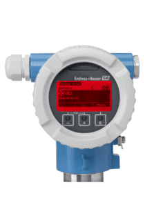
FIGURE 3. Pressure instrument with local display showing error code and explanation
Using NAMUR NE107 diagnostic protocols, it is possible to eliminate many of these traditional and time-consuming steps in the troubleshooting process. An instrument’s local display can provide a simple description of the issue in addition to a unique error code.
Some instruments go one step further, providing local displays with optical pushbuttons so technicians can dig deeper (Figure 3). As opposed to a physical/mechanical pushbutton, an optical pushbutton responds to covering/uncovering an optical sensor. This means it can work through glass, allowing operators to initiate changes without opening a housing and getting a hot work permit. Another feature available on some instruments is a backlight with variable colors, which can be used to provide fast and clear identification of status. The instrument can also indicate the corrective action needed to resolve the issue.
If the instrument is a model without optical pushbuttons and similar information is required, the same functionality can be accessed remotely from up to 82 ft (25 m), with the exact range dependent on environmental conditions, through Bluetooth communication to a handheld device. Using these types of features, a technician can quickly identify the problem, determine the severity of the issue, and ascertain what correct action is needed.
Enhanced safety
The importance of a safety instrumented system (SIS) continues to grow because these systems help ensure the safety of personnel, property, and processes through risk mitigation. Central to these systems are safety loops with safety integrity level (SIL)-rated instrumentation. Safety faults fall into one of two categories: random and systematic failures.
Random failures are device-related, for example a hardware failure when a resistor shorts out. These types of failures are not predictable and cannot be prevented. Device manufacturers mitigate the risk of random failures through improved diagnostics and reduced dangerous undetected failures.
Systematic failures are application- or process-based, for example improper materials of construction or faulty installation procedures for an instrument (Figure 4). These occur in a predictable manner and can be reduced through improvements in design, procedures and documentation. The net result is that risk mitigation is achievable, but 100% functional safety is not.
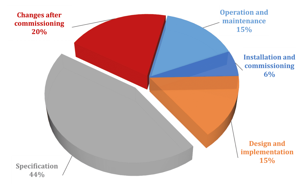
FIGURE 4. The causes for systemic failures are shown in this chart. Systematic failures can be reduced significantly through improved design, installation, operation and maintenance
The common assumption has been that 35% of failures in an SIS originate from actual operation (random) and 65% originate before operation (systematic), and a recent study by NAMUR.smart supports this assumption. Over a two-year period, NAMUR.smart worked with 33 European chemical companies to collect fault data. This study involved 85,000 SIS installations and encompassed 300,000 instruments, actuators and logic units. Less than 0.2% of these devices experienced a dangerous failure during this time frame.
Roughly 53% of the dangerous failures that did occur involved instruments, with about 30% of these dangerous failures random and therefore not preventable, and 70% categorized as systematic, and therefore able to be reduced. This is very similar to the generally accepted ratio of random to systematic failures.
Reducing systematic failures
Pressure instruments are the most widely used of all types of measurement devices in a typical SIS, and it is possible to use newer models to help reduce systematic failures and mitigate overall risk. Commissioning is the most instrument-relevant systematic failure, and instruments used in an SIS must be commissioned using specific SIL Relevant Parameters (SRPs). If the correct SRP is not utilized, a systematic failure becomes much more likely.
Traditionally, a technician is provided with a checklist specific to the instrument to be commissioned, which identifies the correct SRPs to be entered into the instrument. Once completed, the instrument is SIL-locked, and the checklist is signed and dated. But how confident is the safety engineer that the correct values were used?
- Did the technician inadvertently skip a parameter?
- Did the technician confirm a changed setting properly?
- How can the instrument help ensure the parameters are correct?
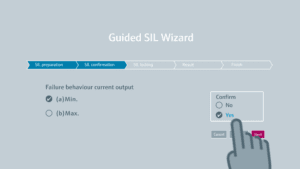
FIGURE 5. An SIL wizard guide a technician through commissioning
Basic commissioning of a pressure instrument for SIL service follows the same steps as a non-SIL device. However, pressure instruments with a SIL confirmation and locking wizard require an extra step before the unit can be placed in a SIL-lock mode. A SIL wizard leads the technician through a mandated confirmation of the SRP settings. During this process, the SRPs are in a read-only mode, so there is no risk of accidental changes. Each setting is displayed, and the technician must actively confirm the setting is correct (Figure 5).
After a SIL wizard is used for commissioning, a technician can save a signed and time stamped SIL commissioning report in PDF format on a laptop, tablet, or smartphone connected to the instrument via Bluetooth.
Final thoughts
Smart instruments have evolved well beyond just providing an accurate and reliable reading of the process variable. They can be used to help personnel in process plants and facilities by simplifying everyday activities, increasing productivity and improving overall safety through diagnostics that help users understand root causes of problems.
All figures courtesy of Endress+Hauser

Keith Riley, E+H
Author
Keith Riley is the national product manager for Pressure and Temperature at Endress+Hauser (2350 Endress Place, Greenwood, IN 46143; Phone: 317-535-2169; Email: [email protected]). He has been with the company since April 2008. Prior to this, he was a product manager and regional sales manager with L.J. Star Incorporated, as well as a Product Manager for Penberthy (Tyco Valves). Overall, he has over 20 years of sales, marketing, and instrumentation experience in the process industries.