Understand and follow these tips to ensure accurate and reliable temperature values
Even though electrical thermometers are used quite frequently in chemical process industries (CPI) plants, people often underestimate just how wrong the temperature displayed can be if these measurements are not planned carefully enough and new developments are not taken into account when selecting the right equipment. With some simple rules presented here, the accuracy of temperature measurement can be significantly improved without dramatically increasing the investment and maintenance costs.
Thermometers for the CPI
The task of a typical thermometer is to determine the temperature of the medium within a vessel or a tube and to convey this measured value to the outside. As robust designs must be selected in process technology, a modular design (Figure 1) has become established that also takes into account the requirements of maintenance staff.
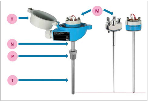
FIGURE 1. The major components of a typical electrical thermometer for process engineering is shown here (M = measuring insert; H = connection head; N = extension tube; P = process connection; T = thermowell)
The core of the thermometer is the measuring insert (M) — a standardized cylindrical component, the “hot” end of which has a temperature-sensitive sensor in it. On the “cold” side, the electrical wires are fed out of the tube or the mineral-insulated cable so that either a terminal block can be mounted or a temperature transmitter can be installed directly. The connection head (H) shields the electronics and the electrical connections against environmental influences. The extension tube (N) is used to ensure that the components within the connection head are far enough away from the process connection that they are generally protected from high or low temperatures during the process. The process connection (P) establishes the connection to the process. This generally includes threads, flanges or direct-welding connections. The area below the process connection is known as the thermowell or protective tube. This must be able to withstand the loads incurred with the process, that is, pressure, flow, chemical attack and, of course, the temperature of the medium. Thanks to this modular design, it remains possible to install or remove the measuring insert for calibration without having to open the process; that means medium cannot escape and nothing can enter the process from the outside (such as air or germs).
Energy flow in the thermometer
An industrial process thermometer made from stainless steel also establishes a metallic energy connection between the temperature of the media and the ambient temperature. As with an electrical circuit, energy flows via the heat conductor if there is a difference in temperature. The voltage decreases across a resistance and the temperature changes along the thermometer. This also leads to a temperature gradient between the inside and the outside within the thermometer structure itself. In an simplified representation, this temperature curve can be presented by a series of straight lines. Its gradient in relation to the position in the thermometer depends on the thermal conductivity of the material mix and on the ability to conduct heat via convection to the environment. Large flanges or screw connections therefore lead to a steeper profile since more energy flows out.
However, when assessing the measuring accuracy, it is the temperature curve within the process that is particularly relevant, that is, the area where the thermowell is immersed in the medium. Figure 2 shows that the temperature in the thermometer increases from the starting level at the process connection towards the tip of the thermowell.
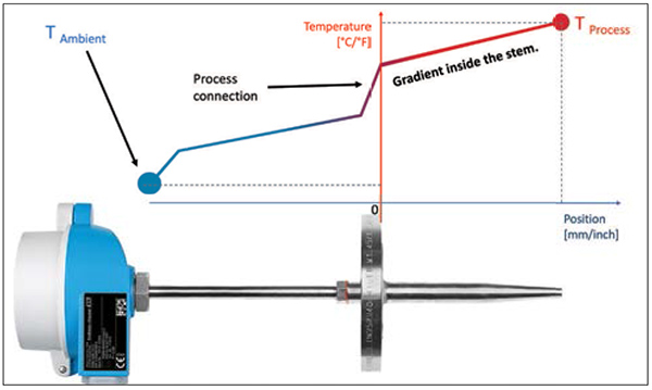
FIGURE 2. Shown here is a simplified temperature gradient along the length of the device for the case when the process temperature is greater than ambient
(Note: The example in this article describes the case in which the process medium is hotter than the ambient temperature, that is, heat energy is withdrawn from the process and transferred to the environment. In the case of cold media, energy flows from the outside into the process. All the rules apply here as well, but with the signs inverted: all installation-related errors in cryogenic applications are “positive” instead.)
The most important rule for any contact thermometer, however, is the following: Every contact thermometer can only show the temperature that its physical sensor itself experiences.
For any further analysis, it is important to consider where in the thermometer this sensor, such as a Pt100 measuring resistor, is actually installed, but also the size of this sensor is relevant because the temperature along its position may not be constant.
Figure 3 therefore shows the cross sections of various measuring inserts on which the surrounding powder or casting material has been removed. The designs vary depending on the choice of sensor and its position inside the measuring insert.
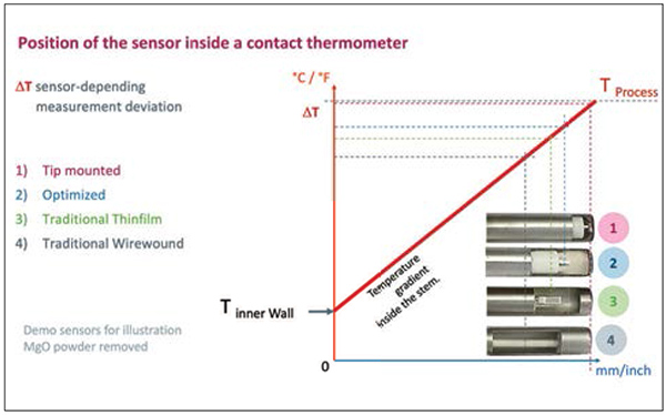
FIGURE 3. The temperature gradient inside the stem of the device is influenced by the size and location of the sensor
Sensor position
If we graphically transfer the distance from the tip to the expected temperature gradients, a direct qualitative connection can be read off between the installation position and the measurement result. The further the measuring position is away from the tip, the larger the deviation from the actual process temperature. In the application shown in Figure 2 — a process that is hotter than the environment — this installation error is always negative, that is, the process is in reality hotter than the value displayed.
With a traditional design with a wirewound resistor (No. 4 in Figure 3), a temperature-sensitive area is created, which starts approximately 5 mm from the inner wall of the measuring insert and ends at approximately 20 mm. The display therefore shows the average temperature in this area. According to the simple model in Figures 1 and 2, this therefore corresponds to the temperature at approximately 12 mm from the tip.
A thin-film measuring resistor is much smaller, whereby the averaging effect only relates to a smaller area. In its traditional design (No. 3 in Figure 3), a sensitive area is created at a distance of between 7 and 10 mm.
In an optimized design, which can also be used if there are very high vibrations, a special manufacturing process is used to encapsulate the sensor in a type of concrete nearer to the tip (No. 2 in Figure 3). The area to be measured is therefore around 5 to 6 mm in front of the tip.
With a tip-sensitive measuring insert (No. 1 in Figure 3), it is possible to secure the sensor directly to the metal inner wall of the measuring insert. Furthermore, the Pt100 has been rotated by an angle of 90 deg so that it lies flat on the tip. In fact, the temperature-sensitive area is only approximately 1 mm away from the outer side of the measuring insert.
A very small, almost negligible error only arises if using the tip-sensitive measuring insert. However, this can only be used at temperatures up to 200°C. Since the error to be expected becomes greater when the temperature difference between the inside and outside increases, it is important to ensure the correct installation of the thermometer, especially at high temperatures.
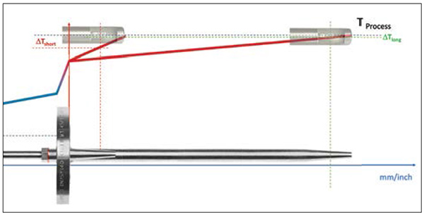
FIGURE 4. The length of the thermometer installation can have a big influence on the measured temperature value
Notes on installation
The temperature of the process connection depends in particular on how much energy is emitted from its outer side to the environment. The result is a specific temperature level that effectively represents a starting point for the residual gradients up to the process temperature. By extending the thermometer installation depth, the temperature gradient in the thermometer therefore levels off. At the position where the sensor has been installed, it is warmer with a flat gradient, which means that the accuracy of the measurement increases with the installation length.
If the thermometer is installed perpendicular to the tube, the opposite tube wall is the limit for the installation length. The solution is to install it at a flatter angle or to install it in a tube elbow, as shown in Figure 5, whereby the counterflow direction should be the preferred choice.
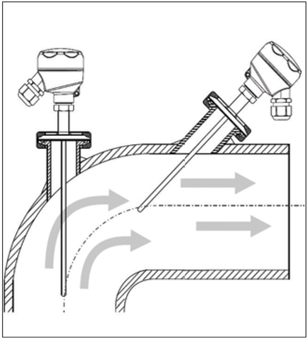
FIGURE 5. For small-diameter pipes, it is recommended to install the thermometer in an elbow against the direction of flow, to avoid potential problems from vibrations
However, a limiting factor for the length of the protective tube is its increasing tendency to vibrate the longer it is. Due to the longer lever and lower resonance frequency of the design, there is an increased risk that the thermometer will be bent by the flow, or will be made to vibrate so strongly that it can break due to fatigue. The maximum permissible length should therefore be determined by a protective tube calculation, in accordance with ASME or DIN guidelines [1, 2].
External insulation
Adding external insulation to the extension tube has a similar effect as extending the installation length, but it can also be applied retrospectively.
Thermal insulation on the outer surfaces of the thermometer increases the temperature level of these areas (Figure 6). Starting from the hotter process connection, the residual temperature gradient between the inside of the process connection and the thermowell tip is flatter than would be the case without thermal insulation. This also increases the temperature at the position of the sensor (that is displayed). Insulation on the outside thus not only improves the energy efficiency of the process, it also improves the accuracy of the temperature-measurement equipment on the inside.
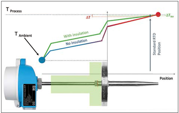
FIGURE 6. External insulation not only improves the energy efficiency of the process, but also improves the accuracy of the temperature measurement equipment
Quantifying heat-transfer errors
The size of the error caused by incorrect installation depends in particular on the temperature difference between the process and the environment. It may be up to –5% of this difference.
This means that these installation errors may have a much greater influence on the overall accuracy than either the class accuracy of the measuring insert or the measurement uncertainty of the temperature transmitter. In any further measurement-uncertainty calculation, it must be taken into account, that the error cannot be positive since the sensor cannot be at a higher energy level than the process itself. Figure 7 shows an example of a non-symmetrical distribution function.
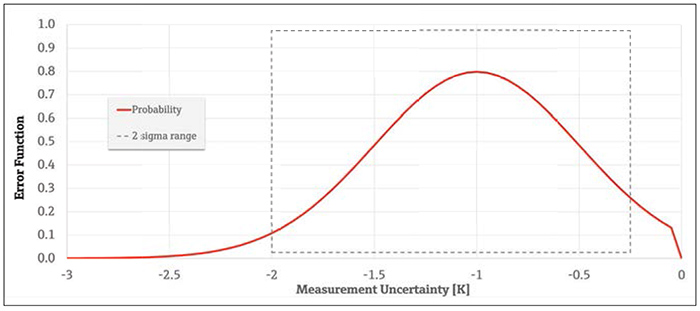
FIGURE 7. This unsymmetrical distribution shows the typical measurement uncertainty distribution of installation errors (μ = –1K ; σ = 0.5K)
Impact on closed loops
The majority of all temperature measuring points are embedded in loop systems (Figure 8).
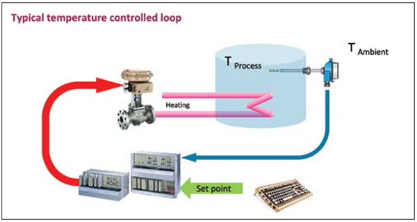
FIGURE 8. Most temperature-measuring points are embedded in closed-loop systems, as shown here
In closed-loop systems, negative temperature-measuring errors can be dangerous. Since the controller does not know about the installation errors, it interprets the measured value as being too low. As a result, the energy supply is increased until the expected target value is displayed. At the end, the actual temperature in the process is thus higher than displayed by the amount of the measuring error. This can impact the quality of the product and the safety of the system. This error will most definitely negatively impact the energy balance of the process.
Final remarks
Thermometer installation errors at temperature-measuring points can be prevented. In hot processes, heat-transfer errors are generally negative, in cryogenic media, temperatures are displayed that are too high. Sufficiently long installation lengths should therefore be planned and calculated from a safety perspective as early as the system-planning stage. External insulation will improve measuring performance and energy efficiency. By selecting the appropriate measuring insert (sensor design) for the installation situation and temperature measuring range, in which the sensor is installed as far forward as possible, the accuracy of the measurement can also be improved retrospectively.
Edited by Gerald Ondrey
Acknowledgments
All figures are courtesy of Endress+Hauser.
References
1. DIN 43772 Supplement 2:2015-06, Control technology — Protective tubes and extension tubes for liquid-in-glass thermometers, dial thermometers, thermocouples and resistance thermometers; Supplement 2: Calculation of protective tubes, Beuth Verlag, https://dx.doi.org/10.31030/2301583.
2. The American Society of Mechanical Engineers, Thermowells — PTC 19.3 TW — 2016, www.asme.org/codes-standards/find-codes-standards/ptc-19-3-tw-thermowells.
Author
 Dietmar Saecker is senior application expert for Industrial Temperature Measurement at Endress+Hauser Temperature + System Products GmbH & Co. KG (Obere Wank 1, 87484 Nesselwang, Germany; Phone: +49-8361-308-0: Email: [email protected]). In this role, he consults worldwide with users of temperature measurement in process automation to select and design the best-fitting thermometer to increase accuracy, response time and safety. Saecker is also a lecturer for measurement technology at the Kempten University of Applied Science in, Germany, where he teaches students how to select flow-, pressure- and temperature-measurement devices for specific application. He holds a Dipl. -Ing. degree in chemical engineering from the Technical University of Dortmund, Germany.