Rethinking Reactive Metal Pipe Systems: A Revolutionary Pipe Product
FREE
REGISTERReactive metals such as titanium and zirconium are long trusted by chemical plant owners, operators, and licensors for corrosion-resistance in demanding high-pressure and high-temperature piping systems. However, these metals are costly and may have design and reliability limitations including toughness and crack growth concerns when used in solid form. Cladding titanium or zirconium alloys to the interior of carbon steel or stainless-steel pipe with very well characterized mechanical properties offers the anti-corrosion benefits of reactive metals at a significantly reduced cost.
NobelClad has developed a unique cladding process that greatly exceeds the loose-lining process, allowing for a substantially higher mechanical integrity across the entire piping system. The product is marketed as DetaPipe™ and can be formed into pipes and elbows and soon into tees, ranging from 3-inch NPS (80 DN) to 30-inch NPS (750 DN). The new pipe adheres to the ASME B31.3 standards and withstands pressure ratings from full vacuum to well above 70 bar (1000 psi). Pipe spools have several connection types such as ANSI B16.5 or ANSI B16.47 flanges, including other commercially available energized seal options.
During this presentation, the authors will present the general mechanical properties and attributes of this clad pipe product, and how it offsets the concerns of using solid refractory metals when handling acids such as acetic acid, acrylic acid, nitric acid, sulfuric acid, urea, and many more.
Offered Free by: NobelClad
A Universal Equation for Designing Pipelines
The pipe-flow equation presented here can be used to properly and easily size pipelines for liquid, vapor and two-phase flow. Example calculations are also shown
Sizing pipelines is a fundamental task for design engineers, who typically use several equations to size pipes for different flows (liquid/vapor/two-phase). The flow equations, however, are basically analogous. Incompressible flow calculations are considered relatively simple and easy to do. However, a major challenge faced by design engineers is sizing a pipe flow that experiences significant variations in the flow density and velocity.
Generally, calculations for vapor or two-phase piping often involve repetitive calculations for accurate results. Sizing a pressure-relief system that operates at very high velocity and high pressure drop is a difficult application. Vapor flow and two-phase flow in relief-discharge piping involve rapid changes in density that result in very high line velocities. The calculation methods of the American Petroleum Institute (API) have been widely used in industries for sizing relief system piping [1]. For vapor flow, the relatively conservative isothermal equation is recommended. And if the pipe system handles vapor and flashing or non-flashing liquid, the homogeneous equilibrium equation is suggested. Consequently, emergency-relief-system designers use several pipe-flow equations to size relief system pipes [1].
This article presents a universal pipe-flow equation to properly and easily size pipe lines for liquid flow, vapor flow and two-phase flow, and suggests appropriate and convenient calculation procedures. The universal equation for pipe flows is developed by modifying a universal mass-flux equation for sizing relief valves previously developed by Kim and others [2]. This article provides an overview of the pipe flow equations and highlight the key considerations. Additionally, four example calculations are provided to illustrate the application of the universal equation for pipe flows.
Review of existing equations
Those who design pipelines that are intended for fluid transportation are expected to cope with the calculation of pressure drop in a piping system. Pressure losses consist of three different components for a pipe system at a given velocity. Generally, total pressure loss in the pipe system is the sum of friction loss, acceleration loss and elevation loss, as shown in Equation (1). However, Equation (1) does not precisely represent vapor and two-phase systems that involve an additional compression term.
For the friction loss term, one of the most useful and important equations is the Darcy-Weisbach equation, Equation (2).
Equation (2) is often expressed in terms of average specific volume [3]. Therefore, the friction losses in pipelines can be computed directly using Equation (2) or Equation (3).
Although the two equations seem to be identical, they give different results when applied to vapor and two-phase flows because the average density is not the reciprocal of the average specific volume. Equation (3) has been found to generally over-predict friction losses where the change in density is significant. However, the over-prediction decreases with an increase in the number of pipe segments with Equation (3). This indicates that Equation (3) should be used on a pipe segment-by-segment basis. On the other hand, Equation (2) should be based on the entire pipeline in one calculation, rather than a pipe segment-by-segment basis in numerous calculations.
Equation (4), which accounts for the three pressure loss terms including a compressible term, is a general homogeneous equilibrium model for pipe flows [4–5]. This general equation can be derived by integrating the Bernoulli equation.
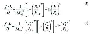
Equation (5) is an isothermal vapor-flow equation based on the inlet Mach number. On the other hand, Equation (6) is based on the outlet Mach number. The sizing of relief discharge piping at a given outlet pressure is generally performed with Equation (6), calculating back through the piping system to verify actual backpressure at each pressure relief device. For non-ideal gases, an incremental or stepwise approach is usually required to account for the changes in compressibility factor. API recommends this isothermal vapor equation that results in slightly more conservative predictions for most cases [1].
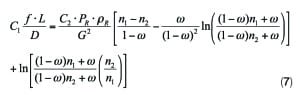
If the system handles mixed phase fluids, the sizing calculations are complex. Equation (7) is generally used to determine pressure drop in multi-phase systems for a horizontal line [1, 6]. This equation is based on the homogeneous equilibrium-flow assumption to determine line pressure losses caused by friction and acceleration terms. Performing an isenthalpic flash for the pressure ranges of interest is required. However, Equation (7) can also be used for single liquid or vapor flow.
All the existing equations above that are based on the same derivation from the Bernoulli equation are technically identical. Although Equations (4) through (7) are widely used in industry, Kim and Singh presented a new model for pipe flows to correct an inherent problem with those equations that the acceleration term was not considered appropriately [8–9]. The new model for pipe flows that corrected the acceleration term, including compression term, has improved the calculation accuracy. Using an average specific volume for the acceleration term is necessary to correct the problem identified by Kim and Singh [8–9].
A universal equation
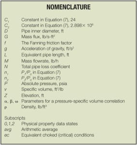
As a fluid flows through a pipe, the flow is resisted by pipe friction and the specific volume and kinetic energy increase. Several factors affect the friction loss in pipes: the density and viscosity of the fluid being handled; the size of the pipes; the roughness of the pipe internal surface; the length of the pipe; and fittings in the pipe. The friction factor of f in Equations (4) through (7) can be calculated from the Reynolds number of the flow and the relative roughness of the pipe. For simplicity, it is assumed that frictional losses in the piping system are constant to develop a pipe flow equation. This means that the total pipe frictional resistance factor of N is independent of the Reynolds number. This article does not include the details on how to calculate the friction factor, because many accurate and convenient equations are available for evaluating the friction factor. The changes in elevation within the system and the changes in the specific volume of the fluid also contribute to the total pipe frictional losses.
However, the changes in temperature are relatively small for most cases. Therefore, the pipe flow can be considered isenthalpic. By the way, either an isenthalpic flow path or an isentropic flow path can be modeled for a universal equation for pipe flows. For flashing two-phase flow, equilibrium flashing conditions are considered achieved if the pipe length is longer than the minimum required length of 4 in. for equilibrium [7]. Therefore, the homogeneous equilibrium model (HEM) based on the isenthalpic flow path is popular because this model yields a conservative design.
The universal equation for pipe flows is based on the following conservative and valid assumptions:
- The flow is steady
- The flow is one-dimensional
- The flow is in thermal equilibrium
- The flow is homogeneous
- The system is isenthalpic
- The fluid has a Newtonian flow behavior
- A pressure and specific volume correlation fits the data well
The universal equation for pipe flows, Equation (8), is developed by modifying a universal mass-flux equation for sizing relief valves [2]. However, Equation (8) is not applicable for sub-cooled flashing flow.
Where:
As shown in the equations above, average density and average specific volume determine the mass flux for a given piping system. Therefore, a pressure and specific-volume correlation, Equation (11), is a crucial component of the universal equation that enables design engineers to complete a pipe-sizing task with only a few flash calculations. Kim and others presented the details on how to determine the two parameters (alpha and beta) in Equation (11) [2].
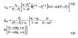
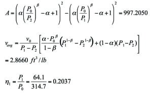
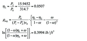
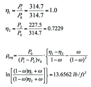
Two important values in Equation (9), average density and average specific volume, can be obtained by taking an arithmetic mean value of the densities or specific volumes over about 15 segments that are based on a constant pressure interval. However, the average specific volume and the average density can also be estimated using Equations (12) and (13), respectively. Equation (12) results in the best average specific volume. Equation (13) was derived from Equation (7) and is used to calculate accurate average density. One should be aware that Equation (13) requires an omega value or alpha value if beta is almost 1.0 (alpha = omega). The omega value should be based on the data at P0 and 50% of P0. Although Equation (13) provides very accurate results if the pressure-density correlation with omega fits well, the arithmetic mean density using Equation (11) is generally more reliable. The accuracy of the pipe flow equation is closely related to the accuracy of the specific volume prediction in a piping system. Thus, it is essential for the pipe-flow equation to have a good correlation of pressure and specific volume.
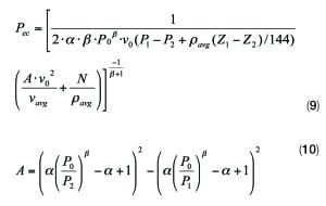
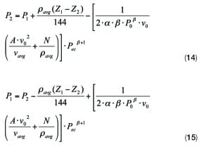
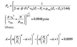
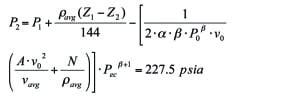
For a case of known flowrate, Equation (14) is used to predict the downstream pressure. Before solving Equation (14), one should first calculate Pec using Equation (16). The final downstream pressure is obtained by repetitive calculation when both P2 in the right side and left side are close enough. On the other hand, Equation (15) is used to predict the upstream pressure. The calculation procedures are exactly the same as for predicting the downstream pressure.
Where:
Example calculations
In order to illustrate the use of the universal equation for pipe flows, the authors considered the following four examples handling normal hexane at the reference pressure ( P0) of 314.7 psia. The piping system is at a constant pipe inside diameter of 3.068 in. (0.2557 ft). A constant Fanning friction factor of 0.00445 is assumed with a total equivalent piping of 143.6 ft. For better accuracy, one can estimate the average friction factor using one of the well-proven pipe-friction correlations that requires additional average viscosity information. One should define a simple polynomial equation where viscosity varies with pressure.
The total pipe loss coefficient, N, is calculated to be 10, as shown here:
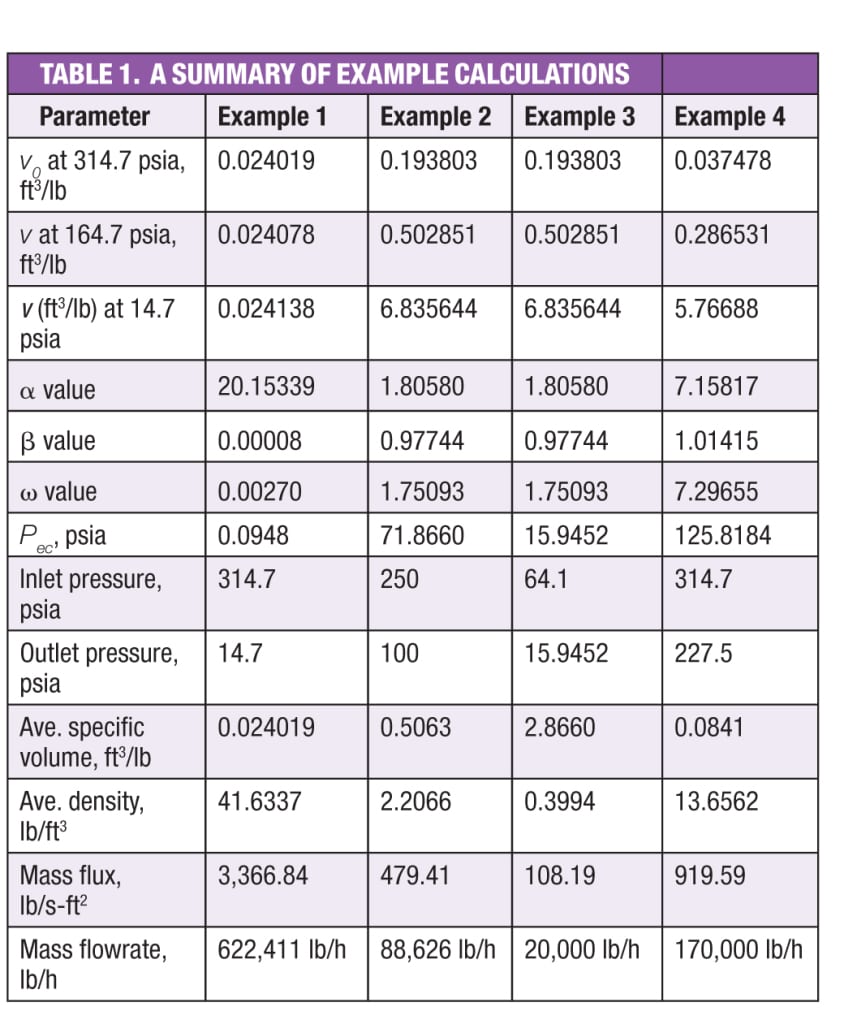
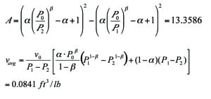
Example 1. Mass flowrate of liquid at 60°F with known upstream and downstream pressures. Calculate the mass flowrate when the pipe inlet pressure (P1) and outlet pressure (P2) are 314.7 psia and 14.7 psia, respectively. The piping system has a vertical elevation rise of 20 ft. Assume no density change for liquid flow. All input data and the results are summarized in Table 1.
First, calculate the Pec. A lower Pec value than 14.7 psia means that the system is not choked.
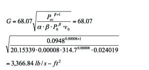
Second, calculate the G.
Third, calculate the mass flowrate.
Example 2. Mass flowrate of vapor at 314.7 psia and 413°F with known upstream and downstream pressures.Calculate the mass flowrate when the pipe inlet pressure (P1) and outlet pressure (P2) are 250 psia and 100 psia, respectively. The piping system has a vertical elevation rise of 20 ft. All input data and the results are summarized in Table 1.
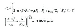
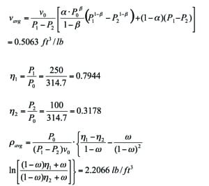
First, calculate the Pec. The Pec calculation requires average density and average specific volume. A Pec value that is lower than 100 psia means that the system is not choked.
Where:
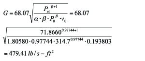
Second, calculate the G.
Third, calculate the mass flowrate.
Example 3. Inlet pipe pressure of vapor at 314.7 psia and 413°F with known downstream pressure and flowrate.Calculate the inlet pipe pressure when 20,000 lb/h vapor is flowing into a vessel operating at 14.7 psia. The piping system has no vertical piping section. All input data and the results are summarized in Table 1.
First, calculate the G.
Second, calculate the Pec. The higher Pec than the vessel operation pressure of 14.7 psia means that the flow is choked at 15.9452 psia. So, the pipe inlet pressure should be calculated with the pipe outlet pressure of 15.9452 psia.
Third, calculate the P1 with an initial P1 value (1.05 times P2). Iterate P1 calculation with the previous P1 value until there is no change in P1. The following is the final calculation after several iterations:
Where:
Example 4. Downstream pressure of saturated liquid at 314.7 psia with known upstream pressure and flowrate.Calculate the downstream pressure when the upstream pressure is 314.7 psia at a flowrate of 170,000 lb/h. The system is a horizontal piping. All input data and the results are summarized in Table 1.
First, calculate the G.
Second, calculate the Pec. If the value of Pec is greater than 314.7 psia, the pipe size is to be increased.
Third, calculate the P2 with an initial P2 value (0.95 times of P1). Iterate P2 calculation with the previous P2 value until there is no change in P2. The following is a final calculation after several iterations:
Where:
Final remarks
The universal equation for pipe flows, Equation (8), which is based on a homogenous equilibrium model and a Newtonian flow behavior, is simple and useful for designing piping systems as demonstrated in the example calculations. However, as with other general pipe-flow equations, the universal equation cannot be applied to non-equilibrium situations and sub-cooled flashing flow and special handling fluids, such as slurries and non-Newtonian fluids.
This article also examined the existing calculation procedures to develop a new procedure that is convenient and easy to follow as demonstrated in the example calculations. In those cases with significant velocity changes, it is possible that the universal equation based on isenthalpic flash may deviate from the actual flow path. It is well known that the actual pipe flow path is somewhere between isentropic and isenthalpic flow paths. Therefore, the authors are currently developing the calculation procedure for the actual flow path. In the meantime, the universal equation for pipe flows presented in this article can help design engineers complete their assigned tasks with a better understanding of the key parameters in pipe-flow equations, and even manipulate the equation for achieving successful and superior results.
Edited by Gerald Ondrey
References
1. American Petroleum Institute, Pressure-relieving and Depressuring Systems, ANSI/API Standard 521, 5th ed., January 2007.
2. Kim, J. S., Dunsheath, H. J., and Singh, N. R., “Sizing Calculations for Pressure-Relief Valves, Chem. Eng. February 2013, pp. 35–39; www.chemengonline.com/sizing-calculations-for-pressure-relief-valves.
3. Center for Chemical Process Safety (CCPS), “Guidelines for Pressure Relief and Effluent Handling Systems, AIChE, New York, N.Y., 1998.
4. Darby, R., Size Safety-Relief Valves for Any Conditions, Chem. Eng., September 2005, pp. 42–50; www.chemengonline.com/articles.php?file=2005%2FCov%2FCov09012005_01.html.
5. Simpson, L. L., Navigating the Two-Phase Maze, International Symposium on Runaway Reactions and Pressure Relief Design, A. Melhem and H. G. Fisher, eds., Design Institute for Emergency Relief Systems (DIERS), AIChE, New York, meeting held in Boston, Mass., August 1995, pp. 394–417.
6. Leung, J. C., Easily Size Relief Devices and Piping for Two-Phase Flow, Chem. Eng. Progress, December 1996, pp. 28–50; www.chemengonline.com/sizing-calculations-for-pressure-relief-valves.
7. Crowl, D. A. and Louvar, J. F., “Chemical Process Safety: Fundamentals with Applications, Prentice Hall, Englewood Cliffs, NJ (1990).
8. Kim, J. S. and Singh, N. R., A Novel Adiabatic Pipe Flow Equation for Ideal Gases, ASME Trans. J. of Fluids Engineering, January 2012.
9. Kim, J. S. and Singh, N. R., A Novel Equation for Isothermal Pipe Flow,” Chem. Eng., June 2012, pp. 66–70.
Authors
 Jung Seob Kim is a principal process engineer at SK E&C USA Inc. (1430 Enclave Parkway Suite 150, Houston, TX 77077; Phone: 281-258-2619; Email: [email protected]) where he is responsible for designing petrochemical and petroleum-refinery plants. He has more than 30 years of experience in different roles with the petrochemical process industry including with Bayer Technology Services, Samsung BP Chemicals and Samsung Engineering. He holds a B.S.Ch.E. from the University of Seoul, is a member of AIChE, and is a registered professional engineer in the state of Texas.
 Heather Jean Dunsheath is a process safety specialist at Covestro LLC (8500 West Bay Road MS 21, Baytown, TX 77523; Phone: 281-383-6879; Email: [email protected]) where she has more than nine years of experience designing emergency relief systems and facilitating process hazard analysis studies. She holds a B.S.Ch.E. from Rice University.
 Taek Kyoung Oh is a junior process engineer at SK E&C (SK G.Plant, 100 Euljiro Jugn-gu, Seoul 100-847, South Korea; Phone: +82-2-3771-5431; email: [email protected]) where he has experience with process design, process modeling, utility services and emergency relief system design. He holds a B.S.Ch.E. from Chung-Ang University.
