Wet Surface Air Coolers For Cryogenic Systems
FREE | November 16, 2022
REGISTERBy condensing at lower temperatures, the Wet Surface Air Cooler allows for increased condensing capacity when compared to dry coolers. When comparing to traditional evaporative cooling techniques, such as cooling towers and heat exchangers, the wet surface air cooler can save water as well. Traditional clean water sources are not required so alternative makeup streams allow even further savings.
Applications such as LNG, cryogenic distillation/separation and other industrial refrigeration processes can reduce operating costs and carbon footprint through the use of direct latent heat rejection via Wet Surface Air Cooling. The evaporative condensing process reduces the amount of air required for cooling and thus lowers motor power consumption as well.

Air Coolers Versus Shell-and-Tube Water Coolers
As shown here, economical cooling is often achieved with a combination of both air and water cooling. Design considerations are also presented here
For the last 40 years, air-cooled heat exchangers have become an indispensable part of many chemical, petroleum-refining, petrochemical, gas processing and power plants, as well as off-shore platforms. In locations such as the Middle East, where the availability of cooling water is limited and expensive, air-cooled exchangers may be a preferred choice. However, even there, due to various process constraints, air cooling alone may not always suffice, so water cooling may also be required.
Similarly, where cooling water is plentiful, shell-and-tube coolers may not always be a straightforward solution. Due to the need for elaborate cooling-water piping circuits, a cooling tower, large cooling-water circulation pumps and water-conditioning systems, the complexity and capital requirements are generally very high, leading to a preference for air coolers over shell-and-tube coolers. In this article, with the help of a case study, the author discusses situations where the combination of both air cooler and water coolers can be used, including considerations for better overall project economics.
Why use air coolers?
Even though overall economics play a major role, an air-cooled heat exchanger is used extensively in all kinds of on-shore plants and off-shore platforms as a first choice of cooling mechanism for one of the following reasons:
Total installed cost (TIC). The TIC of an air-cooling system is less than that of a cooling water system. Due to lower thermal conductivity and specific heat of air compared to water, the heat-transfer coefficient will be about one third that of a water-cooled exchanger, leading to higher heat-transfer area in air coolers. In addition, an air cooler requires elaborate structures, which further increases fixed costs by anywhere from three to ten times that of a shell-and-tube water cooler, depending on materials of construction. Nevertheless, an air cooler is usually preferred to avoid, completely or partially, the requirement of elaborate cooling-water piping circuits, cooling tower, cooling-water circulation pumps and water-conditioning systems and so on, because such additional equipment incurs much larger fixed costs. In addition to that, the operating cost of pumping raw water, make-up water and power for cooling-tower fans makes the TIC of water-cooling system much higher than an air-cooling system, which only requires operating costs for the fan power and some controls, such as variable frequency drive, louver and so on (see the case study, below).
Fouling. The costs associated with fouling are usually lower for air cooling compared to water cooling. Shell-and-tube coolers, the cooling-tower basin and other peripheral equipment require regular maintenance due to extensive fouling and scaling, and also biological treatment is required, without which the performance of the operating plant drops substantially due to deposition or fouling in the shell-and-tube coolers. Air coolers may also become fouled on the outside due to the accumulation of dust, insects and other debris on the finned surface, but less maintenance is required to handle this. Where shell-and-tube overhead condensers or trim condensers are used for cooling or condensing column overhead vapor, any drop in performance due to fouling can mean loss in processing material (hydrocarbon, chemical) and thermal energy. As a result, the column pressure can be affected and the hydrocarbon material is lost in slop, or flared, or the production of lower-grade material.
Flexibility. An air cooler offers more flexibility for controlling the process-fluid outlet temperature. There are various ways to safe energy by controlling the process-fluid outlet temperature in an air cooler, as follows (see also the case study below):
- Switching one fan off during winter months or during the night time
- Using variable-speed drive motors having 10–100% operable range
- Using auto variable-pitch fans where blade angles change to draw more or less air (power)
Such operational flexibility is non-existent in shell-and-tube coolers, as rarely any control is provided for the cooling water side of water coolers.
Location. No specific location is required for air coolers. However, any process plant that uses a shell-and-tube cooler together with a water-cooling system will be preferred when the location is near a source of water, such as river, lake or the sea.
Power. In the event of a power failure, cooling can continue in an air cooler by natural convection. When fan motors fail to run due to mechanical or electrical problems, an air cooler can still provide cooling of 10–15% of the design heat duty by natural convection. Loss of power or other mechanical issues in a shell-and-tube cooler can cause the water to be heated up more than the desired outlet temperature, causing scaling and fouling.
Why shell-and-tube coolers?
Cooling range. Air coolers can be used mostly as primary coolers for process fluid that requires cooling before storage. If a process fluid is to be cooled or condensed from 100°C or above, to 45°C or below, an air cooler can first cool the process fluid down to 65–70°C, then further cooling is provided by a shell-and-tube water-trim cooler for final cooling before it proceeds for rundown or storage. A shell-and-tube cooler or condenser may not be a direct choice due to the probability of high tube-skin temperature, which can lead to scaling in the tubes. Where process cooling is in a lower range (70–45°C) obviously air coolers cannot be used at all, and shell-and-tube water coolers are the only choice.
Approach temperature. Shell-and-tube water coolers can accept a lower approach temperature. For an air cooler, an economical approach temperature between the outlet of process fluid and the ambient air temperature is generally 15–25°C, whereas for shell-and-tube water coolers, the approach temperature can be as low as 5°C.
Winterization. In cold climates, air coolers require extensive winterization arrangements to protect against congealing (due to low pour point of process fluid) or freezing for very low air-inlet design temperature. Elaborate ducting with louvers, actuators, steam coil or heating fans under each fan can increase the capital cost many times. In shell-and-tube water coolers, simply switching the cooling medium to a tempered water system can prevent freezing of the process fluid.
Plot areas. Air coolers require a large plot area due to the larger heat-transfer area requirement. In contrast, a shell-and-tube cooler is very compact and requires much less space.
Location and performance. The performance of air coolers is affected by the proximity of other structures. The efficiency of air coolers goes down drastically when the wind direction changes seasonally, affecting air inlet temperature to the bundles due to the presence of furnace stack, columns and other equipment in the path of the changing air-flow direction. Because these equipment cannot be positioned very far from other structures due to space constraints in the operating plant, the air temperature may increase by few degrees. Also, if sufficient space is not allocated between air coolers and columns, furnaces and buildings in the same unit, hot-air dispersion gets hampered, leading to hot-air recirculating to the fresh intake air. This lowers the mean temperature difference (MTD), and the area for cooling becomes inadequate.
Maintenance. Air coolers generally have higher maintenance requirements than shell-and-tube condensers. An air cooler consists of many static and rotating components that may have maintenance issues, such as: 1) fan-shaft misalignment, leading to high fan/motor vibration which stops fan; 2) high fan/motor bearing temperature, resulting in failure of coupling and belt; 3) dust/debris/pollen built up on tubes, leading to increased air pressure drop in the bundle and reduction of airflow (some reverse flow also can be seen) leading to loss in cooling capacity; 4) corrosion of finned tubes due to salty atmosphere or mishandling by water washing and so on; 5) breakage or stuck louver or the failure of the louver positioner, causing restriction in air flow and reduction of cooling capacity; and 6) mal-operation of auto-variable pitch fan blades, as they can get stuck and then air flow cannot be adjusted by variable-blade pitch angle.
Case study
As an example, we discuss the challenges in handling a high-viscosity, high-fouling and low-pour-point hydrocarbon in an air cooler.
A residue-upgrading project in a petroleum refinery has a backwash oil cooler where hydrocarbon is cooled from 204 to 70°C. The oil viscosity is in the range of 1.4 to 40 cP and the pour point is 38°C. In this project, the engineer has restricted the Reynolds number to a minimum of 2,000. The design ambient-air temperature is 47°C. The location of the refinery does not require extensive winterization for such a liquid.
The design target for handling high-viscosity, high-fouling and congealing (low pour point) hydrocarbon is to achieve a tube skin temperature of at least 15°C above pour point, maximizing the tube velocity and the heat-transfer coefficient such that the Reynolds number lies in the turbulent region.
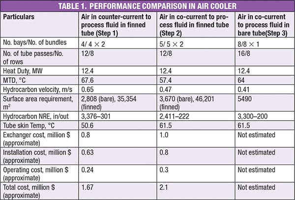
To get a reasonably high velocity in the tube side for such fluid requires increasing the number of tube passes in a deep bundle of 8 to 12 rows. But this also leads to a higher tube-side pressure drop, which can be justified economically because the increase in the operating and capital cost of the pump is small compared to surface area and cost of air cooler saved. In general, this design has a relatively higher surface area requirement. Adopting a deep bundle design also helps improve the air-flow distribution in the bundle. Bundles should have no more than one row per pass, and should preferably have at least two passes per row, so that the fluid flowing in two rows due to pass distribution, is mixed in later passes after exchanging heat with air at different temperatures in different rows. This phenomenon is shown in Figure 1.
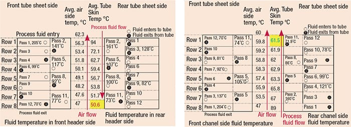
Figure 1. As seen by these two examples, the tube skin temperature in an air cooler is linked to the direction of the air flow
To avoid such a situation, and if the tube-skin temperature cannot be achieved in conventional flow arrangement (hot fluid entering from top nozzles), a co-current arrangement is tried out where process fluid enters from bottom nozzles and moves up the bundle. Due to lower MTD in such an arrangement, the required surface area goes up further. As is usually the case, this kind of design is tube-side resistance controlling, and a bare-tube design instead of finned tube will be less expensive. Even after all these alternatives are considered, if the design target is a higher tube-skin temperature and a higher tube-side velocity, the Reynolds number in the transition zone is not achieved, so other alternatives must be considered, such as cooling with tempered water.
In the actual situation, the viscosity of the process fluid increases as the temperature of the process fluid falls while progressing in the tube bundle. Also, if there is mal-distribution in the air side of the multi-pass air coolers, invariably the process fluid cools more in some of tubes than in others. This will further increase the viscosity in the cooler tubes and therefore reduce flow through the tubes, which causes further cooling and more flow reduction. This process continues until ultimately, we may notice that fluid has stopped flowing in many of the tubes, and is only flowing in a very few tubes with higher velocity and turbulent flow regime. Pressure drop may be substantially higher and, unless the pump can deliver the needed head, flow may stop and fluid starts congealing.
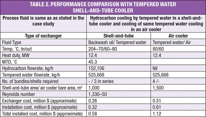
The following five design steps were considered for using an air cooler (Steps 1–3), using a tempered water shell-and-tube cooler (Step 4) and a combination of the two (Step 5). The results of the performance characteristics are summarized in Tables 1–3. Several key observations are pointed out in the following paragraphs:
Step 1. The first attempt in thermal design, using a conventional counter-current flow arrangement in an air cooler, results in a Reynolds number at the outlet of 300 (deep laminar flow) and a tube-skin temperature of 50.6°C. The design also has a high tube-side pressure drop and a low tube-side velocity, in spite of 12 tube passes in an eight-tube row bundle, and therefore high surface area requirement (high cost).
Step 2. By arranging the process fluid flow co-currently to air flow, the MTD goes down from 67°C (counter-current) to 57°C and therefore, the surface area requirement goes up. The existing design of four bays becomes inadequate in surface area, so one more bay is added (5 total). As the number of bays is increased, the tube-side velocity goes down further (0.47 m/s) and so does the overall heat-transfer coefficient, as tube side resistance is controlling by 85%. Even if the tube-skin temperature is improved, there is not much improvement in the Reynolds number, and because it is outside the user’s requirement, this method is also not adequate.
Step 3. From the above, since tube-side film coefficients are very low and become controlling, there is generally no advantage in using fins on the air side to increase the overall heat-transfer rate. Bare tube bundles with a large number of rows and split passes are more practical, as shown above. The bare surface area calculated by the software is not very high, and the power requirement is also similar to the first two designs. The real advantage of using bare tube bundles is that the number of bundles is reduced from 10 to 8, while maintaining a skin temperature of 61.5°C.
Step 4. Most of the challenges seen in the designs of Steps 1–3 can be avoided if we bring tempered water as a coolant, since normal cooling water is not suitable for cooling a process fluid with high viscosity, low pour point and a limited tube-skin temperature. When the total heat duty is cooled in a shell-and-tube, tempered water cooler, the capital cost is very attractive, as shown in Table 2. However, because an air cooler is required for cooling tempered water, the costs balance out. If a tempered water system is used elsewhere in the plant that can be tweaked and ramped up to accommodate this cooler, the scheme can definitely be made attractive. However, in spite of more turbulence due to baffling in the shell side, the Reynolds number is poor, because the bulk temperature of the process fluid is 61°C in the coldest shell.
Step 5. We can split the total cooling load into two stages and use an air cooler in a series with a tempered water trim cooler. The outlet temperature (110°C) from the air cooler is high enough to have a Reynolds number above 2,000. The rest of the heat duty can be cooled in a closed-loop tempered water system, as shown in Table 3.
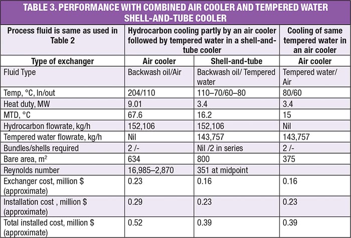
By opting for a combined system, the surface area is optimized substantially and the total installed cost is lower. An air cooler can handle a higher inlet temperature, and a high Reynolds number can be maintained by limiting the outlet temperature of the air cooler. Then hydrocarbon is passed through the shell side of a downstream tempered water shell-and-tube cooler where higher viscosity can be tackled better by considering rotated-square (45 deg) tube arrangement. As the bulk temperature in the shell is above 65°C, despite the low Reynolds number, heat transfer coefficient and shell side velocity are acceptable.
Therefore, we see that a combination of both shell-and-tube and air cooler play a definite role in the overall cost economics, and together they achieve more benefits when combined than when used separately.
Handling lube oil in air coolers
In off-shore platforms where space is at a premium, air coolers are used for cooling lubricant oil. Lube oil is both viscous and clean, and therefore it is possible to use turbulence promoters (Figure 2) or tube inserts (turbulators) in this type of air cooler. Such inserts can increase the tube-side heat-transfer coefficient by 100–250% over bare tube exchangers, with an increase in pressure drop, but without much increase in velocity. Twisted tape turbulators are formed into a helical fashion and they increase heat-transfer efficiency by breaking up the laminar flow pattern of fluids inside the tubes. The swirling fluid promotes greater contact with the tube wall (increasing shear stress at the walls many times more) enhancing tube-side convective heat transfer efficiency. The increase in values of Nusselt number, Reynolds number, Prandtl number, pressure drop and friction factor will depend upon the configuration of twisted tape (twisted ratio, pitch ratio, tape width, wire diameter and so on).
Figure 2. For applications where the fluid is both viscous and clean, twisted tape turbulators can be inserted into the tubes to increase heat transfer
Structural considerations
Support options. For an air-cooled exchanger, there are two support options: 1) to place it on pipe rack or 2) to place it on a separate structure supported from the ground. Even though air-cooled exchangers require more space than water-cooled exchangers, the majority of space problems can be resolved if they are placed on a pipe rack (Figure 3). Normally the tube bundle length is fixed, based on the width of the pipe rack. If the pipe rack width is 9 m, the tube length could be 9.5 to 9.7 m. The supporting legs of the air-cooler bundle are fixed on the main civil or structural beams, which simplifies the pipe rack design. At the same time, it is desirable to adjust the pipe rack or the structure longitudinal column spacing, based on the width of the air-cooler bundle, so that the bundle legs sit straight on top of the columns. Sometimes, it may not be possible to adjust spacing, since each tube bundle might have different widths, depending on service condition. Therefore, adjusting the pipe rack columns for different widths may not be feasible from a structural design and detailing point of view.
Figure 3. Shown here is a computer model of an air cooler mounted on the pipe rack
Walkways. There will be walkways between sets of air coolers across the length and near the headers for facilitating operators to inspect the bundle or operate the valves. The width of these walkways is generally 1.5–2.0 m. Air coolers must have access platforms mounted all around on the structure to provide maintenance. Air coolers have motors hanging at the bottom of the air-cooler plenum. Hence, it is required to have access platforms underneath the cooler for maintenance of the motors. A regular staircase should be provided for accessing the air cooler platforms or motor maintenance platforms. Monkey ladders are also provided in addition to a staircase from the structure.
Piping considerations. For a minimum of two fans per bay, the height of the underside of the fan inlet bell (for forced-draft units) or of the underside of the bundle (for induced-draft units) should be at least 2 m or one fan diameter (whichever is the greater) above the ground level, elevated floor or pipe bridge. The air coolers on the pipe rack should be located in such a way that the bundles are accessible with a crane — at least from one side.
Normally, the inlet piping of an air cooler requires a symmetrical distribution for condensers. Therefore, the number of bays/bundles is based on 2 n = 2, 4, 8, 16, 32… (Figure 4). When such an exact symmetry is not possible due to some constraint, such as pressure drop or structural limitation, efforts should be made to maximize an equivalent symmetry, as shown in Figure 5, where a total of ten bays are divided into five bays both sides and vapor is distributed equally to both sides. The piping of the air cooler needs to be supported, so either the structural columns or the pipe-rack structural columns need to be extended upwards to properly support the piping. Such data have to be given at a very early stage in the project, since this needs to be considered during the design of the pipe rack.
Figure 4. Normally, the inlet piping of an air cooler requires a symmetrical distribution
Figure 5. When a perfectly symmetrical distribution is not possible (as in Figure 4), an equivalent distribution of headers can be designed
The air coolers for an overhead system are normally used when a large quantity of vapor is required for condensation or a huge quantity of gas or liquid needs to be cooled. The major points that need to be taken care of when routing the inlet and outlet pipes are as follows:
- If the supply line has a very low operating pressure, which is usually the case for connecting a distillation column, care needs to be taken to keep the number of bends or elbows leading to the air cooler at a minimum. But functionality and stress requirements have to be considered. The length of all branch pipes for all tube bundles from its header has to be more or less similar to keep the pressure drop the same; this will ensure equal distribution of fluids to all bundles.
- Normally, the inlet-side header box is considered as fixed for the piping connection and the other header is floating. But the bundle can move in transverse direction of tubes by a few millimeters (say, 6 mm minimum) or if it is fixed at one edge, then it can move by a higher margin (say, 12.7 mm minimum) in the other direction, as per American Petroleum Institute (API, 7th edition) recommendations. Usually, this value can be anywhere between 5 and 60 mm. This header displacement is necessary to compensate for piping inlet/outlet header expansion. The value decided upon should be confirmed with the vendor of the air cooler, since the vendor may use a different displacement provision. The movement of tube bundles in the transverse direction could occur only when the piping connected to equipment nozzles generates enough force to overcome the friction at the bundle supports. That is why it is a common practice to provide stainless steel, polytetrafluoroethylene (PTFE) or other type of plate at the support point to ease the movement. But this must be done in consultation with the vendor.
- The loads created on the bundle nozzle — due to thermal expansion, the weights of the pipe, insulation and fluid, and the inside pressure of piping — should be less than the limits given by API. Sometimes the vendor allows a higher allowable load (normally two times the code value).
Locating shell-and-tube coolers. The standalone water condenser and shell-and-tube trim water cooler can be placed above the condenser drum on a structural platform supported from grade. Even though a shell-and-tube water cooler will require less space than an air cooler, some area allocation is needed on the ground (or on the platform for off-shore applications). The pressure of the cooling water reaching to the tube side of condensers and trim coolers (when on a platform) is very important for proper functioning of the condenser and the trim cooler. If the pressure drop in the cooling water circuit is not properly calculated while designing the inlet/outlet piping, the actual cooling water flowrate will be lower than that of the design calculation, and the performance may suffer as a result.
Flexibility. The operating costs for the air cooler include the electrical power required to operate the fans and sometimes power is required for heating coils in cold climates. Normally, the design of the cooler will be such to accommodate the highest expected ambient temperature (for example, 50°C), but because of seasonal changes, such a strategy would be wasteful during the periods when the ambient temperature is lower (for example, 40°C) — which can be as much as 50% for the year. Operating power costs can therefore be much lower than the installed power costs by using two-speed motors, auto-variable pitch fans and variable frequency drive (VFD) fan-motor control to reduce the air flow. In temperate climates, as much as 50% or more of the design power may be saved over the course of a year with auto variable-pitch fans.
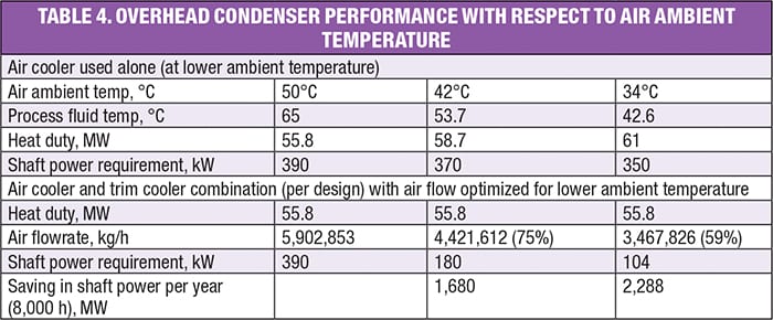
Nowadays, VFD technology has become popular and more common rather than auto variable-pitch fans, which are problematic for a number of reasons. The air requirement can be adjusted from 10 to 100% through VFD control. Table 4 presents the potential savings that can be expected by adjusting the power requirements to different ambient-air temperatures, for both a standalone air cooler, and for a combination of air cooler and trim cooler. When the ambient temperature drops to below 34°C — which can occur during 5 to 6 months over the year, the trim cooler may not even be required at all, since the total heat duty can be handled by air cooler alone. So in addition to the power savings, there will be additional savings for not using cooling water, which can cost around $0.4 million/yr. If a refinery decides to keep both air coolers and trim coolers on line, power saving through reduction of air flow via VFD is very substantial, as shown in Table 4.
Such flexibility is not possible using only shell-and-tube coolers, where operators only very rarely will adjust the cooling water flowrate by operating exchanger valves (manually or automatically). Therefore, we see that shell-and-tube and air coolers both have definite roles in the overall cost economics.
Weatherizing for colder climates. In some parts of the world, where ambient conditions are such that in winter, air temperature dips below freezing, temperature control of the process streams at the air-cooler outlet is required to prevent freezing of low pour-point hydrocarbons. This leads to a more complicated design for the air cooler, as seen in Figure 6.
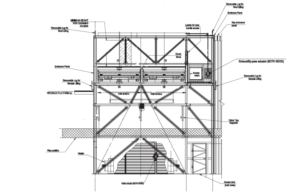
Figure 6. Shown here is a recirculation type aircooler
When a minimum tube-wall temperature has to be maintained in the air cooler, a recirculation system is employed whereby automatic louvers at the top and sides of the air cooler housing (containing the entire assembly of tube bundles, ducting, steam coils, plenums and fan motors) control the extent of recirculation. The recirculation is possible in forced-draft air coolers, since hot exhaust air can be recirculated through a duct-and-louver system.
A steam coil is generally a separate tube bundle of one or two rows having a length and width similar to the main air cooler, that is placed below the main air cooler bundle. If an electric fan heater is to be provided in place of a steam-heated bundle, the same is placed below each air cooler fan. Low-pressure (LP) steam being inside finned tubes, the steam-heated bundle and louver will involve additional pressure drop in the fan design. Closing the louver on top of a bundle allows the heating coil to warm the bundle during start up in freezing weather, so that the material in the bundle will not freeze or solidify. A steam coil is also used to temper very cold air to the bundles in continuous operation while the fan is operating and the exhaust louver is open. When two fans are operated per bay, an auto-variable-pitch fan or fan with VFD is kept at rear end of the bundle, so that the process fluid outlet temperature can be controlled.
Controlling recirculation. A part of the air leaving from the top of the system is recirculated and mixes with fresh air entering from the sides so that the combined temperature is precisely the design ambient temperature. The lower the ambient temperature, the greater will be the extent of recirculation.
For startup, when ambient temperature is lower than design ambient temperature, ambient air can be passed through a live-steam coil, located below the bundle, such that air approaching the bundle is heated up to the design temperature. The recirculation of exit air is gradually increased, which reduces the steam requirement. Eventually, the steam supply can be stopped altogether.
The air cooler is fitted with a duct leading from the top outlet to the bottom inlet. Louvers are placed in the bypass duct, at the air inlet and at the air outlet. The temperature of air just below the tube bundles will regulate the opening and closing of inlet and bypass louvers, whereas the process outlet temperature will regulate the opening and closing of the outlet louver. The duct sizing calculation and differential pressure drop across the dampers is carefully done to avoid failure of the system. The vendor’s scope of work will include the design of the louvers. In general, air-cooler tube-skin temperature is kept 15–20°C above the tube-side fluid pour-point temperature through this elaborate system.
Although the cost of such an air cooler is quite high, it is still preferred in colder climates to prevent icing or frosting. n
References
1. Giammaruti, R., Performance Improvement to Existing Air-Cooled, Heat Exchangers, Gas Machinery Research Council, Dallas, Tex., 2006.
2. Perkins, B.C., Which Cooling Medium–Water or Air, “Heat Exchanger Design Handbook,” Gulf Publishing Co., 1968.
3. Basics of Air Cooled Heat Exchangers, Amarcool Manufacturing Inc. Tulsa, Okla.
4. Williams, Jr., C.L.and Damron, R.D., Which Cools Cheaper: Water or Air,” “Heat Exchanger Design Handbook,” Gulf Publishing Co., 1968.
5. “Heat Exchanger and Cooling Tower Manual,” Chevron Corp., 1989.
6. Thomas, J.W., Air Wins, Even with Water Plentiful,” “Heat Exchanger Design Handbook,” Gulf Publishing Co., 1968.
7. Basic Considerations for Equipment and Piping Layout of Air-cooled Exchanger Piping, from www.whatispiping.com/piping-layout-air-cooled-heat-exchanger.
8. Exchanger Optimizer software (Trial version), Heat Transfer Research Institute (HTRI), Navasota, Tex., www.htri.net/exchanger-optimizer.
Author
 Manas K Mandal is a principal design engineer for Fluor Daniel India Pvt. Ltd. (6th Floor, Infinity Tower B, Cyber City, DLF City Phase II, Gurgaon 122 002, Haryana, India; Phone: +91-124-4570700; Fax: +91-124-4263269; Email: [email protected]). He has more than 34 years of experience in the field of process heat transfer, cost optimization studies, process design and operations, process revamp, project control and energy management. Prior to Fluor, he worked at Engineers India Ltd. Delhi and Hindustan Petroleum Mumbai Refinery. Mandal has presented many papers in various seminars on heat transfer, energy management and process improvement. Mandal holds a B.Tech. degree in chemical engineering from the Indian Institute of Technology, Delhi and Masters degree in financial management from Jamnalal Bajaj Institute of Management Studies, Mumbai, India.
