Intelligent selection and specification help to assure getting representative, uncontaminated samples from multiple process lines to a shared analyzer
Process engineers rely heavily on analytical instrumentation to ensure product quality. Properly designed systems help prevent contaminated fluids and gases from being delivered to consumers, or from reaching the next stage of production. Catching any problems as early as possible can yield significant savings in reduced product loss and system maintenance. Catching them efficiently lies largely in the method of delivery for the analysis sample.
Sample analysis has moved from the laboratory out into the plant, bringing new efficiencies to analytical operations. To minimize the costs of such systems, many facilities rely on a single, automated process analyzer to evaluate multiple sample streams in succession. In many cases, such systems include a stream selection assembly, which selectively directs multiple sample streams into a shared passage line that leads to the single analyzer.
Stream selection assemblies must deliver a representative, uncontaminated sample from a process line to a detector in the analyzer. The engineers who specify, select or design the systems should opt for assemblies that use minimal space in automatically selecting a given stream, maintain the sample’s integrity by avoiding cross-stream contamination, and quickly purge old sample material while moving the new stream to the analyzer.
Various stream selection assemblies based on double block-and-bleed (DBB) valve configurations are available. The most efficient of these assemblies are compact, with consistent flow characteristics, fast purge times, low valves for actuation pressures, and enhanced safety characteristics. In addition, user-friendly assemblies offer visual actuation and flow path indicators, compatibility with ANSI-ISA 76.00.02 (a standard that deals with modular component interfaces for surface-mount fluid distribution components), and easy maintenance and troubleshooting capacities. These characteristics are discussed in depth below. First, however, useful perspective can be gained from a brief look at how sample stream technology has evolved.
Sample stream technology unfolds
In the early days of analytical instrumentation design, engineers retrieved samples from process lines and brought them to the laboratory to be analyzed. Eventually, the analyzers migrated out into the plant. In the first such systems, individual process lines typically led to a single ball valve per line. All streams then shared a common passage to the collection device or analyzer (Figure 1).
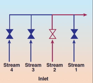
FIGURE 1. Single Block Stream Select
Method – A single ball valve blocks
sample streams leading to a common
analyzer passage. Deadlegs and valve
leakage are common.
But this configuration soon proved to have problems. As a new stream passes through the common analyzer passage, it must not only remain intact but also be free of residue from previous samples; accordingly, it must run through the system for an undesirably long period of time to purge old sample material. In addition, cross-stream contamination may occur, usually a result of internal leakage or cross-port leakage in valves. Deadlegs, or trapped volumes of sample material between the valve and common analyzer passage, also cause contamination. Deadlegs commonly arise due to the arrangement of the flow path in a device or a portion of a system.
For those reasons, sample contamination – and, therefore, incorrect analysis – was indeed common in system designs employing single ball valves. To overcome these inadequacies, system manufacturers turned to two different designs based on double block-and-bleed configurations: a traditional design and a cascading one. The main difference between the two lies in the flow path of sample material through the assembly on its way to the common analyzer passage.
In a traditional DBB system (Figure 2), each stream has two valves in a series to block sample flow to the common analyzer passage. The streams take a direct route from the process line to that passage. When the block valves are closed, a bleed valve is opened to vent the volume between the block valves to the atmosphere or to a collection device. If the first block valve leaks, the sample will flow to the vent, rather than cross-contaminate other streams in the assembly. Deadlegs, however, can still be a potential problem if users do not allow for adequate system purging.
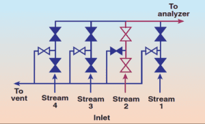
FIGURE 2. Traditional Double Block-and-Bleed Stream Select Valve Manifold – Stream 2 is shown with block valves in the open position. Stream 2 takes a direct route from the process line to the common analyzer passage. Bleed valves in Streams 1, 3 and 4 vent residual sample material.
In a cascading DBB configuration (Figure 3), one stream flows through the bottom bleed valve of an adjacent stream or streams. This approach avoids deadlegs by purging the system through the flow path. When Stream 2 is running to the analyzer, it flows through a set of block-and-bleed valves and then through the bleed valve of Stream 1 before reaching the line to the analyzer. Stream 2 thus forces out any residual sample material from Stream 1. When Stream 2 is running, its bleed valves are closed, which reduces potential sample contamination from another stream.
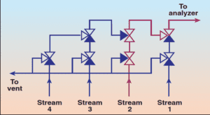
FIGURE 3. Cascading Double Block-and-Bleed Stream Select Valve Manifold – Stream 2 is shown with block valves in the open position. The sample flows through the open block valves
in Stream 2 and the open bleed valve of Stream 1. The flow path adds distance and turns that cause streams farther upstream to have lower flowrates.
Both the traditional and cascading DBB designs rely on instrument ball valves for their high flow, ease of actuation, and relative ease of use and maintenance. However, these ball valve assemblies require significant space due to the large amount of fittings, tubing, and valves needed to accomplish sample stream selection. Both of these analysis systems are, therefore, bulky and difficult to maintain.
Recent advancements
More recently, improvements in sample stream assemblies have led to modular valve assemblies that accommodate multiple process streams in a limited amount of space. Valve modules with DBB functionality control each stream, operating as both shutoff valves and stream selector valves (Figure 4).
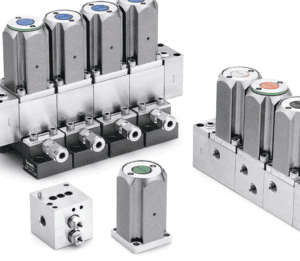
FIGURE 4. Miniature
modular stream selection
assemblies accommodate
multiple fluid streams in a limited
amount of space. The compact assemblies
also greatly reduce contamination and deadlegs.
These valves house multiple functions in one unit. End users can now have double-block, bleed, and actuation functions within a single module, rather than having to use several instrument ball valves to perform these functions. Combining the DBB functions in a compact module minimizes the total space needed to perform sample stream selection and reduces overall installation time. As system requirements change, modules can be added or removed, which also saves time.
With modular stream-selection assemblies, the engineers who design the system or who write a purchase specification for one still have a choice. In this case, there are three options: a traditional configuration, a cascading DBB configuration, and an integrated-flow-loop design.
The traditional configuration in modular form is similar to the non-modular version described above. As for the modular cascading designs, they – like their non-modular counterparts – move sample material through the bleed valves of downstream valving on the way to the analyzer passage. However, this flow path causes inconsistent flowrates from stream to stream, which is particularly a drawback in modular cascades. The primary stream – Stream 1 in Figure 3 – has direct access to the outlet. As the streams get farther away from the outlet, the flow path becomes tortuous, so the sample stream flow becomes more and more diminished. Purge times are also increased for those streams.
In the modular integrated-flow-loop design (Figure 5), by contrast, a flow loop is integrated into the base blocks of the modules, just as the name suggests. Double block-and-bleed valves open directly to the flow loop, which provides a direct route to the analyzer. Sampling and purging are streamlined. Regardless of which stream is running, the flowrates of all streams will be consistent.
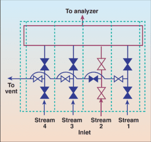
FIGURE 5. Modular Double Block-and-Bleed
Stream Select Valve Manifold with Integrated Flow Loop – Stream 2 is shown with block valves in the open position. Sample flows from the process line to an integrated flow loop. The flow loop provides a direct route to the analyzer for consistent flow
from all streams
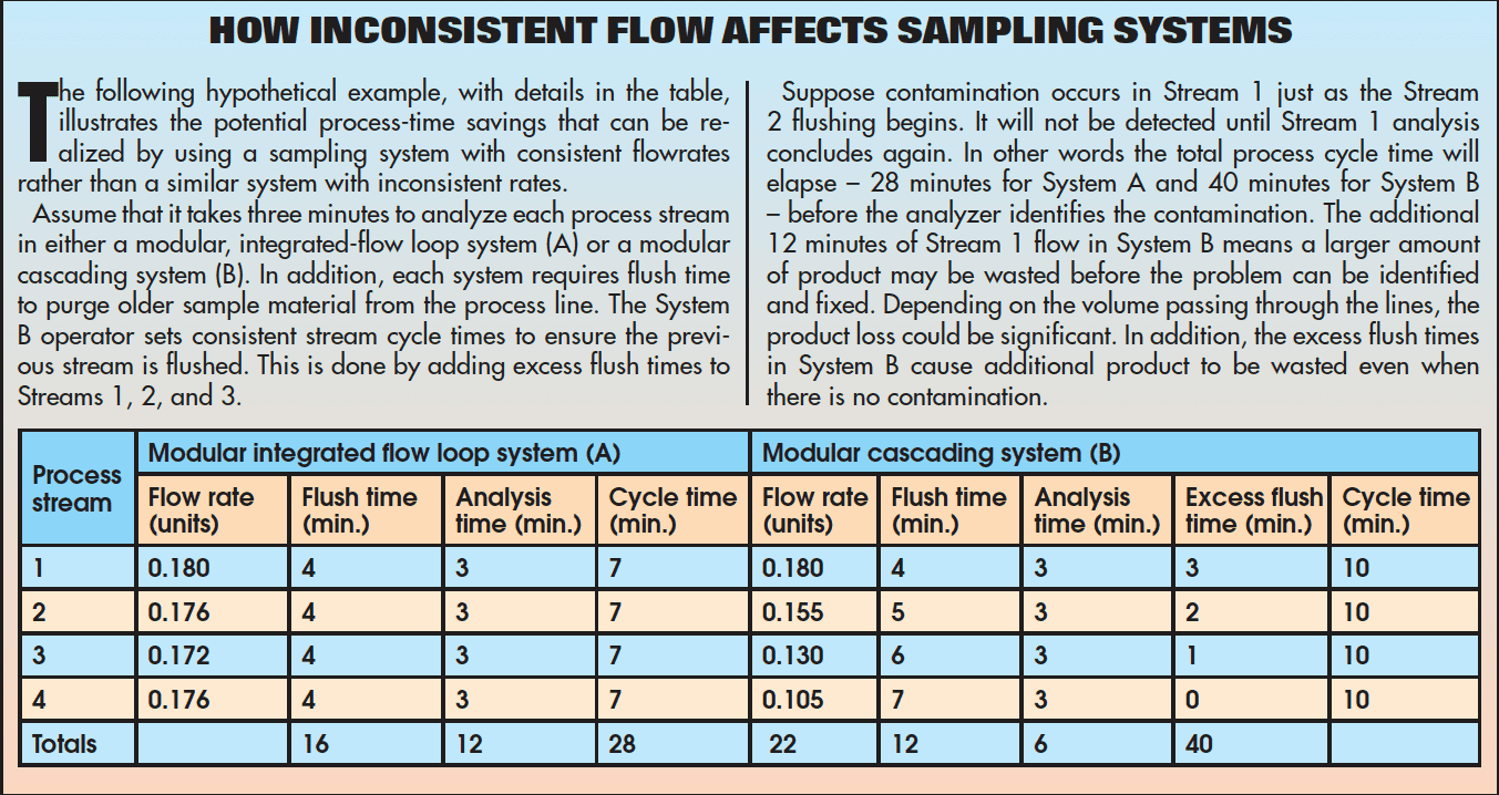
Consistent flowrates allow the system designers to set a consistent purge time and analysis time for all streams. The varying flowrates found in cascading DBB designs can lead to wasted product, as the system may be geared to purge each stream to the length of time it takes to purge the slowest stream. This practice also increases the overall analysis time, and in doing so it may also cause delays in detecting contaminated process streams (the sooner an off-specification reading is realized, the sooner the system can be shut down or corrected).
Additional considerations
Other criteria to keep in mind when choosing the best modular device for an analytical instrumentation operation relate to system compatibility, safety issues, and user-friendliness. More-specific considerations include these:
Low actuation pressures. In automated stream-selection assemblies, built-in pneumatic actuators provide repetitive shut off with fewer potential leak points than are found with conventional systems. Common industry practices dictate air-system actuation pressures of 40 psig (2.7 bar). Therefore, engineers should choose stream-selection assemblies with this rated pressure; otherwise, additional higher-pressure air lines may be needed to accommodate actuation pressure requirements that differ from the rest of the system.
Vented air gaps. Many sample-stream-selection valves are used in applications where the combination of the process fluid and oxygen under pressure can create a hazardous situation. An integral vented air gap can prevent the mixing of pneumatic-actuator supply fluid and system fluid under pressure (Figure 6). The vented air gap allows the actuator air or the fluid system medium to vent to the atmosphere or to a collection area if one or both of the seals on the valve stem on either side of the air gap should be compromised. In addition, the vented air gap keeps actuator air from reaching the analyzer.
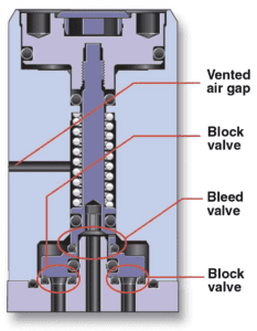
FIGURE 6. Modern valve designs feature double block-and-bleed functionality in a single unit. Some designs include an integral vented air gap to prevent the mixing of pneumatic actuator supply fluid and system fluid under pressure.
Compact size. The size of sample stream selection assemblies has been greatly reduced from the days of instrument ball valve systems. Valve designers have saved significant cabinet space by moving DBB functions into small valve modules. However, side-by-side comparisons of modular assemblies show that not all are alike. Engineers seeking to choose between systems should compare the footprint of a complete assembly for the same number of streams to determine which design best fits their size constraints.
ANSI/ISA 76.00.02 compatibility. A primary factor in the size reduction of stream selection assemblies is the advent of the aforementioned ANSI/ISA 76.00.02 specification for miniature and modular analytical systems. This specification calls for these systems to be surface-mounted onto a substrate featuring inlet and outlet connections contained within a 1.5-in.-square footprint. Stream selection valves that have been designed for compatibility with this specification save installation and maintenance time, as engineers are able to quickly mount the valves directly to substrates (Figure 7). Systems that instead require additional tubing and connections to fit into ANSI/ISA 76.00.02 substrates may increase the overall cost of the system in materials, labor, and maintenance, especially when an existing analytical system is being reconfigured.
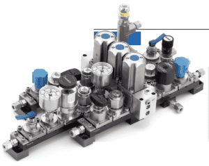
FIGURE 7. Stream selection valves can be incorporated into ANSI/ISA 76.00.02 compatible analytical instrumentation systems.
Visual actuation indicators. Operators and field engineers have found visual indicators to constitute a useful way to identify which stream selection valve is pneumatically actuated at a given time in the analytical process. These indicators provide visual confirmation of the sample system’s operation and shorten troubleshooting time. If these indicators are large and brightly colored, it becomes easier for the user to know that a given valve is open.
Stream identification. Color-coded valve caps may also be used for quick identification of the various process streams in an analytical system. For instance, a system designer could use a green cap to identify a sample stream, a blue cap to identify a zero-gas stream, and other colored caps as needed. Color-coded markings make troubleshooting and valve maintenance easier, as engineers are better able to track a process stream that is experiencing problems.
Easy maintenance. By design, modular stream-selection valve assemblies offer ease of installation and maintenance. Multiple valve modules and base blocks are connected to create the sampling system, and they are individually replaceable without removal of fluid connections. In addition, vertical disassembly of valve modules from base blocks permits easy maintenance and prevents accidental disassembly of a whole unit. Even small points in the assembly, such as independent insert bolts that are captured within the base block, contribute to a system’s ease of use.
Atmospheric reference vents. The positioning of an atmospheric reference vent between the analyzer and the stream selector system facilitates equalizing the sample loop pressure and the atmospheric pressure. Pressure equalization should usually be performed just prior to the sample injection, to ensure a constant sample pressure in repetitive analysis situations.
High-pressure valve modules. Pressure requirements in some analytical systems may fall in the 250-500-psig (17.2-34.4-bar) range. These systems will require high-pressure valve modules. The system requirements will dictate how these modules should be used within the stream-selection valve assembly.
Product cycle life. Modular stream-selection systems are actuated frequently. Therefore, when the engineer is choosing a stream select system, he or she should ask the would-be supplier to provide typical results on product cycle life or mean time to failure (MTTF) for preventative maintenance programs.
Range of materials. Analytical systems that must accommodate a wide range of process streams may require alternative seal materials. For such systems, look for assemblies that offer optional seals rated to handle more corrosive sample streams.
Summing it up
Sample stream-selection assemblies have advanced considerably, hand in hand with increased sophistication in field analytical instrumentation. These assemblies have moved from bulky, maintenance-heavy systems to miniature, modular designs that offer easy maintenance and improved performance. A variety of factors enter into the right system choice for a particular analysis process. Engineers responsible for specifying and selecting an assembly should take into account all of the particulars of the process system with which the assembly is to be used.