In continuous crystallization, it is often challenging to accurately measure mass flowrates, but the method described here enables a simpler path to a balanced crystallization process
To gain optimal value from industrial crystallization processes, it is clear that understanding specific crystal properties is essential [ 1], but it is also important to have an accurate picture of the system mass balances. In practice, accurate measurement of mass flowrates in crystallization processes can be quite burdensome, especially at large production plants, which may have less measurement instrumentation installed compared to smaller, research-focused pilot plants. This article presents a simple mass-balance model that provides a basic understanding of evaporative crystallization using six independent equations and seven unknown mass flowrates. Using this model, assessment of just one mass flowrate directly delivers the mass balance of the entire crystallization process.
Overview of crystallization
Figure 1 shows a straightforward model of a continuous crystallization process consisting of one evaporator, as in a mechanical vapor recompression (MVR) plant, or consisting of multiple evaporators in series, as in a multi-effect evaporation (MEE) plant. Corresponding process parameters and nomenclature for this example are given in Table 1. In the model, the distinction between the saturator and evaporators is purely conceptual, as in practice, both process steps are merged. The feed (F) flow is usually slightly unsaturated with respect to the solute at the conditions (such as temperature, pressure and composition) in the last evaporator. Note that feeding may take place randomly to one or more evaporators. The last evaporator is the one from which the (combined) slurry flows to the centrifuge that separates crystals from the mother liquor. In the saturator, only water (W1) is evaporated until the feed becomes saturated (SF). Therefore, no crystallization takes place in the saturator.
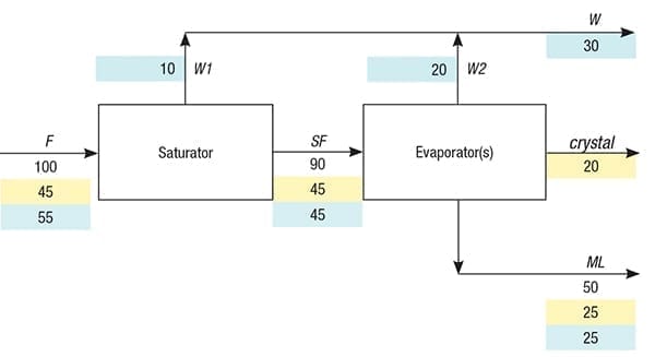
FIGURE 1. This straightforward model of a continuous crystallization process shows mass flows, with the portion of each stream representing water (highlighted blue) and process solute (highlighted yellow). The crystal mass flow indicates the part of the solute that has been turned into solid crystals
In the evaporator, water (W2) is evaporated, leading to the crystallization of solids (crystal) and concurrent formation of a saturated mother liquor (ML) flow. The total flow of water (W) is the sum of W1 and W2. The solute concentration (C, wt.%) in the feed and its solubility (S, wt.%) in the mother liquor of the last evaporator are usually easily determined analytically and considered to be known. Also considered known is the concentration factor (CF), which is the ratio of the mass flowrate of the feed and the mass flowrate of the mother liquor. In general, CF can almost always be determined via an impurity in the feed that remains dissolved in the mother liquor at crystallization, a so-called marker. Thus, CF is equal to the ratio of the marker concentration in the mother liquor and its concentration in the feed. Note that the measurement unit for the marker concentration must be mass/kg, whereas mass/L is standard for analytical data. Therefore, division by the densities of the feed and mother liquor is required unless these densities are equal. In practice, marker inclusion inside individual crystals is negligible for mass-balance purposes. The following set of equations can now be compiled where all symbols except C, S and CF reflect mass flowrates:
Overall mass balance:
F = ML + crystal+ W (1)
Concentration equation:
F = CF × ML (2)
Saturation balance:
F = SF + W1 (3)
Sub-saturation equation:
SF = C/ S × F (4)
Water balance:
W = W1 + W2 (5)
Solubility equation:
W2 = (100 – S) / S × crystal (6)
Crystallizer balance:
SF = W2 + crystal + ML (7)
Equations (1), (3), (5) and (7) are straightforward mass balances. Equations (2), (4) and (6) are concentration-based. Because Equation (7) can be derived from Equations (1), (3) and (5), this equation is not independent and can be used as a check. Mathematical stability demands that S ≠ 0.
The above equation set consists of six independent equations and seven unknown mass flowrates (F, SF, W1, W2, W, crystal and ML). Consequently, only one mass flowrate can be chosen freely and fixes the capacity of the crystallization process. This is fundamental, as after all, the above given set of equations is valid irrespective the measurement unit selected for the mass flows (meaning that ton/s is as justifiable as mg/yr).
If, for example, a feed flowrate of 100 arbitrary units (a.u.) is chosen as in Figure 1, all other mass flows are fixed, assuming that C, S and CF are known. Of course, if preferred, one of the other mass flows can be freely chosen, but then the feed flowrate is fixed.
Consequently, one needs to measure only one mass flowrate to access all other mass flowrates, which can be quite convenient, especially at large production plants. The most suitable mass flowrates to measure are either the condensate (W) or the feed (F).
Measurement of the crystal mass flow or the ML mass flow is more difficult, as at the point of separation, some mother liquor remains attached to the crystals, and tiny crystals may persist in themother liquor.
It is evident that the saturated-feed mass flowrate (SF) is technically inaccessible for measurement.
An additional feature of this approach is that measuring two mass flows (for example, W and F) provides a convenient method to check the performance of the two flowmeters involved. Furthermore, note that C can potentially be larger than S, resulting in a negative W1 value.
Natural slurry density
The natural slurry density ( NSD; wt.%) of a crystallization process is given in Equation (8) below:
NSD = 100 × crystal/ ( crystal+ ML) (8)
Substitution and rearrangement using Equations (1) through (8) shows that this NSD equation can be converted into Equation (9):
NSD = 100 × (C x CF – S) / (C✕ CF – S + 100) (9)
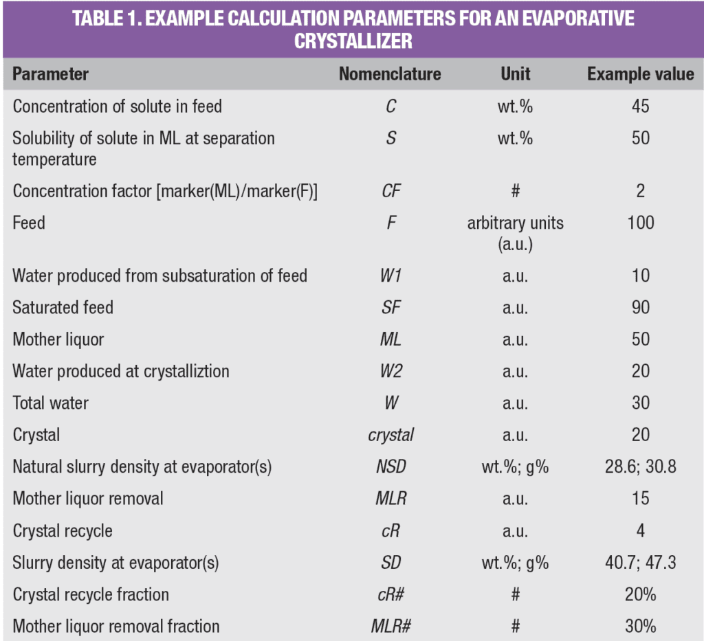
Equation (9) shows that the natural slurry density is independent of mass flowrate and can easily be calculated from C, S and CF. Also, a simple graph can be constructed that gives NSD as a function of CF, as shown in Figure 2, whereby C = S.
Figure 2. Natural slurry density is a function of concentration factor, but is independent of mass flowrate
The physical reason for the direct causality between NSD and CF is due to the evaporation of water, as illustrated in Figure 3. If water evaporates from a saturated solution, both CF and NSD increase.
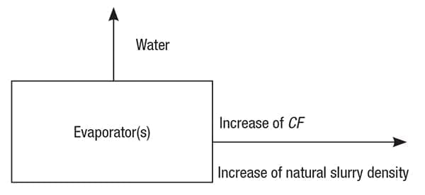
Figure 3. Water evaporation is the driving force behind the relationship
between natural slurry density and concentration factor (CF)
Glass and weight percentage
In Table 1, NSD is presented one time as a weight percentage (wt.%) and one time as a glass percentage (g%). NSD is first defined as wt.% in Equation (8), which is convenient for mass-balance calculations.
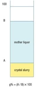
Figure 4. To determine the natural slurry density in glass percentage (g%), crystal slurry is poured into a measuring cylinder and allowed to settle freely. Once settled, the crystal slurry and mother liquor heights are used to determine the glass percentage
However, in practice, slurry density is typically determined as g%, using a glass (or plastic) measuring cylinder, as illustrated in Figure 4. To determine slurry density in g%, a crystal slurry is poured into a cylinder and subsequently allowed to settle freely, which lasts ordinarily only a few seconds. Then, g% is calculated as the height of the settled crystal slurry divided by the height of the mother liquor (both measured from the bottom of the cylinder) times 100. Equations (10) and (11) below give the conversion between g% and wt.% units.
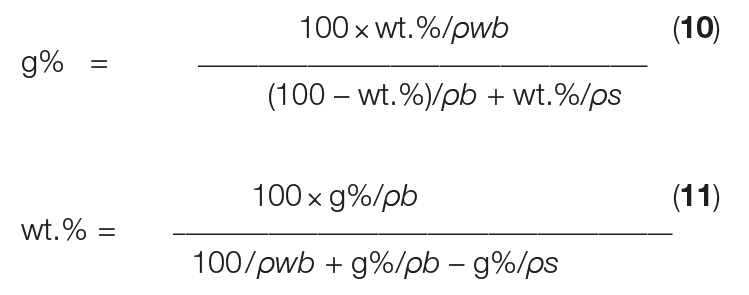
In Equations (10) and (11), ρ s is the crystal density and ρ b is the density of the mother liquor. The wet bulk density (ρwb) reflects the mass of only the crystals at 100 g% slurry density, depending on the specific shape of the crystals, among other parameters. For simple, equally sized, cubic crystals at the closest packing density, ρwb is equal to π/6 ≈ 0.5236 × ρ s [ 2].
However, in practice, determination of ρ wb is essential, because crystallization almost always results in a specific particle-size distribution (PSD) of the crystals and the closest packing is not reached. The ρwb at 100 g% actually reflects the loose bulk density — as if no mother liquor is surrounding the submerged crystals.
Changing slurry density
Usually, operational considerations (like clogging) demand that slurry density does not exceed about 30–40 g%, except for elutriation or washing legs, or exits of hydro-cyclones just upstream of centrifuges.
An excessively low slurry density may lead to fine crystals that hamper centrifuging. This shows that slurry density has a profound influence on crystallization, because slurry density determines the crystal surface available for growth (assuming constant PSD). If insufficient crystal surface area is available for growth, supersaturation increases (as evaporation is imposed on the crystallizers) until nucleation occurs.
The effect of slurry density on crystallization is temperature-dependent, because kinetics are much faster at higher temperatures. Consequently, at higher temperatures, lower slurry density can be tolerated without detrimental decrease of PSD due to excessive nucleation. Clearly, control of slurry density is essential for any crystallization process. In principle, there are two main methods to decrease slurry density:
- Crystal removal (for example, via a washing leg)
- Mother liquor recycle (for instance, mother liquor recycled from a cyclone or centrifuge)
Conversely, there are also two main methods to increase slurry density:
- Crystal recycle (for instance, a more concentrated crystal slurry recycled from a thickener or separator)
- Mother liquor removal via an annular zone
Slurry density revisited
By definition, the actual slurry density ( SD, wt.%), including mother liquor removal (or recycle) or crystal recycle (or removal) at the crystallization process is given in Equation (12):
SD= 100 × ( crystal + cR) / ( crystal + cR + ML – MLR) (12)
In this equation, both crystal recycle ( cR) and mother liquor removal ( MLR) are defined as positive mass flowrates, similar to crystal and ML in Table 1. Conversely, crystal removal is defined as negative crystal-recycle mass flowrate, whereas mother-liquor recycle is defined as negative MLR mass flowrate.
The SD equation above can mathematically be converted by substitution using the set of seven equations given before, and rearrangement, giving Equation (13):
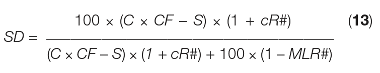
Where:
cR# = crystal recycle fraction ( cR/ crystal)
MLR# = mother-liquor removal fraction ( MLR/ ML)
This last equation shows that the actual slurry density is independent of mass flowrates and can simply be calculated from easily accessible parameters, such as C, S, CF, cR# and MLR#. Using the values given in Table 1, we see that cR# = 0.2 (logged as 20%), and MLR# = 0.3 (logged as 30%).
Crystal recycle is typically more effective compared to mother liquor removal, since the crystal/ ML ratio is most frequently less than 1. The slurry density can be increased, maintaining the same production level, because this production level is determined by the evaporation of water. The slurry density merely reflects the hold-up of crystals in the evaporator, so a slurry density increase prolongs the mean residence time of the crystals. Finally, a crystal recycle fraction larger than 1 (where crystal recycle is greater than 100%) is not an exceptional condition.
Other crystallization processes
The methodology described in this article is presented for a continuous evaporative crystallization process, but it is equally applicable for a batch evaporative crystallization process by using mass instead of mass flowrate. Furthermore, the method can be applied for cooling, anti-solvent and reaction crystallization processes. Because no solvent is removed ( W = 0) in these three crystallization methods, CF is no longer a free variable and now equals (100 – S)/(100 – C), provided that the following statements are true:
- In anti-solvent crystallization, the concentration in the feed, C, must be based on the total mass (or flowrates), so the added anti-solvent mass (or flowrates) should be included
- In reaction crystallization, the concentration in the feed, C, is the calculated concentration of the crystallizing component, based on the total mass (or flowrates) of all reactants, after complete conversion due to reaction
Now, the formulas for NSD and SD can be shortened into Equations (14) and (15), respectively:
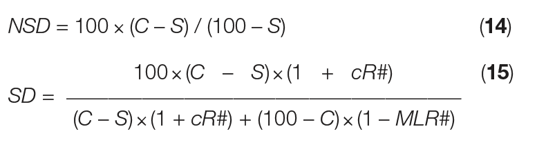
From this simple mass-balance approach, assessment of just one mass flow can unlock the mass balance for the entire crystallization process. Furthermore, this approach clarifies that natural slurry density is fixed by concentration factor, solubility in the mother liquor and solute concentration in the feed — not by mass flowrate. Similarly, slurry density is fixed by concentration factor, solubility in the mother liquor and solute concentration of the feed, plus crystal recycle and ML removal, and not by mass flowrate. Beyond evaporative crystallization, the methodology presented here is also applicable for cooling, anti-solvent and reaction crystallization processes.
Edited by Mary Page Bailey
References
1. Lewis, A.E., Seckler, M.M., Kramer, H.J.M., van Rosmalen, G.M., “Industrial Crystallization: Fundamentals and Applications,” Chapter 2, Cambridge University Press, 2015.
2. Sphere Packing, Wolfram MathWorld, https://mathworld.wolfram.com/spherepacking.html
Author
 Johannes (Jan) Albertus Maria Meijer ([email protected]l; Schalkhaar, the Netherlands) is a senior expert crystallization and chemical technologist. Now retired, he worked for 32 years at AkzoNobel Industrial Chemicals B.V., and led the salt and crystallization R&D group for the final 26 years of his career. He holds an M.Sc. with distinction in chemical technology and a Ph.D. in technical sciences, both from the Delft University of Technology. Meijer has designed 12 major crystallization processes and holds eight patents. He has authored or co-authored 27 publications related to salt technology and crystallization.