History is a constant reminder that accidents and catastrophic events can and do occur in process environments. As processes become more complex (for instance, allowing for greater operating temperatures and pressures to be used) and existing basic process control systems (BPCS) and safety systems age, risk reduction becomes more challenging. Regulations from the U.S. Occupational Safety and Health Admin. (OSHA; Washington, D.C.) and the Environmental Protection Agency (EPA) and international regulatory bodies have been put in place to help prevent and mitigate damage and injury.
Notable international standards addressing process safety include IEC 61511 and ISA 84.01. These standards cover the design and management requirements for a safety-instrumented system (SIS) from cradle to grave. An SIS contains one or more safety-instrumented functions (SIF), such as logic solvers, sensors and final control elements that act independently and separately from the basic process control system. These SIFs are selected for a given safety configuration to address site-specific hazards or events.
During system design, all constituents of the SIS must be addressed, especially the final control element, which consists of the valve and actuator, and any instrument and other accessories that can affect the valve’s movement. Data have shown that the final control element can be responsible for 50% or more of SIS failures. Any component of the final control element that can affect the safety function must be considered in the safety analysis. This includes the valve and actuator and other components (such as the positioner, solenoids and volume boosters) that can affect the valve’s ability to return to its safe state.
Since the final control element is often the weakest link of an SIS, the proper valve and actuator must be selected to improve reliability and availability and to minimize risk. In certain circumstances, the use of a control valve can provide the optimal solution to this problem. There is no specific industry requirement that defines which valve design can be used in an SIS, so control valves do not need to be limited to the realm of the BPCS. With careful consideration, a control valve can also be used as either a final control element or as a redundant element within an SIS. When designing an SIS, the use of a control valve can be considered in three potential configurations, each of which is discussed:
1. Single control valve used only for on-off safety
2. Single control valve used for both safety and control
3. Control valve used as a redundant final control element
Each configuration has its advantages and limitations, and, as with any SIS design, a thorough hazard analysis and complete knowledge of the process and its safety requirements are required to guide the selection of appropriate hardware.
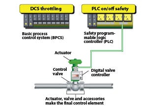
Configuration 1: Control valve used only for on-off safety. In this scenario, shown in Figure 1, a single control valve acts as the safety valve. A digital valve controller (DVC) instructs the valve to travel to its safe state upon signal from the safety logic solver (SLS), depicted as a safety PLC. This device is also capable of performing partial stroke testing and performing valve diagnostics. In fact, some digital valve controllers available can monitor the health of the external solenoid valve. A solenoid valve (not pictured) could be used as a redundant element or in place of the digital valve controller, however using a digital valve controller to perform the safety function has increased in prevalence due to its diagnostic capabilities and ability to log events and testing.
The control valve should be chosen for its suitability in the process media (considering capacity, shutoff, proper material selection and so on), and reliability. Reliability can be determined as a function of proven-in-use data (such as that compiled by the manufacturer, by a third party, or from documented user experience data), or failure-rate values (lambda), which are based on FMEDA studies, and are commonly available in third-party certificates or generically available. This failure rate information can be used to calculate the probability of failure upon demand (PFD), which can be correlated to a safety integrity level (SIL). The use of a control valve as a safety valve provides economic efficiencies, too, by increasing the number of common parts that are maintained in inventory, assuming that the SIS final control element is the same product as the one used in the BPCS.
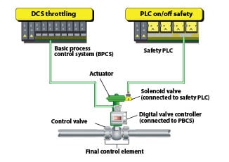
Configuration 2: Single control valve shared for safety and control. This particular application of a final control element should be considered with great care. IEC 61511 sets strict guidelines and advises that the user should, whenever possible, keep the SIS independent and separate from the BPCS. Figure 2 shows the final control element with digital valve controller that is designed as part of a BPCS throttling control. The valve also has a solenoid that the safety logic solver commands to perform its safety function upon demand.
The advantage of this configuration is that the final control element is essentially self-testing. As the valve is expected to throttle to perform its BPCS function, the end user can be confident that the valve is able to move when commanded. Another advantage is the resulting cost savings that come from having only one valve perform both BPCS and SIS functions, as well as the benefit from having common parts with other BPCS valves in the facility.
However, the limitation associated with applying a control valve in this fashion is that the valve working for the BPCS cannot cause the safety event that the valve is expected to address in the SIS. In other words, the final control element cannot be the cause of the problem it is expected to mitigate — rather, it can only be used for a safety function that is completely independent of its purpose as a control valve with the BPCS. For this reason, this type of application is technically a less-viable option, and should only be utilized with a complete and thoroughly considered up-front analysis (including process suitability, HAZOP and safety-lifecycle analysis) that ensures that this potential conflict between BPCS and SIS will not exist.
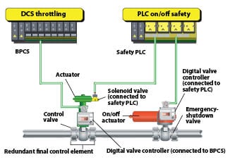
Configuration 3: Control valve used as a redundant element. A control valve can also be used as a redundant element to an emergency shutdown valve. Figure 3 shows the control valve connected in a similar way to what described in Configuration 2. The digital valve controller provides throttling control, and the solenoid valve waits for a signal from the safety logic solver to perform the final control element’s safety function.
Figure 3 also shows a second valve in series. Both valves will perform the safety function upon a safety demand, however, in the case that one experiences an issue and cannot perform the safety function, having a redundant valve improves the likelihood that the process will be shutdown safely. Two final control elements in a redundant configuration can also be solely used to perform the SIF and not be dual use (this is not pictured).
The scenario shown in Figure 3 will be a fail-closed valve. For a fail-open configuration, the redundant elements should be in parallel, both valves would be designed to be normally closed, and both final control elements would be connected to the safety logic solver ready to respond to a safety demand.
The advantage of using a control valve as a redundant safety element is that redundancy, when implemented correctly, improves diagnostic coverage and can improve the SIL rating. The primary drawback of this type of design is the cost of purchasing and maintaining multiple final control elements, as well as increased risk of spurious trips. n
Author
Afton Coleman, CFSP, is an applications engineer at Emerson Process Management, Fisher Div. (1704 Governor Rd. Marshalltown, IA 50158; Email: [email protected]; Phone: 1-641-754-3439). She has experience working with valve applications in the chemical, petrochemical, pulp-and-paper, metals-and-mining, and nuclear industries. Coleman has been supporting safety-instrumented systems in her current role since 2006. She holds a B.S.Ch.E from the University of Iowa, and has been employed with Emerson Process Management since 2005.