Safety is often underestimated when planning, operating and maintaining process-measuring equipment. Sensors with SIL certification, alone, do not make the process safe. It is important to avoid systematic errors during planning, installation and operation
The correct installation of a temperature sensor can determine whether a plant is safe for employees and the environment. Typical examples are exothermic chemical processes in which peroxides, nitrates or monomers react and control of the cooling capacity with reliable temperature measurements is vital — and sometimes control within narrow temperature limits is needed. The relationship between reaction rate and temperature follows the rule of the Dutch chemist Jacobus van ’t Hoff. According to this rule, the rate of a reaction doubles when the temperature is increased by 10K. Accelerating self-heating can therefore lead to a thermal reaction (runaway reaction).
Decisive for the measurement task here is not only the accuracy and reliability of the sensors used. Human error in the planning of the metering point, the selection and installation of the sensor and its operation can lead to systematic errors. For example, insulating adhesions on sensors can cause values to be displayed that are too low. If a temperature measuring insert is not inserted far enough into the thermowell, the measured values are usually too low. In practice, such systematic errors are the most common reason for safety problems when handling process-measuring equipment.
What applies to temperature measurement is also valid for other parameters (Figure 1), such as flow and level. Here, systematic errors can lead to tanks being overfilled or mixing ratios not being correct during production, resulting in low-quality batches.
FIGURE 1. Safe instrumentation is the result of many measures — from the planning and implementation of the measuring point to the avoidance of systematic errors during operation and instrument testing
Typical questions in flow measurement are, for example: Are the inlet and outlet distances adhered to? What must be observed after a T-pipe? Can partially filled pipes or cavitation occur after valves or with pumps? And if clamp-on devices are used, are they correctly attached/strapped to the pipeline?
Avoid selection and installation mistakes
To avoid mistakes during installation, one can refer to video instructions [1]. These short explanatory films cover the complete lifecycle: from unpacking the devices to mechanical and electrical installation to commissioning and verification.
But even before installation, there are opportunities for error: Was the right measuring device selected in the first place? Are the measuring principle, range and material suitable for the application? Are pressure shocks or corrosion to be expected? What about secondary protection in the event that medium enters the instrument housing after a defect at the process connection? And finally, the question of whether the measuring device is installed correctly must be asked.
If, for example, a temperature sensor has to be removed from the plant for calibration, this involves a comparatively large amount of work: the plant has to be shut down or at least the line in which the sensor is installed has to be bypassed. Nevertheless, the risk of leakage and contact of maintenance personnel with hazardous media remains. As support, an online webinar that points out mistakes to avoid when planning, operating and maintaining temperature sensors, is available [2].
Simple handling increases safety
An alternative to classic offsite calibration is in-situ calibration, for which special protective tubes for the sensor elements are available. These have two openings so that the calibration standard can be inserted into the same protection tube when installed. In this way, the calibration signal and temperature signal can also be compared in the installed state. This not only makes the calibration process simpler and safer, but also reduces the effort required. In practice, this leads to more frequent calibrations.
The importance of a safe measured value with regard to plant safety has already been mentioned.In order to ensure the safety of pressure measurements, elaborate 3D linearization can be used during production. With this approach, the devices for pressure and differential pressure measurement are linearized over the entire measuring range, not only for one temperature and one static pressure value, but for every theoretically conceivable constellation. This ensures that the transmitter provides the correct measured values for every possible process condition.
Systematic errors
Systematic errors can make safety integrity level (SIL) tests pointless. However, systematic errors not only affect control loops, but also occur in safety loops. Although failure probabilities are calculated for these as part of the SIL calculation and tests are carried out regularly, here, it is mostly the systematic (and usually human) errors that lead to failure.
The reason for this is illustrated by the example of an overfill protection system on a tank in which a hazardous liquid is stored. This system must be subjected to a proof test at regular intervals. How often this has to be done follows from the probability of failure on demand (PFD) calculation when designing the safety loop. PFD stands for dangerous failure probability in case of demand. How informative the test is, is in turn verified by calculation. The PTC value (proof test coverage) indicates how high the proportion of possible faults is that are detected during a proof test. If the sensor is removed and put through its paces, a PTC of 97 to 99% can usually be achieved. However, the effort required for this full test is high.
For this reason, the partial-stroke test method (partial-proof test) has been used for positioners for years. Because the test does not cover all possible errors, a PTC of 99% is not achieved, but the partial-stroke test can still be used to exclude many possible errors.
Automated testing
What applies to actuators can of course also be applied to operational measuring devices in safety functions (Figure 2). Many field devices already have extensive self-diagnostic functions and perform automatic tests — this usually allows for 95% of all possible errors to be detected. However, it gets difficult for the remaining 5%. To eliminate these in tests, the user usually has to go on site, disconnect the device from the safety loop, put it into a simulation mode and compare current signals simulated by the device with their setpoint.
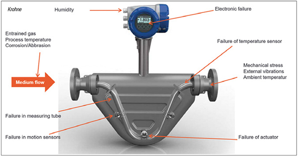
FIGURE 2. Possible sources of error in Coriolis flow measurement found via device diagnostics and partial proof tests
Time and again, devices fail to switch from simulation mode back to SIL operating mode during such tests. In addition, there are wiring errors following the test. And so the question arises as to whether the manual partial test does not actually increase the risk of failure. After all, the probability of the operator making a mistake during testing is far greater than that of a device failing due to a device error.
To avoid human errors, vendors have developed ways to automate the partial proof test. To do this, the manufacturers use a special feature of their device or the controller. For example, the SSPS HIMax can activate the HART channel, which is normally switched off in SIL mode. The safety controller then takes the field device out of SIL mode via the HART protocol and temporarily switches it to simulation mode, comparing the setpoint and actual value of the 4–20-mA signal. Finally, the device is automatically switched back to SIL mode, restarted and the HART channel is deactivated again. The results of the test are documented.
Automatic partial test
However, this is only possible with devices that allow HART commands in SIL mode. To prevent HART communication from being compromised during the automatic partial test, the SSPS saves the device configuration and detects deviations. This eliminates a major criticism of HART communication with SIL devices: in contrast to the classic setup, where the HART signal runs via a multiplexer (for example, connected to an asset management system), communication only runs between the SSPS and the field device. While hacker attacks cannot be ruled out via asset management stations, this risk is virtually eliminated with safety controllers.
Secure data transmission and storage are also important. Secure Bluetooth connections for communication with devices are now available (Figure 3).
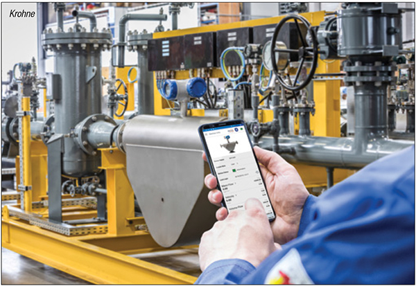
FIGURE 3. Safe measurement also includes safe communication with the measuring devices
These measures are also part of the “Secure Instrumentation” concept. In addition, for Coriolis instruments, for example, there is a housing concept that prevents medium from escaping through the transmitter housing even in the event of sensor damage.
Final remarks
Safety in the instrumentation of process plants has many facets and goes far beyond functional safety. Systematic errors represent a significant influencing variable in the planning, operation and maintenance of measuring points, and they can be avoided through training, video instructions as well as automated test procedures.
References
Author
 Lothar Gellrich is vice president Operational Marketing at Krohne Messtechnik GmbH (Ludwig-Krohne-Straße 5, 47058 Duisburg, Germany; Phone: +49-203-301-4494; Email: [email protected]). Before assuming this position in 2019, he was head of marketing communications at Krohne since 2009. Prior to this, he worked at ABB in several product-management positions. From 1996 to 2001, he was a commissioning engineer for steel-manufacturing plants at SMS Demag. Gellrich holds an engineering Diplom in electronics and automation technology from the Fachhochschule Osnabrück, and a masters degree in electronics from Middlesex University London.