When installing rupture discs, there are several mechanical and operational considerations for reducing the likelihood of leaks and fugitive emissions
Overpressure relief systems consisting of rupture discs and relief valves are vital for preventing damage and injury within chemical processing plants and petroleum refineries. These systems experience leakage or fugitive-emission problems when installed, maintained or specified improperly. Consequences for such leakage issues may include plugging, corrosion, product loss and contamination. More serious consequences may also occur, including endangering employees and the public, fines or cleanup fees issued by regulatory agencies and lost production due to unplanned shutdowns.
Rupture discs do a good job of minimizing leaks through the planned overpressure relief path. However, preventing leakage to the atmosphere between the rupture disc and holder requires proper device specification and correct installation. There is also a need for careful inspection, proper cleaning and regular maintenance of components. Understanding the various rupture disc technologies, assembly types and sealing mechanisms employed will help users prevent leakage and fugitive emissions in their plant’s overpressure relief systems.
Rupture discs under relief valves
The most common application for rupture discs is the isolation of pressure relief valves. Pressure relief valves use springs or other mechanisms to apply pressure to sealing surfaces to contain the process media. Overpressure events force the sealing surfaces to separate, releasing process fluids until the pressure drops below the set pressure. At this point, the sealing surfaces close to contain the remaining pressure. Relief valves used without rupture discs often leak, especially if operating pressures are too close to the set pressure of the relief valve. Leakage from a relief valve results in product loss, corrosion of sealing surfaces, sticking and additional wear on the valve. The added stresses on the relief valve will commonly lead to system shutdowns for maintenance at more frequent intervals. Unplanned shutdowns for maintenance prove very costly to plants and can be avoided by placing rupture discs under pressure relief valves.
Rupture discs open much faster than relief valves, create a leak-tight seal, and may be readily manufactured in a variety of materials for compatibility with most process media. They are quicker and more cost-effective to produce from expensive, corrosion-resistant alloys compared to relief valves. Once activated, the rupture disc remains open until replaced. Placing a rupture disc on the upstream side of a relief valve is an effective way for plants to utilize the advantages provided by each technology.
Rupture discs help maintain the sealing surfaces of a relief valve and keep the valve in pristine condition. In the event of an overpressure situation, the relief valve will reliably reseat itself, without risk of product buildup or corrosion. Utilizing rupture discs as a first line of defense will help extend the life of the relief valve, increase the time between required maintenance intervals and reduce overall costs related to the overpressure relief systems.
Pairing the two technologies for overpressure relief raises an additional layer of consideration to ensure the desired result is achieved. According to American Society of Mechanical Engineers (ASME; New York, N.Y.; www.asme.org) Boiler and Pressure Vessel Code (BPVC) XIII-1 UG-127(a) (3) (-b) (-4), the space between the rupture disc and the relief valve must be monitored for changes in pressure. Rupture discs are differential pressure devices, meaning that the burst pressure of the disc is dependent on the pressure both upstream and downstream of the rupture disc. If a rupture disc develops a small leak due to mishandling, corrosion or other damage, the pressure builds up between the rupture disc and the relief valve. A pressure buildup downstream of the rupture disc effectively raises the actual burst pressure of the disc. This additional pressure causes the disc to activate at a pressure higher than the intended burst pressure of the disc. As a result, it is critical to monitor this space for pressure, which is typically accomplished by using a pressure gage or a monitored pressure switch.
Rupture disc technologies
Before evaluating possible causes of leaks related to rupture discs, it is important to understand the various assembly types and the limitations of their technologies. Rupture discs are available in many different types. However, this article limits its consideration to “insert type” assemblies intended to be mounted between piping flanges. Most rupture discs can be described as one of four types: pre-bulged, composite, forward-acting scored and reverse-buckling scored. Manufacturers usually make one or more versions of each type, and may use different names or model numbers to describe them. For more information on rupture disc types and maximizing their operating performance, see Modern Rupture Discs Support Increased Capacity, Chem. Eng., June 2016, pp. 38–43.
Pre-bulged and composite types of forward-acting rupture discs were the industry standard for decades. Though they can be effective solutions for simple applications, they offer little flexibility for improving system performance. For example, neither is ideal for relief valve isolation. Both designs are susceptible to fragmentation, making them unsuitable for use under pressure relief valves. Fragmenting rupture discs can damage or get stuck in the sealing surfaces of pressure relief valves. This prevents proper closure when the overpressure event subsides. These disc types are also subject to lower operating ratios, fatigue in cyclic environments and require additional vacuum supports in the presence of negative pressures. Both designs are still manufactured today for use in angle-seat holders and more modern flat-seat holders.
Rupture disc performance was elevated with the advent of scoring technologies paired with the annealing of the metal to control the tensile strength and minimize stresses from cold-working. These processes yielded two new families of rupture discs: the forward-acting scored and the reverse-buckling scored discs. Both disc types outperform their pre-bulged and composite counterparts in terms of higher operating ratios, non-fragmenting designs and precision of activation pressures.
While users will pay higher prices for these more advanced technologies, they will benefit from increased performance and productivity through reduced downtime and the ability to operate at higher pressures. They will also find opportunities to save money by consolidating applications and reducing inventory levels. Because both scored-disc types perform well in demanding applications, replacement costs and scheduled maintenance intervals may be reduced. The consolidation of inventory paired with higher-performing discs helps users realize much larger savings throughout the plant. To reap these benefits, supervisors must provide training and continued education for all staff involved in specifying and installing these devices.
Holder sealing technologies
Angle-seat holders have long been used in the rupture disc industry. The angled surface creates a partial cone shape, which wedges together the surfaces of the inlet and the outlet. Rupture discs designed for these holders have matching angle-seat geometry. Angle-seat holders are prone to pinching through the components of the rupture disc. Application of excess torque alters the geometry of holders, deforming them to a point where they are unable to properly seal. Most rupture disc suppliers discourage the use of angle-seat holders in favor of flat-seat holders or alternative designs.
Flat-seat holders come in two main varieties, designed for either forward-acting or reverse-buckling discs. Both are designed to accommodate corresponding rupture disc designs and help to seat the disc in its proper orientation. Each manufacturer has proprietary holder designs intended to work only with its corresponding rupture disc. The seating surfaces are perpendicular to the flow path and parallel to one another (Figure 1). Each disc manufacturer also has a slightly different method for creating a concentrated force through the use of a reduced contact area. Often called a nubbin seal, this designed force creates a leak-tight seal between the inlet side of the holder and the process side of the rupture disc. This arrangement makes the rupture disc and holder much less prone to damage when torque forces exceeding the holder’s individual torque specifications are applied to the flanges. It also minimizes the damaging effects of uneven torque application. Today, nearly all high-performance scored rupture discs are mounted in flat-seat holders.
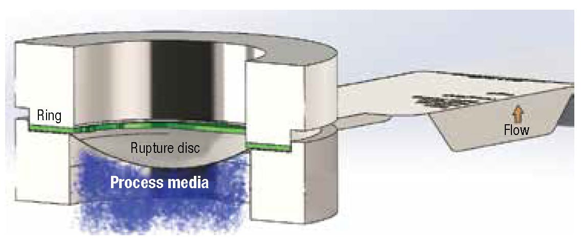
Figure 1. Holder design is important for ensuring that rupture discs are installed in the proper orientation
Pre-torque holders are flat-seat holders that allow the user to install the rupture disc into the holder and apply torque to cap screws in a controlled environment. Applying controlled amounts of torque to the preload cap screws better ensures proper disc seating before the holder is installed between the actual piping flanges. Many facilities use this type of holder so that a trained individual can clean and inspect the holder for damage that may cause leakage. The installer can then verify that the correct disc is being installed and that the disc is in its proper orientation. Proper torque is then evenly applied to the preload cap screws to ensure the disc-to-holder seal is achieved. The pre-torqued disc and holder assembly can then be passed to an individual with less training and expertise to install it into the piping system. This type of assembly may help reduce installation and leakage issues when combined with proper training and maintenance.
Usually, the technologies described previously provide satisfactory performance under the right circumstances. These assemblies must be carefully cleaned and inspected by well-trained individuals. They must then be installed in properly aligned piping precisely according to all installation procedures.
A new technology
One-piece units are the most recent evolution in rupture-disc assembly technology. They are a variation of flat-seat holders, and are beginning to emerge in chemical processing plants. These units consist of a rupture disc and holder combination that is typically assembled at the factory utilizing high-integrity welds. Companies that have experienced problems involving overpressure-relief systems understand the value derived from a sealed rupture disc and holder assembly. One-piece units eliminate installation errors due to improper torquing, mismatched discs and holders, improper disc orientation, inadequate cleaning, corrosion damage, holder wear and lack of inspection. A hermetically sealed assembly keeps the process in the piping, effectively reducing a potential leak point in the system. This technology eliminates the need for installers to determine if holders are too worn, corroded or damaged to be reused. The use of one-piece units ensures there will be no unplanned downtime resulting from leakage related to a damaged holder. Finally, the simplified installation process leads to faster installation times and less required training for maintenance teams.
Leaks through the relief system
As discussed, rupture discs are typically mounted in holders designed for a specific brand and type of rupture disc. These holders are designed in such a way that, barring any specification or installation errors, the only way for a rupture disc to leak through the system is if the disc has been compromised (Figure 2). This can happen in several ways, as described in the following sections.
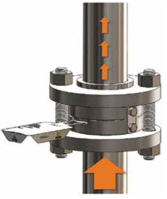
FIGURE 2. Leaks can occur through the relief system if rupture discs become compromised
Corrosion. Rupture discs are manufactured from thin material. End users usually have several disc materials from which they may choose. Material choice is sometimes dependent upon the type of assembly selected. Plants can upgrade from 316 stainless steel to a more corrosion-resistant alloy, such as Hastelloy, without significant increases in cost. Fluoropolymer liners or coatings provide additional protection in many cases. No matter the assembly type in question, proper material specification is critical for corrosive media applications.
Improper installation.Installing a rupture disc in the wrong holder or in the wrong orientation can damage the rupture disc. This can either alter the burst pressure or create potential leak paths. Newer, high-performance rupture discs are sometimes designed to be fail-safe, meaning that in the event of improper installation, the disc will burst at or below the marked burst pressure. Discs not considered to be fail-safe may open at a burst pressure several times the marked burst pressure when installed upside down. The results from an overpressure situation in the above described scenario could prove catastrophic for a plant. Forcing the rupture disc and holder between flanges that have not been opened far enough, or that are misaligned, can create similar issues. Therefore, the selection of a rupture disc assembly that reduces the risk of simple installation errors and requires less training for personnel needs to be considered.
Excess or uneven torque.Excess torque on the holder or flanges can damage the seating surfaces of a rupture disc holder, making it difficult to seal when the rupture disc is replaced. Excess torque can also lead to splitting, wrinkling, tearing or other damage to rupture-disc sealing components in multilayer or composite designs in particular. Angle-seat rupture discs and holders are especially prone to permanent damage due to excess torque. Proper training and tools help prevent this kind of error, as well as emerging assembly types, such as a one-piece unit, that make it impossible for torquing force to damage the rupture disc within its assembly.
Fatigue.Forward-acting rupture discs that have endured multiple excursions close to the set burst pressure can experience fatigue. Over time, this reduces the amount of pressure required to create an opening in the disc, usually resulting in a crack or split rather than a full opening. Such a crack in the disc creates a leak through the system and may cause the disc to activate at a lower burst pressure. This phenomenon, often identified as premature failure, can prove very deceptive to personnel, especially when operating pressures are not continually monitored. High-performance, scored reverse-buckling rupture discs are much more resistant to premature failure due to fatigue.
Physical damage prior to installation. Rupture discs are precision devices made of carefully selected and crafted materials. The materials of construction can be very thin — sometimes just 0.001 in. thick. It is very important that rupture discs are transported and handled carefully to prevent dents, scratches and holes. If a rupture disc is damaged, it should be discarded rather than repaired. Pushing a dent out of a rupture disc, for example, does not restore it to its pre-damaged condition. Most rupture discs can be provided in individual boxes to encourage installation crews to leave them in protective packaging until installation. Employee training in the proper handling of discs will greatly reduce these errors. The specification of fully integrated one-piece assemblies may also offer additional protection for the rupture disc as it is carried by an installer to the application site.
Physical damage due to debris.Rust, grit and debris that may be present on flanges and in piping can cause leaks in a system. Remember, some of the rupture disc components can be as thin as 0.001 in. Compressing a piece of sand or grit into those thin materials can easily create a leak path. Hermetically sealed, fully integrated, one-piece disc assemblies may help to reduce this risk. They eliminate the need to remove the rupture disc from its holder, a process that may allow debris to interfere with the sealing mechanisms.
Leaks outside the planned flow path
In certain situations, rupture discs can leak outside of the planned flow path (Figure 3). Most of the causes listed in the previous sections can lead to process media leaking between the inlet of the holder and the process side of the rupture disc. There is also an additional cause for leakage that is rarely considered.
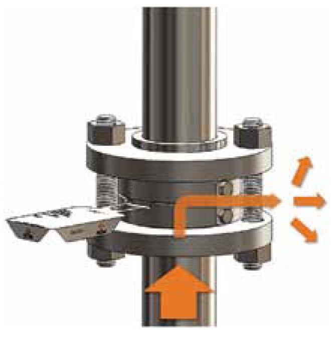
FIGURE 3. Leaks can occur outside of the planned flow path in rupture disc systems if all components are not correctly installed
Some rupture discs are designed and manufactured to include a thicker ring that is spot-welded to the outlet side of the rupture disc. This ring is usually constructed of 0.010- to 0.125-in. thick metal. There are several purposes for this ring. First, it makes the disc more resistant to damage from handling. Another benefit of the ring is its ability to eliminate fragmentation. These rings provide a concentration of stress, or teeth, to assist in the opening of a reverse-buckling scored rupture disc. Finally, the ring provides a more robust attachment point for identification tags.
Placing the heavy ring on the outlet side of the rupture disc ensures that the reduced area on the holder inlet seat seals tightly against the sealing member of the rupture disc prior to the disc opening. However, if the disc is operating under a relief valve and the system remains under pressure after the rupture disc relieves, process media may leak in between the thicker ring and the holder outlet (Figure 4). The thicker ring spreads the sealing force applied by the mating flanges over a larger area on the outlet side of the disc. This leaves the outlet side of the assembly more vulnerable to leakage. Manufacturers offer holders with bite seals on both the inlet and outlet; however, the results are not 100% reliable. The only certain way to prevent this source of leakage is with a one-piece unit offering a hermetic seal.
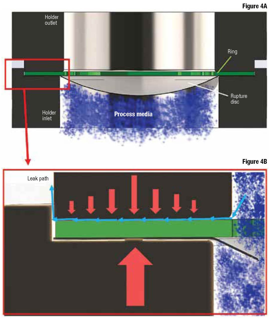
Figure 4. Shown in Figure 4A is a rupture disc with a ring on the outlet. The concentration of stress on the ring (Figure 4B) can make the system more susceptible to leaks outside the planned flow path
Importance of training
Rupture disc installation training is vital to preventing leaks and other types of failures. Some rupture disc manufacturers will set up training at users’ facilities to cover the basics of installation. One may want to design their own basic training course to focus on situations specific to the facility. Relevant topics may include the following:
- Application types, including primary relief, secondary relief or relief-valve isolation
- Rupture disc designs, such as forward-acting, reverse-buckling or flat
- Installation preparation, focusing on safety, cleanliness and holder inspection
- Installing a disc in a holder, considering orientation and side lugs
- Installing rupture disc and holder between flanges, focusing on gaskets and proper torque
When properly specified and installed, rupture discs are a reliable means of protecting plants from overpressure situations and preventing leakage associated with pressure relief valves. Understanding the advantages of the various rupture disc assembly types is vital for preventing leaks while providing overpressure relief. With proper specification, training and maintenance, many of the technologies described in this article can provide satisfactory results. If the application is challenging, or if maintenance, inspection and training levels are not maintained, selecting a more advanced technology, such as a one-piece unit, can offset these deficits. Rupture disc manufacturers can help sort through performance issues and often have training programs available for maintenance staff and installers.
Most importantly, engineering teams can assist with proper specification. Plants with well-trained employees utilizing the best rupture disc technologies will experience peak system performance with minimal downtime related to process leakage. Ongoing innovation efforts in device design continue to increase the reliability, performance and ease of use of these vital safety components.
Edited by Mary Page Bailey
Authors
 Alan Wilson is senior field engineer for Oseco (1701 W. Tacoma, Broken Arrow, OK 74012; Phone: 918-258-5626; Email: [email protected]), a manufacturer of rupture discs and other safety pressure-relief devices. He holds a B.S. degree in mechanical design technology from Oklahoma State University and an M.B.A. from Oklahoma City University. Wilson has been with Oseco for 27 years, serving as an engineering expert in research and development, rupture disc analysis and ASME code. Wilson has earned several patents for his contributions to the Oseco portfolio, and sits on two ASME committees. He has helped to design, build and teach training seminar programs for the proper use, installation and specification of rupture discs in onsite learning events for chemical processing plants and others in the field. Wilson was also on the first team to coordinate with television’s Mythbusters program, when they featured Oseco rupture discs in the first of seven episodes, using them to measure explosion intensity.
 Mike Quimby is a business development specialist for Oseco (same address as above; Phone: 918-259-7124; Email: [email protected]). He holds a B.A. in psychology from the University of Oklahoma and an M.B.A. from Oklahoma City University. Quimby has been with Oseco for 2 years and has 20 years of experience in business development. He has managed hundreds of accounts for chemical processing plants, as well as many Fortune 500 companies.