Quite often, during the design of conveying systems, not enough attention is paid to the design of the conveying pipeline and its components. This disregard often leads to some major conveying system problems such as low conveying rates, conveying line plugging, excessive wear and tear in the conveying line, high conveying system pressure drop, product breakage, fines and streamer generation and product cross-contamination. Guidelines presented in this article help mitigate or avoid such problems.
General considerations
Materials of construction. For the pipe itself, use carbon steel if contamination is not an issue. Otherwise, use aluminum or stainless steel. Use stainless steel for food and pharmaceutical applications. For special applications such as abrasive solids, high temperatures, and so on, it is necessary to find a suitable material for the conveying line and its components.
Pressure rating. Pressure rating of the conveying pipeline should be suitable for the maximum conveying pressure of the conveying system. For most applications with a Roots type blower, a pressure rating of 30 psig is satisfactory. This rating corresponds to the rating of a Schedule 10 pipe. Use thicker pipes, such as Schedule 20, 30 or 40 for higher pressure applications.
Temperature rating. The temperature rating of the conveying pipeline should be suitable for the minimum and maximum temperatures experienced by the conveying line. These temperatures depend upon the ambient temperature, conveying air temperature and solids temperature.
Pipeline joints. Pipeline segments must not be welded to each other because of the need for dismantling of the pipeline. These segments should instead be joined to allow easy dismantling of the pipeline. Flanges can be used, but they are expensive and not easy to unbolt. They should be used where the joint must be 100% leak proof. Use of easy-to-open pipeline couplings is common. Locate the joints for easy access to allow dismantling of the pipeline when necessary.
The inside diameter of the couplings or the flanges must be equal to the inside diameter of the pipe. Both ends of the adjacent pipe segments must be truly aligned with each other so that there is no internal protrusion and there is no gap between the two ends.
Pipeline internal surface. The inside surface should be clean and free of oil and rust. A smooth interior can be used, except when handling plastics that can generate so-called streamers (a product of plastic degradation). In that case, inside surface is roughened by special tools.
For instance, dilute-phase conveying lines in pelleted plastics service are generally roughened on the inside surface to prevent streamer formation. (Other common names for streamers are angel hair or snake skins). Streamers are formed when a plastic particle at a high conveying velocity strikes the smooth pipe wall at a low angle of incidence. The energy of impact is enough to melt the particle surface at the point of contact and leave a thin crayon-like film mark on the pipe wall. This thin film continues to grow in length due to subsequent impacts, cools quickly, and peels off from the pipe wall in the shape of a streamer. The length of this streamer may be a fraction of an inch or two to three feet in length, or even longer. Long thin streamers tend to float and swirl on the air current in storage vessels until they ball up to form something that resembles a bird-nest.
In any case, the net result of streamers is plugged slide gates, feeders, screeners, mechanical conveyers, and hoppers. The best solution to solve this problem is to avoid making streamers, which is done by roughening the inside of the pipeline. Roughening (or scoring) is done by a special shot-peening method, either using inhouse specifications or vendors who have this expertise. Vendors have their own proprietary techniques for applying the scoring. A well scored pipe should last at least one year before it needs to be re-scored.
Aluminum elbows should be anodized to increase the life of scoring particularly when conveying hard or abrasive materials. As an option, stainless steel elbows can also be used depending upon their relative cost.
Although scoring is recommended for conveying systems that handle soft plastics, it has two distinct disadvantages. Pressure drop through the conveying system is higher than that in smooth pipes, and some particle attrition results because of the roughened surface. In pelleted plastics systems, the amount of fines generated is significant. It will then be necessary to elutriate or air wash the pellets at the end of the conveying system.
Static charges. When handling solids that generate a static charge, pipelines must be built to conduct this charge to the ground. Pipeline joints must allow this charge to flow to the ground by using static conducting jumpers across each joint. After assembly of the pipeline, check its resistance to ground, from the beginning to the end. It should not exceed 1 Ohm.
Pipeline supports. Pipes come in standard 20-ft lengths. Therefore, provide supports for the pipeline every 20 ft or less. Locate these supports to prevent any sags in the pipeline due to its weight. After installation, make sure that the pipeline is straight and not sagged. If the pipeline can expand due to high temperatures, design the supports to allow for this expansion. Locate the pipeline so that it has easy access for dismantling.
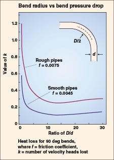
Bends. Material of construction, pressure rating, and temperature rating of the bends should be the same as that of the pipe. Standard short-radius bends are not used in conveying lines because of pressure drop considerations. Studies show that long radius bends have a lower pressure drop. Results from these studies are shown on Figure 1. Long radius bends with a bend-radius to pipe-diameter ratio of 8–10 have a lower pressure drop.
Some vendors have developed special bends such as Hammertek, Vortice Ell, Gamma bend, or blind tees and so on, to reduce product degradation and bend erosion.
Air or gas supply line. Keep the length of this line as short as possible by locating the blower close to the solids inlet or outlet point. Minimize the pressure drop in this line by using a large diameter line if needed. Carbon steel construction can be used, except for in food and pharmaceutical applications. Pressure and temperature rating can be the same as that of the conveying pipe. Provide a check valve in this line upstream of the solids inlet (for pressure type systems), or downstream of the outlet point (for vacuum type systems) to prevent solids from backing-up into the conveying blower.
Diverter valves
Diverter valves are used to divert the flow of solids and air from one conveying line to either of two destinations or from either of two conveying lines into one conveying line. The most critical features of diverter valves are as follows:
• Positive shutoff so that there is no air or solids leakage from the used port to the unused port. This is done by using gas tight seals
• Full port design so that the internal cross-sectional area of the valve is essentially the same as that of the conveying line
These valves are made in various designs but so-called tunnel, channel or plug types are more common. The divert position is at either 30 or 45 deg to the through position. Prefer to use tunnel- or channel-type diverter valves as they will have lower pressure drops.
Keep the pressure rating of the valve the same as that of the conveying pipeline. The pressure rating of the valve housing is generally 150 psig, and the pressure rating of the channel or plug should be the same as that of the conveying line.
To prevent valve seizing, make sure that the valves are designed to operate at the lowest ambient temperature along with the highest internal temperature.
Diverter valves can be operated by hand wheels, T handles, air pistons, hydraulic cylinders or electric motors. Limit switches for the divert or through indicators are installed in many cases to sense the valve position, depending on the degree of instrumentation required for the process. During the time the position of the valve is being changed, it is necessary to shut down the conveying system and clear the conveying line of solids. This time is typically about 15 s.
Material of construction of the valves depends upon the application and solids being conveyed. The most common materials of construction are a cast aluminum body and end plates with a stainless steel plug and stainless steel shafts. Aluminum may be anodized for better wear. Provide seals and packing to prevent leakage through or to the outside of the valve. To prolong life, use stainless steel plugs even if using aluminum conveying lines. This is to minimize abrasive wear of the surface due to high-velocity solids impact. The body can be aluminum or stainless steel.
Valves must be able to divert very fast. A divert time of less than five seconds is desirable.
Diverter valves, flapper type
Flapper type diverters are not suitable for use in pneumatic conveying lines. They are mostly used to control solids flow from low-pressure bins (less than 2 psig). In most cases, solids flow must be stopped by a shut-off valve located above the diverter before changing the flapper position because its position cannot be changed easily if the line is full of solids.
• The valve diameter should match that of the connecting feed chutes
• Use a stainless steel flapper to minimize wear. Housing can be aluminum or stainless steel. The flapper should close fully in either position
• The pressure rating of the valve should match that of the connecting feed chutes
Flexible hoses
Flexible hoses are not used in conveying lines except for short distances, such as in unloading bulk containers like rail cars and trucks. There are several reasons for this. It is difficult to keep flexible hoses in straight horizontal or vertical configuration and they have a tendency to sag and form bends. Their pressure drop is higher than that of pipelines. They also wear out both internally and externally.
Flexible hoses can be metallic or synthetic. Synthetic hoses come with internal spiral-wound metallic liners to improve strength and durability. When conveying static-generating solids, conductive hoses are used. Metal hoses are generally braided stainless steel with a stainless-steel internal liner to prevent air leakage.
Disadvantages of flexible hoses include the following:
• Higher pressure drops than metal pipe due to a higher loss of the solid’s kinetic energy
• Frequent hose failures caused by bending and handling
• Difficulty in manual handling of large diameter hoses (6-in. and above)
• Manual hose connections that are not easily included in process system control logic
Considerations to be considered in hose selection include the pressure rating of the hose, connection methods of flanges and nipples to the hose, considerations of failure consequences, proper static grounding, and minimum bend radius of the selected hose.
Slide gate valves
Guidelines for slide gate valves include the following:
• Use bi-directional, resilient seated valves so that they may close fully even with a head of solids
• Do not use valves with metal seats or internal ledges because solids may accumulate on these ledges, cause difficulty in fully closing the valve and may result in product cross contamination
• For applications that need corrosion protection, use cast, 316 stainless-steel construction for the body and gate
• Body style should be wafer type
• Valve packing should be white square-braid acrylic filament with polytetrafluoroethylene (PTFE)
• Seat material should be white Viton
• The yoke should be stainless steel
• Provide purge gas in the bonnet section to prevent dust buildup inside the bonnet
 |
Design and installation of the slide gate valves should maintain the flow pattern from the bin above. If it is a mass flow bin, the slide valve must maintain mass flow. This requires that the valve’s inside diameter is the same as that of the bin outlet and that the valve is used only in a fully open or fully closed position.
Gas tight designs may be required if the bin above contains gases such as hydrocarbons or nitrogen.
Shut-off and control valves
Shut-off valves, check valves, or control valves are not used in conveying lines to stop or regulate the flow of the solids and air mixture because they interfere with operation of the conveying system.
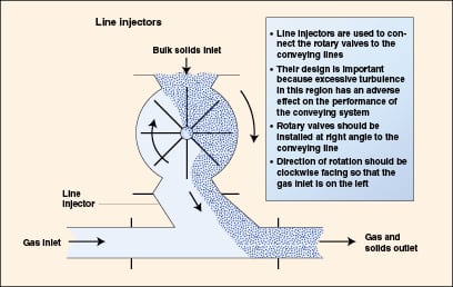
Line injectors. Line injectors are used to inject solids into the conveying line. Figure 2 shows a line injector to feed solids from a rotary valve into a conveying line. This design allows the solids to trickle down into the conveying line instead of falling vertically down and forming a heap.
Route and layout
Minimize pressure drop. Guidelines for minimizing pressure drop include the following:
• Select a pipeline route that is the shortest distance to the destination including both horizontal and vertical lines
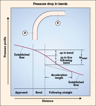
• Minimize the number of bends in the pipeline because bends are a major source of pressure drop. Solids velocity reduces in the bend due to wall friction and impact and then increases in the subsequent straight section of the pipeline, resulting in additional pressure drop (Figure 3 shows the affect of a bend on pressure drop)
• Do not use standard bends because they have the highest pressure drop. Use bends with a bend inside-diameter to bend-radius ratio of about ten. Tests show that pressure drop in such long-radius bends is less than that in smaller radius bends
• Try using diverter valves with a 30-deg. divert angle instead of 45 deg. A 45-deg. divert angle has twice the pressure drop
Maintain conveying velocity. Select a design that maintains the required solids velocity throughout the conveying line to prevent saltation and line plugging. Solids velocity in the pipeline must not fall below saltation velocity to prevent line plugging. This is done by using the following criteria:
• From the pick up point to the first bend, make sure that the conveying line is horizontal and long enough to accelerate the solids to a velocity that is high enough to prevent saltation in the bend. Solids velocity reduces in the bend due to impact and wall friction. This reduction can be 5–50% depending upon the solid. For a 50% reduction, solids velocity entering the bend must be at least 50% higher than the saltation velocity. In general, length of this horizontal line is at least 20 ft, but use a longer line where possible.
• After the first bend, locate the second bend to provide a sufficiently long horizontal line that will allow the solids to reaccelerate to the same velocity as was at the inlet of the first bend
• Do not install bends back to back but at a sufficient distance from each other to allow the solids to re-accelerate
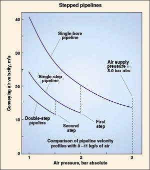
• For long conveying lines, increase the pipe diameter at a suitable point in the pipeline route to prevent very high velocities. Select this point at which the solids velocity does not fall below the minimum conveying velocity. Figure 4 shows a pipeline with two increases in pipe diameter
• Conveying gas can leak from pipe couplings, diverter valves, rotary valves, and other fittings. Use gas tight equipment or increase the supply air flow for these losses
• Avoid using upward sloping pipelines because of loss of solids velocity due to wall friction.
Minimize solids breakage. High conveying velocity results in breakage of fragile solids particles. For fragile solids, this breakage can be proportional to the velocity to the third or fourth power. If this breakage is unacceptable, use a low velocity, dense-phase system or keep the velocity as low as possible.
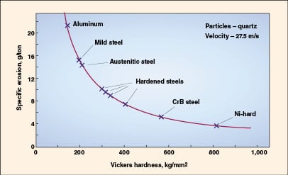
Minimize pipeline erosion. When handling abrasive solids, it is important to use special material of construction for the pipeline to prevent pipeline erosion. Bends in the pipeline are eroded faster than straight pipe. To minimize this problem, use special bends with wear-resistant surfaces, or bends that have replaceable outer backs. Do not use soft materials such as aluminum. Determine the abrasiveness of the solids before selecting a suitable material for the pipeline. Reduce conveying velocity as much as possible, because wear increases to velocity to the 2.5 power or more. If the velocity is doubled, wear increases six times. See Figure 5 for a relationship of this wear between different materials.
Author
 Amrit Agarwal is a consulting engineer with Pneumatic Conveying Consultants (7 Carriage Road, Charleston, WV, 25314; Phone: 304-553-1350, Email: [email protected]). He started his consulting work after retiring from Dow Chemical Co. in 2002 as a senior research specialist. He has more than 47 years of design and operating experience in bulk solids handling and pneumatic conveying. He holds an M.S. in mechanical engineering from the University of Wisconsin-Madison, and an M.B.A. from the West Virginia College of Graduate Studies in Charleston.