Better upfront planning and management can lead to safer, more productive processes throughout every phase of operation
A standards-based approach to process safety — one that actively addresses risks across a plant’s lifespan — can lead to safer chemical processes, fewer safety functions and lower operating costs. The problem, however, is that too few companies employ this approach, and expose themselves to greater risk of a catastrophic incident as a result.
The U.S. Chemical Safety Board (CSB; Washington, D.C.; www.csb.gov) pointed to this problem in a video that examined process safety in the 10 years following the major petroleum-refinery explosion in Texas City. The video cited multiple instances where risks went unaddressed in chemical processing operations, sometimes resulting in fatal incidents. A CSB official also said every incident his organization investigated in the 10 years after the Texas City incident was preventable. “There has not been one investigation we’ve done where we found the incidents were unavoidable,” the official said.
Today, as many companies in the chemical process industries (CPI) look to replace decades-old safety-related technologies, they have an opportunity to put an end to this trend by rethinking their approach to process safety.
Why is process safety falling short?
One problem many CPI companies face is that they simply do not have dedicated resources for process safety. As a result, they are unable to spend sufficient time to help ensure requirements for specifying, designing and implementing a safety instrumented system (SIS), as well as helping to ensure that it is properly maintained throughout its life with functional safety assessments and periodic audits.
A SIS is a system consisting of sensors, logic solvers, such as a programmable logic controller (PLC), and final elements, such as valves, motors and pumps. A SIS is specifically designed to implement one or more safety instrumented functions (SIF). Figure 1 illustrates the role of a SIF within a chemical process.
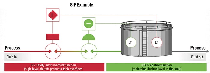
FIGURE 1. A safety instrumented function (SIF) has a specified safety integrity level (SIL) that is necessary to achieve functional safety. The SIL applies to the SIF, which is the combination of the sensor, logic solver and final element — not the programmable logic controller (PLC)
In some cases, companies will specify a certified PLC with a specific safety integrity level (SIL), because it meets their expected highest level of protection. However, they may not apply the same rigor to the field devices, such as sensors and final elements, nor to other layers of protection that are needed for effective process safety.
Another issue is that companies will often strive for compliance when they deploy a SIS, but not ensure the same level of compliance for its functional-safety management aspects throughout its lifespan. For example, they may not proof test the system’s SIFs to make sure that they maintain the target SIL.
Independent reports, such as the U.K. government’s Health and Safety Executive (HSE) report on control system failures, help illustrate where failures are causing or contributing to industrial accidents. The report found that 44% of failures were caused by an inadequate specification, due to either a poor hazard analysis or an insufficient assessment of the impact of control-system failure modes on the specification. Meanwhile, 15% of failures were caused by inadequate operation and maintenance and 20% were caused by changes after commissioning.
Introduced in 2003 by the International Electrotechnical Commission (IEC; Geneva, Switzerland; www.iec.ch), the international standard IEC 61511 is based on a lifecycle approach to process safety. This standard is written to address these known issues with implementation and is largely written by end users, for end users.
Upgrading a SIS Successfully
Recently, a chemical manufacturer created and implemented a new, internal safety standard for its global facilities. The standard was designed to help the company work toward its goal of zero accidents in all areas of its operations.
The company knew it needed to update its decades-old SIS to bring the facilities into compliance with the newly implemented internal safety standards. Several types of risk analyses were conducted to identify compliance levels with the new corporate safety standard. These included conducting safety integrity level (SIL) and hazard and operability (HAZOP) studies at its production facilities. The studies helped the company identify the SIS upgrades needed to bring its facilities into compliance with the new standard. More than that, however, they brought attention to the obsolescence risks faced by some of the equipment used in the facilities.
As a result, the company migrated to a new SIS that brought its facilities into compliance while also reducing downtime risks associated with aging equipment. By staying ahead of current safety requirements, the solution helped the company prepare for future expansion. The systems also helped the company stay ahead of potential SIL requirement increases without the need for another SIS upgrade in the future.
The definitive standard
A methodical and standards-based approach can help companies better understand their process safety risks, then implement the right level of protection. This approach can also help companies design maintenance and support requirements into SIFs to reduce the risk of safety-integrity performance degrading over time.
The functional safety standard IEC 61511 should be the basis for a standards-based lifecycle approach to process safety. It defines the requirements that must be met, not only in designing and implementing a SIS, but also in maintaining it for the entire operating life of the system.
There is more upfront work involved in applying this standard, due to its analysis phase and management aspects. Managing the safety loops throughout a system’s lifecycle also creates more work, but the benefits from this added effort are significant: the likelihood of fewer safety risks, a properly sized SIS and increased process uptime.
Moving through the lifecycle
A lifecycle-based safety approach (Figure 2) has three main phases of execution: analysis, realization and operation, each of which is covered by the specific clauses included within IEC 61511. When moving through these phases, it is important to remember that every task must be verified by someone independent of those who performed the task. These three main phases are further detailed in the following sections.
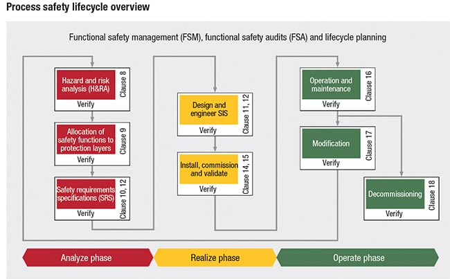
FIGURE 2. International industry standard IEC 61511 can be used to formulate an overarching approach to process safety
Analysis. The purpose of the analysis phase is to understand how much risk exists within the process, and then define where and how that risk can be mitigated. Processes such as the HAZOP (hazard and operability) study identify the risks and generate the safety requirements specification (SRS) and techniques, such as inherently safer designs, alternate layers of protection, alarm management and SIS implementation, to mitigate the risk.
The SRS is a document, or collection of documents, that aim to fully describe the functional and performance requirements for each SIF identified during the hazard and risk assessment. Examples of the details required in this document are:
- The function of each SIF
- The safe state of each SIF
- The expected demand rate, or how often it is expected to operate; and the spurious trip rate, or how often it is expected to fail safely
- The failure modes and behavior of the SIF when faults or failures are detected
- The extremes of environmental conditions in which the SIF operates
Realization.During this phase, a functional design specification can now be developed from the SRS. This document defines how the safety functions defined in the SRS are implemented using selected SIS technology, thus meeting the SRS.
In the design and engineering portion of this phase, technology is selected to help implement the required behaviors. There is no requirement that the technology be certified by groups like TÜV Rheinland (Cologne, Germany; www.tuv.com) and exida (Sellersville, Pa.; www.exida.com), but choosing such solutions can help users meet the required integrity with less documentation. The SIS can then be installed and validated in a documented manner to confirm that it meets the requirements outlined in the SRS.
Operation. Organizations must ensure that the identified and implemented risk-reduction measures are maintained throughout a plant’s or process’ lifespan. This even includes identifying how hazards will be managed during decommissioning.
Safety integrity performance will degrade over time, which is why regular proof tests are critical. Also, any changes to a SIS can impact safety. Clause 17 of IEC 61511 provides guidance for SIS modifications. Modifications to a SIS can occur for several reasons, including the following:
- Failure of a component (such as an I/O module) where the same part number is no longer made by the original manufacturer. This modification could entail fitting a new model or moving signals to another I/O module
- A SIF is not performing up to its expectations. For example, it is failing frequently, and the operating company needs to redesign equipment to get the SIF back to peak performance
- The process plant itself is undergoing modifications, which in turn impact the SIS equipment. This could be as simple as a setpoint change or as complicated as fitting new instrumentation or valves
Verification at each step of the safety lifecycle is essential, as there are many areas throughout the lifecycle when exposure to safety risk is heightened if procedures are not properly followed and verified. For example, during the analysis phase, and specifically during the hazard and risk assessment, if application of safeguards is not quantified — or assumed — or is not specific enough to achieve the claimed risk reduction, it could lead to a situation where a SIF has a risk-reduction target that is less than is actually required. Therefore, the company is operating at a greater risk.
This can happen when a procedure-based safeguard that requires multiple human interactions is poorly written and the people responsible for implementing the safeguard are poorly trained. Another common example of increased risk during the analysis phase is when a “pre-alarm” in the control system is identified as a protection layer and has an inadequately defined operator response or is regularly ignored, or even removed or disabled, because it was originally acknowledged as a nuisance alarm.
One example of an increased risk during the realization phase is when the design team does not correctly follow or verify the requirements defined in the SRS, leading to the SIF not operating as defined by the hazard and risk assessment. This can also occur in situations where the function has been correctly implemented but the producer is mandating a change during the factory acceptance test because, in the producer’s opinion, it is not operating the way it should be operating, resulting in the SIF providing insufficient risk reduction.
Lastly, during the operations phase, similar examples as those listed above can increase safety risks, if not verified. For example, an alarm function identified as a safeguard is removed by maintenance, even if some level of management of change is followed, but the impact analysis for the change did not check whether the alarm removed was specifically identified as a safeguard in the first place.
Decision time
The many CPI companies seeking to replace their decades-old SIS today face a choice: they can continue with the status quo or grandfathering of legacy systems, which assume that what has been providing protection for the last 20 or more years will continue to do so. Conversely, they can take a more proactive, standards-based approach that addresses their plant’s process safety needs across its entire lifecycle. The latter can reduce the potential for catastrophic safety incidents, help to ensure that operations teams are living up to corporate leadership’s expectations for safety and create overall safer and more productive chemical operations. The benefits of this approach are certainly worthwhile, especially in exchange for a little extra planning and management work. ■
Edited by Mary Page Bailey
Author
 Pete Skipp is the global process safety manager for the Systems and Solutions business of Rockwell Automation (4325 W. Sam Houston Pkwy. N #100, Houston, TX 77043; Email: [email protected]). He is responsible for the strategic execution and delivery of safety instrumented systems (SIS) to global process end users across a variety of industries and market segments. Skipp has more than 25 years of experience as a safety systems specialist and 29 years of experience designing, implementing and commissioning process and process safety solutions. He is a Member of the Institute of Measurement and Control (MinstMC) and the IEC61511 and ISA84 standards committees.