With a thorough investigation and proper problem diagnosis, an entire gas plant limited by a deethanizer reboiler circuit was successfully debottlenecked
This article describes a case study of a gas plant (designed by others) that was bottlenecked by the reboil system of a deethanizer stripper. The reboiler system, which consisted of two parallel, once-through thermosiphon circuits, had experienced two different steady-state conditions. One condition had a good split of liquid to each of the two circuits, as is normally expected. However, when operated at relatively low rates, a second, undesirable steady state occurred, with maldistribution between the two circuits, in which one circuit was circulating while the other remained full of liquid. This steady state persisted when tower feed rates were raised until the circulating reboiler reached its heat transfer limitation, still with the other circuit full of liquid.
A variety of troubleshooting techniques — including pressure-drop calculations, close design reviews, examination of operating charts, and gamma scans — led to a correct diagnosis, which enabled debottlenecking of the reboiler circuits and the entire gas plant without any hardware modifications. The desired steady state was established by an operation that, for a short period, generated higher liquid circulation and pressure drop through the reboiler circuits. Once established, the desired steady state persisted when the operation was returned to normal.
Important lessons
A review of this detailed case teaches some very important lessons, discussed below:
- With a parallel reboiler system, maldistribution between parallel circuits does occur and can cause severe bottlenecks (To the best of our knowledge, this is the first time that such maldistribution is reported in the literature).
- Pressure balances need to be considered at the design stage, not only for the maximum design rates, but also for the minimum expected operation rates
- It is important to provide flexibility in once-through reboiler systems that will permit operation as a circulating thermosiphon system, at least at low rates
- Good troubleshooting can provide low-cost (in this case, no-cost) debottlenecking of an entire gas plant
Process description
This newly built gas plant was bottlenecked by its deethanizer stripper. The tower bottleneck appeared in the reboiler circuit. In early April 2014, the author’s company (which had no involvement in the tower or reboiler design, but has extensive experience in distillation design and troubleshooting), was requested to assist with investigating the root cause of the bottleneck and to find ways to overcome it.
A task force, including process and operation engineers from the operating company and Fluor’s distillation specialists, was created. The joint team identified the root cause. Based on the root cause, a solution was successfully implemented. After this the deethanizer stripper and gas plant were returned to full operation, achieving the design rates. Described below is the troubleshooting investigation that was carried out, and the lessons learned.
The deethanizer stripper is a tower that is 15 ft, 6 in. in diameter. It is equipped with four-pass conventional valve trays with moving round valves. The tower base contains a preferential baffle that divides the bottom sump into a separate reboiler-draw compartment and a separate bottoms-draw compartment. Liquid leaving the bottom valve tray is diverted to the reboiler-draw compartment (Figure 1). From there it flows into a battery of four horizontal thermosiphon reboilers. The liquid from the bottom tray is diverted to the reboiler-draw compartment by notched-bottom seal pans.
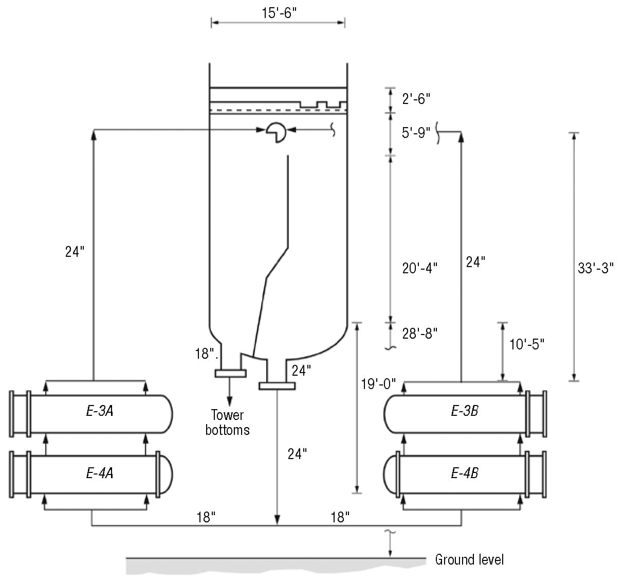
Figure 1. Shown here are the deethanizer stripper A and B reboiler circits. The lower reboiler in each circuit (E-4A or E-4B) is heated by hot naphtha, the upper reboiler (E-3A or E-3B) is heated by high-pressure steam
As shown in Figure 2, the 8-in.-deep notches in the seal pans are located right above the reboiler-draw compartment. There are no notches above the bottom-draw compartment. The purpose is to feed all the bottom-tray liquid to the reboilers.
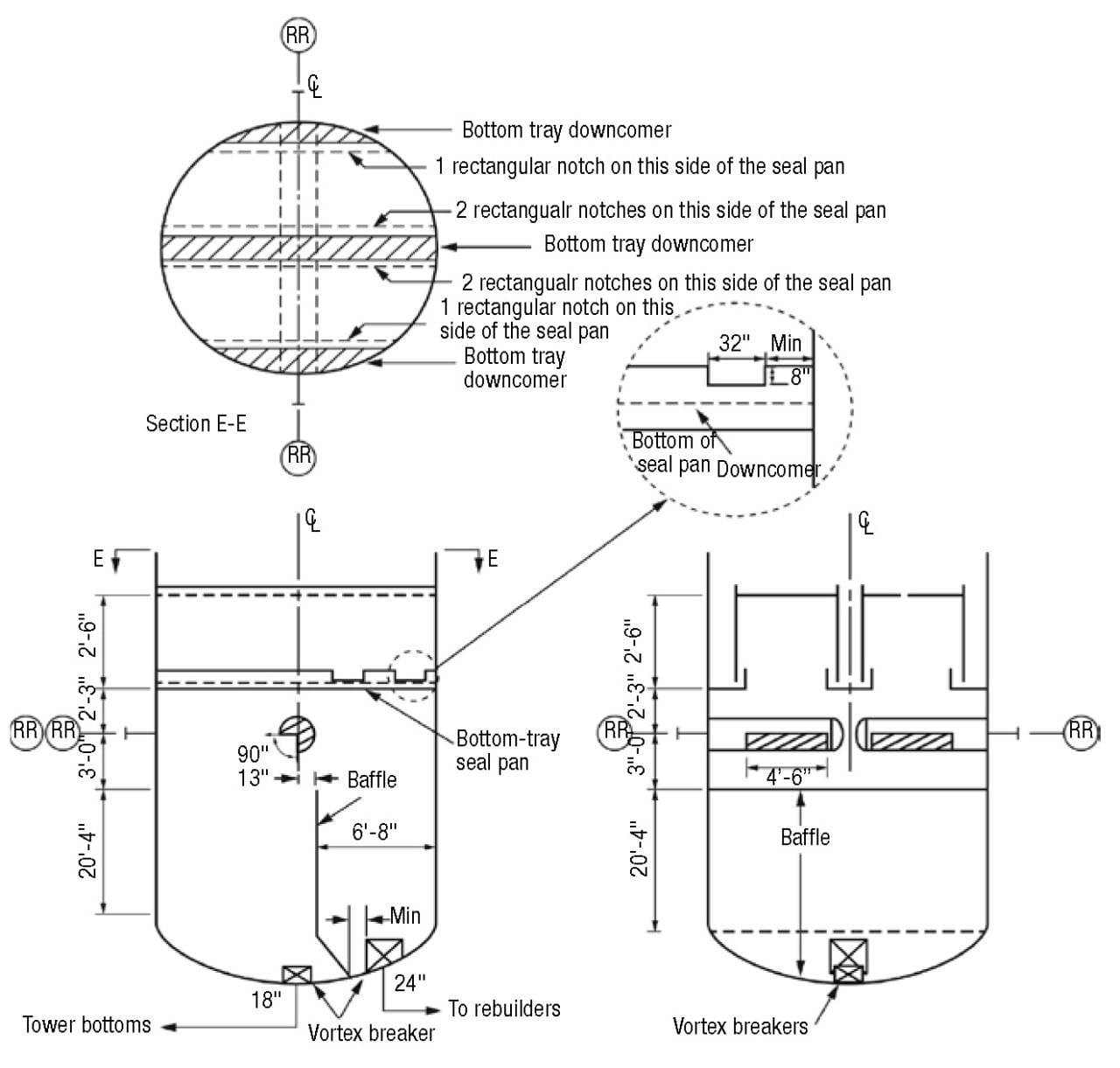
Figure 2. As part of the deethanizer stripper tower base geometry, a preferential baffle divides the tower bottom into a reboiler draw sump and a bottom product draw sump. All of the liquid from the trays is directed into the reboiler draw sump via a notch arrangement, while all the liquid returning from the reboilers is directed toward the bottom product draw sump via cutouts in the reboiler return pipes
The vapor-liquid mixture returning from the thermosiphon reboilers enters above the bottoms-draw compartment via two opposite 24-in. nozzles. Each nozzle is equipped with a pipe that extends to close to the centerline of the tower and has a cutout that measures 4 ft, 6 in. in the bottom quadrant. Both cutouts are directed toward the bottoms-draw sump (Figures 1 and 2).
The purpose is to have all the reboiler-return liquid enter the bottoms-draw compartment, and to have none enter the reboiler-draw compartment. The vapor returning from the reboilers ascends to the bottom tray, while the liquid returning from the reboilers descends to the bottoms-draw compartment.
This design generates a once-through [ 1] thermosiphon reboiler system. Such a system intends to capture all of the liquid leaving the bottom tray and feed it directly to the reboiler. The reboiler-return liquid is entirely drawn as bottoms product. None of the reboiler-return liquid is recycled back to the reboiler — hence the name “once-through.”
Once-through systems can achieve one full theoretical stage of separation, if the trapout tray and draw pan do not leak [ 1]. With the cold bottom-tray liquid being fed to the reboiler, it can also maximize the reboiler temperature difference and capacity. Reboil vapor is limited to about 40% of the bottoms-product rate, due to the normal limitation of 30% maximum vaporization (by weight) in thermosiphon reboilers [ 1]. This makes once-through thermosiphon systems appropriate only for low-boilup systems, such as strippers. Many deethanizer-strippers use once-through thermosiphon-reboiler systems.
This deethanizer stripper has four horizontal reboilers, arranged in two parallel circuits, A and B (Figure 1). In each circuit, the lower reboiler ( E-4Aor E-4B) is heated by hot naphtha liquid, while the upper reboiler ( E-3A or E-3B) is heated by high-pressure steam. In each circuit, the naphtha and steam reboilers are designed to provide duties of 32 million Btu/h and 40 million Btu/h, respectively.
On the boiling side, liquid to the reboilers is provided from the reboiler-draw sump, via a 24-in. pipe that splits into two 18-in. pipes, each going to one circuit. The reboiler effluent from each circuit returns to the tower via a 24-in. line.
Initial performance
During the startup, the plant was at low rates and to improve tower stability, it was decided to take the steam out of reboiler E-3A. This was successful at creating a steady steam flow through the E-3B reboiler circuit and provided tower stability, but the plant has been unable to re-establish flow through the E-3A/E-4A set of reboilers ever since. For the next six months or so, the E-3B/E-4B circuit did all the reboiling, while the deethanizer-bottoms liquid circulation had been difficult to establish through the E-4A/E-3A circuit.
Figure 3 shows typical operating data from six months after start up and compares them to the design values. The zero-steam flowrate through E-3A and the absence of significant temperature difference across the heating side of E-4A indicate no boiling and no significant circulation through the A circuit. To maximize duty, steam to E-3B was raised to the maximum, well above the design steam rate for this exchanger, but still not high enough to make up the lost duty of E-3A. This restricted the feed flowrate through the tower and bottlenecked the entire gas plant. There was a need to get the stripper-bottoms liquid to start flowing through the E-4A/E-3A circuit.
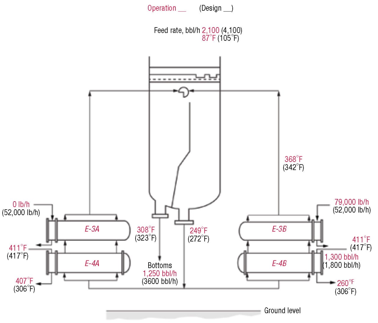
Figure 3. This figure shows the deethanizer stripper base, operation versus design. The zero-steam flowrate through E-3A and the absence of significant temperature difference across the heating side of E-4A indicate no boiling and no significant circulation through the A circuit
Troubleshooting
Initial troubleshooting efforts focused on initiating flow through the A circuit by inducing a gas lift. One possibility was that the light components were stripped out of the A-circuit reboilers, leaving behind heavy hydrocarbon liquid. Heating this heavy liquid may not have produced enough vapor to initiate reboiler action. Injecting a light gas, such as nitrogen, could possibly gas-lift the heavy liquid and initiate thermosiphon circulation. This technique has been successful in the past for initiating circulation in liquid-full thermosiphon reboilers [ 2–4].
A source of nitrogen was connected to a bleeder valve immediately downstream of E-3A. Nitrogen was injected for 4–6 hours in an attempt to provide lift and jump-start the thermosiphon effect. This action was unsuccessful in initiating circulation through the A circuit.
This came as a surprise, as in other reboilers [ 2–4], a similar action had been successful. There were questions as to whether enough nitrogen was applied, whether it was applied at the correct point, and whether the liquid in the reboilers was just too heavy and needed to be drained and replaced by fresh liquid before the gas lift attempt. Addressing these problems would have required some painful modifications or operations with no assurance of success. The validity of the theory — that heavy liquids in the A-circuit are the root cause — was questioned. With these considerations in mind, the investigation team decided to perform more troubleshooting before trying out a fix.
One useful reference point was process data from the very initial operation of the stripper. The operating charts from shortly after initial start up (Figure 4), at a stripper feedrate of about 1,700 barrel per hour (bbl/h), show both the A and B circuits operating simultaneously and stably. Both E-3A and E-3B reboilers operated stably with a steam flowrate of about 32,000 lb/h to each. For both the E-4A and B reboilers, the temperatures of naphtha entering and leaving were about 400°F and 320°F, respectively. At time 22:40 hours, the stripper feedrate plunged, steadying at about 1,200 bbl/h 40 minutes later.
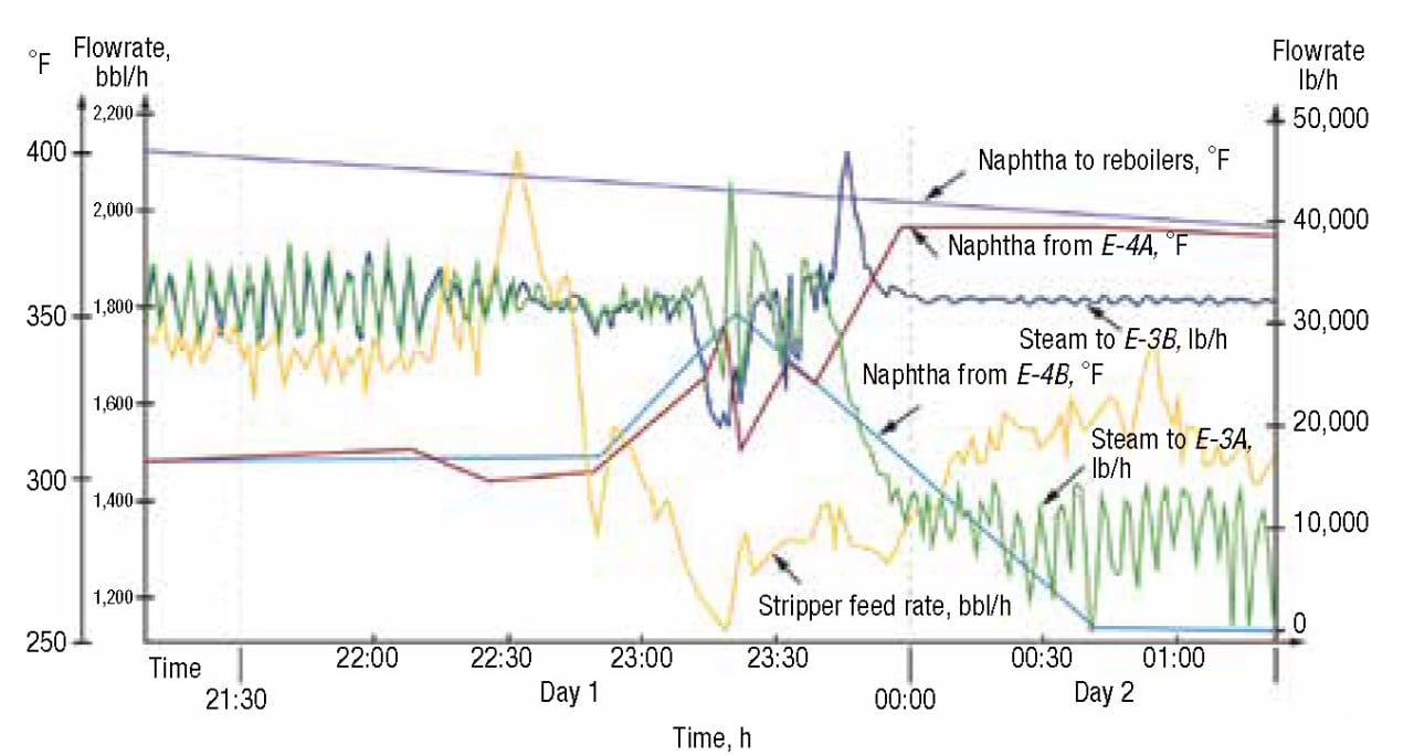
Figure 4. Shown here are the process data for the very initial operation of the stripper-reboiler circuits. Before 23:00 hours, both circuits operated simultaneously and stably with the same steam flows and naphtha temperature differences for each circuit. After 0:00 hour, the steam rate to E-3A dropped and the temperatures of naphtha entering and leaving E-4A became the same, suggesting boiling and circulation in the circuit had stopped
To improve stability, the plant manually reduced the steam flowrate to E-3A, to about 8,000 lb/h, with the steam rate to E-3B remaining at its previous value. The naphtha temperatures into and out of E-4A became the same, about 360°F, suggesting it had stopped heating.
At the same time the temperature outlet from E-4B decreased to about 260°F, suggesting that this reboiler was working harder than before. Both of these occurrences suggest that the A-circuit stopped circulating. Early on the next day, the feedrate to the stripper rose again, to 1,500 bpl/h, but this time the A circuit remained inactive. It was common practice to attempt to restart circulation by opening and closing the steam valve on the stalled set, but circulation remained stalled.
This sequence of events suggests the possibility of the existence of two hydraulic steady states, with an easy switchover from one to the other. This is likely to take place when the reboiler pressure drop on the boiling side is low.
Pressure drop
Calculations performed during the design by the engineering contractor that designed the circuits showed a total pressure drop of 1 psi for the exchangers in each circuit at design conditions. The contractor’s calculated pressure-drop values were 0.4 psi and 1.3 psi for the reboiler-liquid inlet line and the reboiler-return lines, respectively. The total pressure drop is equivalent to 11 ft of liquid head.
Figure 1 shows the elevations of the reboiler circuits. The diagram shows that not much liquid head is required to overcome the pressure drop in the reboiler circuit. The liquid level in the reboiler draw compartment will therefore be near the bottom of the compartment, even at the design rates.
At the low rates, the pressure drop will be lower still, and the liquid level will drop further, possibly dropping out of the reboiler-draw compartment into the reboiler-liquid-inlet pipe. Further, at low boilup rates the bottom tray may weep, sending liquid directly into the bottom draw compartment, and causing the liquid level to be lower still.
At a low liquid head, fluids tend to form their favorite flow patterns. Two steady states can form:
- One with operation of the two reboilers simultaneously, as intended
- The other has all the boiling taking place in one circuit, and the other circuit filling with liquid to the same height as the liquid in the reboiler liquid inlet pipe
Once the latter steady state forms, the steam that is still going in (the 8,000 lb/h going to E-3A after midnight on the second day, as shown in Figure 4), will strip the lights out of the near-stagnant liquid. Before long, heavy liquid will form in this circuit, and this liquid will be difficult to boil. This situation will stabilize this steady state and it will persist.
The proposed theory states that the liquid level in the reboiler compartment would be very low, possibly absent, and will not approach the overflow baffle. This can be easily tested using gamma scans. The tower base was gamma scanned, both on the bottom compartment side and on the reboiler compartments side. In addition, neutron-backscatter scans were performed to confirm or deny the gamma scan results.
The gamma and neutron scans showed the following:
- Nothing abnormal showed up on the inner active area scans for the bottom six trays. Other trays were not scanned
- Both the gamma and neutron scans showed that the liquid level in the bottoms-draw compartment was 10–12 ft above the tangent line. This was the same as the level indicated by the level instrument
- Both gamma and neutron scans had difficulty finding a liquid level on the reboiler-draw compartment. There definitely was no liquid level above the bottom tangent line. The gamma scans showed some absorption at the tangent line, about the same absorption as the froth on the trays, but this could have been due to the welds at the tangent line. The neutron scans showed no liquid at all in the reboiler-draw compartment
The absence of liquid level in the reboiler-draw compartment gave strong support to the “two steady-states” theory.
Solution
With the theory verified, the challenge was now shifting from the steady state with the stagnant A reboilers, back to that of the two reboiler circuits operating simultaneously.
In a circulating thermosiphon reboiler (as distinct from a once-through thermosiphon, such as the stripper reboilers), increasing the liquid head in the tower base generates more liquid circulation through the reboiler circuit and reduces the fractional vaporization [ 4]. Considering the pressure balance and assuming a constant heat duty, the higher liquid head supplied to the reboiler is matched by the additional friction head due to the enhanced liquid circulation rate plus the additional static head due to a higher amount of liquid in the reboiler shell and outlet line.
Extending this reasoning to the stripper reboilers, generating liquid circulation and increasing the liquid head in the reboiler-draw compartment will raise the pressure drop through the active reboiler circuit. This higher pressure drop will induce some of the liquid to follow the easier path (that is, the path with less pressure drop) through the inactive reboiler. Once this liquid is heated, it will start boiling, and the thermosiphon will be established in the previously inactive circuit.
One way to generate circulation and increase the level in the reboiler-draw compartment is to raise the level in the bottom-draw compartment until it overflows the baffle, and keep the bottom-draw compartment full during the circulation. The risk is that the liquid level may ascend to the trays and cause flooding and possible damage there. It is important to avoid excessive buildup of liquid up the tower.
In principle, the level transmitter can be watched during the operation to avoid excessive liquid level. This was difficult in this deethanizer stripper. Since the reboiler-return pipe is only 2 feet above the baffle (Figure 2), and the vapor from the reboiler return blows downward, causing a frothy dispersion, the frothiness may reduce the specific gravity and lead to an optimistically low level measurement. Also, the high tap of the level transmitter is just less than 2 feet above the baffle, which may make it difficult to see when the level rises toward the trays. Fortunately, there is a differential-pressure transmitter across the stripper that comes from the upper tap of the level transmitter and therefore can monitor any accumulation of liquid above the upper tap.
The plan was to raise the liquid level in the bottoms-draw compartment to the level of the reboiler return, an increase in height of about 20 ft. When the level was first raised, it was controlled using the differential-pressure transmitter. Subsequently, a pair of electronic pressure gages was added to the reboiler side of the column to monitor the level directly, and an additional gage was added to the product outlet line to monitor the level on the bottoms-draw side of the baffle. In order to avoid damage due to entrainment of liquid through the trays the differential pressure across the bottom trays was closely monitored.
To raise the level on the reboiler side of the baffle, the bottoms-draw side liquid was overflowed to the reboiler side, by reducing the bottom-product flowrate. The level rose until it reached the top of the baffle when it “flat lined” as it overflowed.
After one hour of overflowing the baffle, the level had increased on the reboiler side by 13 ft. At that time, the following two process indications provided evidence that the A side reboilers were starting to circulate liquid:
- A rapid decrease in steam consumed by the
- 3B reboiler suggested a decrease in liquid flow to the B side reboilers; and A rapid decrease in 4A hot-side outlet temperature suggested an increase in duty in the 4A reboiler
Steam was quickly opened to 3A to ensure we maintained A side reboiler circulation. Almost immediately, even split and duties were confirmed between the A and B side reboilers. The bottoms-outlet flow was increased to stop overflowing the baffle, and the bottoms level was returned to normal.
The 13-ft level increase was probably not enough to get the level of weathered liquid (the liquid that was sitting in the A reboiler circuit for a lengthy period) up to the reboiler-return nozzle on the tower. But the fresh liquid that had entered the reboiler as the level was being raised provided enough vaporization to gas-lift the weathered naphtha into the tower and start the circulation.
The column remains prone to losing reboiler duty. This is believed to be because a portion of the bottom-tray liquid bypasses the reboiler side of the baffle. The bottom tray is an active tray. It remains unclear whether the tray weeps enough liquid to cause the problem, or whether some of the liquid directed to the reboiler-draw side of the baffle falls into the bottoms-draw side of the tower base. To fix this in the future, the bottom tray will be replaced with a total trapout tray to ensure all bottoms liquid must pass through the reboilers.
Until the plant gets to an opportunity to install the chimney tray, the reboiler continues to stall periodically, so raising the liquid level has become a standard procedure that has been executed several times since by the operations team, to regain lost reboiler circulation.
Lessons learned
The investigation described here highlights the importance of good troubleshooting and problem diagnosis for overcoming bottlenecks. In our case, pressure-drop calculations, close design reviews, detailed examination of operating charts, and conducting gamma scans led to the correct diagnosis, which enabled debottlenecking an entire gas plant with no hardware modifications.
Maldistribution between parallel reboiler circuits has received little attention in the literature, with no published case studies identified by Kister’s survey [ 2]. To the best of our knowledge, this is the first time this type of experience has been reported. This maldistribution is especially severe at low rates, when the pressure drops in the reboiler circuits are low. Due to the low pressure drop, the fluids find their favorite pathways and steady states, and can easily swing from one steady state to another — promoting instability. With parallel reboiler circuits, careful analysis of the pressure balance both at the normal- and reduced-rate operation is important, and should be performed at the design stage. This case demonstrates that increasing the pressure drop in these circuits can help route the fluids to the preferred pathways and counter this maldistribution.
Baffled systems have their benefits [ 1], but can also generate or amplify hydraulic problems; thus they need to be designed carefully. In the case of the deethanizer stripper, the baffle was far taller than it needed to be. Had it been even a couple of feet shorter, it would have been easy to raise the liquid level in the bottoms compartment above it and achieve better operational flexibility.
It is important to provide flexibility when designing once-through thermosiphon circuits. As pointed out [ 1,2,4] they can be quite troublesome, and adding simple features that can convert them temporarily to circulating thermosiphon circuits can go a long way toward easing startups and avoiding process bottlenecks.
References
1. Fractionation Research Inc., Design Practices Committee, Reboiler Circuits for Tray Columns, Chem. Eng., January 2011, p. 26.
2. Kister, H.Z., “Distillation Troubleshooting,” Wiley-Interscience, 2006.
3. Kister, H.Z., T.C. Hower, Jr., P.R. de M. Freitas, and J. Nery, “Problems and Solutions in Demethanizers with Interreboilers,” Proc. 8th Ethylene Producers Conf,. New Orleans, La., 1996.
4. Kister, H.Z., “Distillation Operation,” McGraw-Hill, N.Y., 1990.
Author
 Henry Z. Kister is a senior fellow and director of fractionation technology at Fluor Corp. (3 Polaris Way, Aliso Viejo, CA 92625; Phone +1-949-349-4679; Email: [email protected]). He has over 30 years experience in design, troubleshooting, revamping, field consulting, control and startup of fractionation processes and equipment. He is the author of three books, the distillation equipment chapter in Perry’s Handbook, and more than 100 articles, and has taught the IChemE-sponsored “Practical Distillation Technology” course more than 450 times. A recipient of several awards, Kister obtained his B.E. and M.E. degrees from the University of New South Wales in Australia. He is a Fellow of IChemE and AIChE, member of the National Academy of Engineering (NAE), and serves on the FRI Technical Advisory and Design Practices Committees.