Plant layout is as important a part of process plant design as it ever was, but it is rarely taught as part of chemical engineering courses
While process plant layout is a critical aspect of chemical process industries (CPI) operations, the majority of the seminal works in this area have been published in trade journals [ 1–10] or classic texts such as Perry’s Handbook [ 11]. Too often, process plant layout is covered in only a cursory fashion in the engineering curricula; as a result, much of the knowledge of how to lay out process plants resides in the heads of engineers who are nearing the end of their careers. This article was developed from a recently updated book on process plant layout by the author [ 12].
Good plant layout is as important as ever today. A recent study by Kidam and Herme [ 13] showed that 79% of process plant accidents involved a design error, and the most common type of design error leading to accidents was poor layout, as shown in Figure 1.
![FIGURE 1. In this study of design errors that occur most often in the CPI, plant layout emerges as the most prominent factor to blame (Reprinted with permission from [14])](https://www.chemengonline.com/wp-content/uploads/2016/12/15.jpg)
FIGURE 1. In this study of design errors that occur most often in the CPI, plant layout emerges as the most prominent factor to blame (Reprinted with permission from [14])
This article reviews the common terms and discusses the basic methodology for sound plant layout.
What is layout design?
The discipline of layout design refers to that part of process-plant design that determines how the equipment and supporting structures needed for a process — along with their interconnection by means of pipes, ducts, conveyors, vehicles, wired or wireless connections — are to be laid out. Layout designers have to satisfy several key criteria to ensure that their designs do the following:
- Ensure reliable and safe plant operation
- Provide safe and convenient access for maintenance of items, and for the removal or in situ repair of components or process equipment
- Ensure acceptable levels of hazard and nuisance to the public
- Provide adequate levels of security to protect against the risk of crime, vandalism and, potentially, terrorism
- Facilitate safe and efficient construction
- Realize effective, economical and ergonomic use of space
- Demonstrate compliance with local planning regulations regarding aesthetics
- Ensure compliance with U.S. Environmental Protection Agency (EPA) or equivalent requirements
- Demonstrate compliance with any other relevant codes and standards
- Guarantee that the supply of services to the plant and access to the periphery of the plant for maintenance, construction and emergency services are supported by the location and layout of the site
On a new “greenfield” site, the layout design will need to reflect the known needs of the process plant or process units to be constructed. Alternatively, a plant may be placed on a number of plots on an existing “brownfield” site.
In the latter case, it is a common scenario that requirements of the newer plant may not have been foreseen at the time of the original site layout. As a result, at least some of the access arrangements that would normally be provided on a new site will have to be provided post hoc by the layout designers. Existing access arrangements may need to be reconsidered to suit the evolving inter-relationships between the existing site and the new plant or equipment.
Site, plot and equipment layout
There is widespread disagreement about what the terms site, plot and equipment mean. This article attempts to standardize the description and use of these terms to avoid confusion, following the naming convention set forth in Ref. 12.
In a brownfield situation, layout designers have to consider three separate things:
Site layout — How plots relate to each other within the overall site, and with other activities outside the site
Plot layout — The consideration of how process units relate to each other’s disposition within a plot
Equipment layout — The consideration of the arrangement of process units and associated or attendant items around a process unit
This article, and the book on which it is based [ 12], do not use the term “plant layout” for any of these activities, as it is loosely used to describe several of them individually and several combinations of them. Rather, we define a “plant” as being the whole collection of equipment necessary to make a product.
In traditional chemical process plants, an ideal site would be split up into individual plots by its principal road system, with additional access roads provided for the larger plots. However, in many sectors, plants may not be big enough to have such a road system. A complete set of individual process units (known as a plant) may fit onto a single plot, although larger plants may need two or more plots, and a site may contain a number of plots.
Process plant (or more simply plant). A process plant is defined as “a complete set of process units and direct supporting infrastructure required to provide a total operational function to produce a product or products…”
Plot layout. Plants may be arranged across a number of plots, to include “an area of a site most commonly defined as being bounded by the road system…” Plots are shown in aqua in Figure 2. (Note: The term plant is sometimes used by practitioners synonymously with plot, reflecting the reasonably common occurrence where a plant occupies a single plot.)
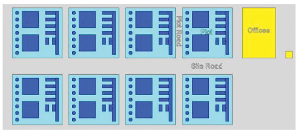
FIGURE 2. This figure illustrates, in simplified form, a process production facility or “site” (A site, depicted here by the grey box, is defined as “…bounded land within which a process plant sits”). A site may contain a number of process plants (which themselves may occupy several plots, each of which typically contain many types of equipment), as well as non-process plant and buildings
Piping layout. Within the discipline of layout design, a distinction is commonly made between piping layout (defined as “the layout of piping and associated support systems…”) and equipment layout (defined as “layout at the level of a single process unit and associated ancillaries”). Both of these disciplines are often referred to colloquially as plant layout.
Initially, plot layout involves mainly equipment layout, and piping layout comes in later, at the detailed design stage. Plot layout often occurs in the context of a “masterplan,” that aims to define the site’s overall design intent, especially if architects are involved. In such cases, it may be important to follow the architect’s approach to site and operational layout through the use of masterplanning (an approach outlined in Ref. 12, Appendix E).
How to lay out process plants
One can identify six broad layout philosophies (the first one is less formal, and the other five are based on more formal methodologies):
Intuition based on experience. Using this approach, an experienced plant layout designer simply permutates and combines configurations that have been used successfully in the past, analyzing and evaluating the resulting combinations
Economic optimization. Such efforts typically aim to minimize distances traveled by materials; this approach is particularly well suited to be incorporated into software. This approach also clearly relates to the first approach
Critical examination. This approach, similar to HAZOP, was recommended by Mecklenburgh [14] but never taken up by practitioners. It might, however, have value in academic settings
Rating— Rating approaches assign values to equipment, plots and so on, from the point of view of interconnectedness, various hazards and more, in order to allow grouping and separation relationships to be generated
Mathematical modeling. There are a number of academic approaches based on this, but they are currently at an early stage of development
Software-based approaches. Modern 3-D CAD software often includes programs to develop a rough layout of pipework once the equipment location is specified
For any given project, several of these approaches are often combined in various ways in different sectors, and such combinations vary among layout designers of different disciplines.
A formal technique is any logical method that provides definitive information on relationships between items or numerical data on spacing distances. It must be based on a procedure that is adequately defined and recorded and can be examined and criticized.
Before starting a layout, the relevant information should ideally be assembled. Such information typically includes process and site data, regulatory and contract requirements, company and other recognized codes of practice. Often, not all such data are available at the start of a project. To avoid delays and to provide a starting point, it is useful to have information on typical spacings. However, it is emphasized that such spacings are rough and must be confirmed or replaced later by the proper project data or design.
A first layout is almost always based on process flow. Intuition drawn from experience indicates that such a layout is basically a good one and can be altered successfully to accommodate the specific requirements of operation, maintenance and safety. The intuition (and experience) of the engineering design team usually indicates immediately what the principal alterations to this default case should be. Thereafter, the formalized methods shown in the bulleted list above should be used to finetune and improve the preliminary design that was put together based on the initial intuitive approach.
Historically, formal layout methods, mainly developed within the CPI, have tended toward optimization for minimum capital cost. However, the impetus for developing formal layout methods was generated by the changing attitude of society toward the CPI, and to the consequences of accidents in CPI operations.
Although safety has always been a major constraint in plant layout, its most visible effect on the layout was typically related to relatively simple rules for spacing and electrical zoning in accordance with codes of practice. The adoption of more dangerous processes, the increasing scale of plants and associated chemical storage, and the shortage of skilled staff, coupled with greater public concern, have required companies to be able to justify the reasons for selection of a given layout to a far greater extent than was necessary in the past. Today, engineering teams are required to develop and maintain records of potential problems, alternatives that were considered (with supporting data) to justify design decisions to satisfy prevailing legislation and to support a legal defense in the event that problems arise later.
There are still very few formal layout techniques available to the designer, and none can completely replace the designer’s abilities either to conceive new solutions or to evaluate alternatives. As with all engineering, plants built without experience and intuition are “bad plants.” The intuitive approach is tested and corrected as the result of using other formal techniques along with more experience. Computer-aided techniques can supplement but not replace engineering by experts.
Formal techniques reported appear to aim at one or more of three main objectives:
When used to supplement or verify the designer’s experience, the formal techniques available today are able to improve the layout and provide rational justification of layout decisions.
Ref. 12 discusses ten formal approaches to plant layout that are widely followed by chemical engineers, piping designers and process architects in different CPI sectors. The approach discussed below is a modified Mecklenburgh method [ 15], adapted from that given by Mecklenburgh in the first edition Ref. 14.
- When considering a greenfield site, the development typically follows this sequence (each of the steps is described briefly below): Preliminary plot layout (Steps 1–9)
- Preliminary site layout (Steps 10–15)
- Design sanction, possible site purchase
- Detailed site layout (Steps 16–17)
- Detailed plot layout (Steps 18–19)
However, existing brownfield sites (with their pre-existing conditions) will impose particular constraints, so some of the following site-layout steps may not be needed.
The layout methods described below suggest a highly formalized, structured, rigorous and frankly, expensive process. The version of the layout process suggested here is typically only appropriate to the largest process plants. Professional judgment is required to understand how much of this approach is appropriate, given the site-specific requirements and constraints of the project being considered.
Preliminary plot layout
Step 1. Plot data. The data needed at this step include preliminary process flow diagrams (PFDs) and piping and instrumentation diagrams (P&IDs), which must show the size of major pipework and suggested elevations of major equipment), process engineering design for the equipment (such as size and shape), the results of preliminary hazard assessments of the flowsheet, and the codes of practice to be followed in the plant design.
Step 2. Plot layout. The layout is made using the data gathered in Step 1, in the sequence of the process flow using the experience of the engineer to recognize constraints, such as major piping and cabling. Typical layout spacings (described in Ref. 12, Appendix C) are useful at this stage. Simple drawings and cutouts are typically employed.
Step 3. Elevation. The elevation assumptions in the flowsheet should be questioned. This enables the process objectives and constraints on elevation to be defined. Various alternative elevation arrangements are generated, possibly by using formal techniques, such as travel and correlation charts.
The cost of each potential elevation alternative is examined, primarily for differences between, for example, the number of plant items needed to achieve the objective, or differences in the material-transfer costs, such as piping, pumping required to elevate items and power consumption.
Simple elevation drawings can be prepared showing only heights and relative positions of items, but structure and floor levels are not introduced at this point.
Step 4. Plot plan. Plant items, buildings and principal pipe and cable runs are laid out in a plan, to ensure that the obvious layout constraints (operation, maintenance, construction, environmental, safety and drainage areas) are accommodated. Cutouts are helpful at this stage. A cost assessment is made of each competing arrangement being considered. The more promising arrangements may be optimized to produce even more economical layouts.
Step 5. Plot buildings. Housing CPI plants inside buildings is more expensive than having plants in the open, even for plants on elevated structures. The need for enclosed buildings specified in the process design should therefore be examined critically.
Step 6. Plot layout. The selected plan and elevation layouts are now combined with building studies to determine possible positions of support and access structures, and to study civil requirements (such as foundations). These may force relaxation of earlier constraints. The layout alternatives are usually presented as 2-D drawings, though 3-D computer models may also be used (Figure 3).
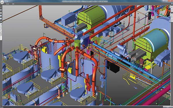
FIGURE 3. The output of a typical 3-D plant layout model is shown here. This model of a solids-handling facility was produced using CADWorx from Intergraph
These models will help both the layout designer and other disciplines to visualize functional and safety aspects. Consequently, it is useful at this stage to have brief and mainly intuitive reviews of the layout be carried out by the various disciplines.
Cost evaluations are carried out again or finetuned for the acceptable layouts and a short list of particular layout arrangements is developed and recorded as plot plans (ideally just one selection is chosen, but in some cases, competing options are still on the short list).
Step 7. Hazard assessment of plot layout. Areas within the plot where loss of containment can occur must be identified, and the amount of materials that could potentially be lost must be quantified by analyzing various potential hazard scenarios. The consequences of each loss with respect to explosion, fire or toxicity should be calculated.
Within the plant, these calculations will indicate separation distances between potential sources of ignition and sources of leaks and will specify the various hazard zones for electrical equipment and fired equipment. The safe positioning and protection of control rooms will also be calculated. These calculations are also essential to assess and predict the potential losses that could occur at various distances outside the plot, with regard to the danger to people, equipment and buildings from fire, explosion and toxicity. The layout may well have to be adjusted.
The Mond Index method [ 15] may be used prior to (but not instead of) the above assessments.
Step 8. Layout of piping and other connections. The principal piping and pipe routes are confirmed during this step. Principal electrical mains routes are also checked. Various connecting arrangements are considered and the most promising ones are further optimized. Piping models can be used as aids and computerized versions can be used to support optimization efforts. The best layout arrangement should now be selected and recorded.
Step 9. Critical examination of plot layout. The proposed arrangement should satisfy all of the obvious requirements in light of all the information available. It should be examined formally by the various disciplines to make sure less obvious features (discussed below) have not been omitted.
Specific aspects to examine include:
- Ease of operation
- Ease of maintenance
- Ease of construction
- Ease of commissioning
- Ease of escape and firefighting
- Safety of operators and other personnel during construction, commissioning, operation and maintenance
- Environmental impact
- Future expansion
3-D models can be good aids to the review process, though they are expensive to produce. Check lists to assist with this process can be found in Ref. 12.
The results of the critical examinations carried out by the various disciplines, and the results of the hazard assessment, must be reconciled. Carrying out such a multi-disciplinary consultation is essential.
In some cases, it may be found that the layout is impractical or even impossible. When this occurs, it will be necessary to rethink the process design or even undertake further laboratory and other development work. In most cases, though, the results of the critical examination will mean adjusting the layout by means of further iteration from Step 2 onward.
Preliminary site layout
Step 10. Site data. Steps 1–9 will be carried out for each separate plant and storage area within the proposed site. This will provide the size and shape of each plot, will help to define access requirements (for vehicles and people during construction, operation, maintenance and emergencies), and will provide an approximate evaluation of the separation needed around each plant to ensure proper hazard containment.
Using the process data of the various plants, the layout engineer should compile information related to the site materials and utilities PFDs, pedestrian and vehicular traffic capacities (for both internal and external movements), size and shape of the plots, buildings, and required utilities, central services and amenities.
Step 11. Site layout. The PFD for the site allows the various processes to be positioned relative to one another. The flow pattern may be modified in order to isolate hazardous processes and to accommodate the proposed rail and road entry points or wharf positions.
Next, services, such as the boiler house and effluent plant, are added in the most convenient positions, subject to the provision that they are not likely to be put out of action by a disaster. The central buildings are placed so that the distances traveled by personnel who use them are minimized, providing that these buildings are in safe places.
After this, the road and rail systems are marked in greater detail. Try to keep the various types of traffic segregated as far as is possible and desirable. There should be access from at least two directions to all parts of the site, to allow for emergencies, as shown in in Figure 4.
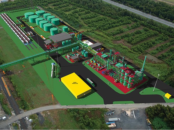
FIGURE 4. This site layout model, produced using CADWorx from Intergraph, shows piped, road and rail links
The size of the site is determined from the area of individual plants, storage areas and central buildings plus the clearances between the plants. It is also necessary to allow ample space for things like parking, loading and unloading, stores and firefighting water storage. Typical clearances, size and areas are given in Ref. 12. During the development of this layout, allowance must be made for future plant expansion and for general construction and other access considerations.
It is essential to establish, within the overall layout, all the important positional relationships between elements of the layout that must be maintained. This consideration is crucial because available sites may not conform in shape or topography to the preliminary layout and some compromises and amendments to the layout are almost certain to be needed. In light of this, it must be known which relationships can be relaxed to fit the plant in the available space.
Simple drawings and paper cutouts are very useful for site-layout development. Physical and 3-D computer models may also be used especially to gauge the visual impact.
Step 12. Hazard assessment of site layout. The plots on the site where loss of containment can possibly occur are noted. Vulnerable parts of the site are listed, such as offices, central utilities, key commercial plants and the site boundary (representing the start of the public domain).
The consequences of each loss through fire, explosion or toxicity on the vulnerable items are calculated. The layout is adjusted so that the consequences become acceptable; in particular, the chance of escalation of an occurrence throughout the site (via the “domino effect”) is made less likely. Ref. 12 goes into further detail on this topic.
Step 13. Site-layout optimization. When there are feasible alternative arrangements, cost estimations should be developed for each with respect to transport and piping connections between the various plots and so on. The most economical layout can then be subject to further optimization of the plot spacings, subject to the hazard constraints.
Step 14. Critical examination of site layout.The proposed site plan should ideally be examined critically by the various disciplines first separately and then together. Points to review include the following:
- Containment of hazards and safety of employees and public
- Emergencies
- Transport and piping systems
- Access for construction and maintenance
- Environmental impact, including drift of airborne effluents and discharge of liquid effluents
- Future expansion
Additional points are included in the checklist in Ref. 12. In the worst case, it may become obvious during the review that one or more of the proposed plants is unacceptable, but in most cases, the review will result in adjustments to the site layout, iterating from Step 11 onward.
Step 15. Site selection.The results of site layout will be:
These factors, plus the others outlined in Ref. 12, will guide the selection of a suitable site.
Detailed site layout
Step 16. Site data. No site will be ideal, however much care is taken in its selection. So after site purchase, the engineer has to adjust the layout to the constraints of the site and it is important that these are clearly established. They could include:
- The load-bearing ability of the soil and subsurface conditions
- Site grading and drainage features
- Extremes of weather, which may make it desirable to provide special shelter or protection for equipment or operators
- Prevailing wind direction for consideration when locating intake or exhaust stacks, or furnaces up- or downwind in relation to the remainder of the plant. Also sand, sea-spray and leaves can be blown by the wind onto a plant
The following items should be based on the owner’s and national standards and codes of practice:
- Road width, radii and gradients
- Service corridors
- Pipe-bridge heights over roads, railways and pipe-trenches
- Building lines
- Architectural finish to buildings
It is likely that while the site is being selected and purchased, further process and engineering design and market research work has been undertaken on the individual plants and their products. The plot layouts could have been updated and the further information, relevant to the site layout, made available.
Site 17. Site layout. Steps 11–14 should be repeated, but in greater detail and subject to the constraints of the selected site. Possible layout changes to the original plan could be caused by the following:
- The desirability of placing a heavy plant on good load-bearing soil
- The position of road, rail and service access points
- The need to put hazardous plants away from public places, such as schools, and to take note of neighboring hazards
- The desirability to have a good environmental impact (as described in Section 3.8 of Ref. 12)
- Planning restrictions
The hazard assessment can now take account of known vulnerable features outside the site boundary. The critical examination will, in addition to the items given in Step 14, also check that site constraints and standards have not been violated. Extensive consultation will be made with the various regulatory and emergency authorities during the detailed layout stage.
The final site plan will show the roads, railways, site pipe routes, sewers, central buildings and services. It will ideally be produced in the form of, and with the aid of, detailed drawings and possibly models, whether computer,nmanual or both.
Detailed plot layout
Step 18. Plot layout data. The detailed plot layout information includes the following:
- Owner’s basic practices and standards
- National and international codes of practice, standards, specifications and regulations
- Contractor’s standards where the above are not available
- Location and relationship of roads and railways surrounding the plot and estimates of traffic that might interact with the plot’s loading and unloading facilities
- Steam, water, sewage disposal, and other services, particularly the terminal points relating to the plot
- Raw material and product pipeline terminals
- Sources of atmospheric pollution that might affect the process operators or maintenance staff
- P&IDs indicating (with identification codes) the process equipment and instrument requirements and showing the pipeline connections
- PFDs showing the flows and composition of each stream
- Line schedules giving each pipe its size, specification and the temperature and pressure conditions
- Equipment schedules and drawings providing the specification of each item together with its plant size, register number, critical dimensions, process power requirements, process and utility nozzle connections and flows, materials of construction, process conditions, operation and maintenance requirements
- Process design datasheets containing the process design data, philosophy and calculations and indicating any process layout requirements
- The results of the hazard and operability studies of the process design
- The drawing conceived in Steps 1–9
Step 19. Plot layout. Most of the initial steps, particularly Step 4, and 6–9 are repeated in greater detail and subjected to the site constraints given in Step 18.
It is important that, in repeating Step 6, there is good coordination between the layout, process, operating, piping, civil, structural and mechanical disciplines. The piping arrangement studies (repeat of Step 8) done here are discussed in more detail in Ref. 12.
The hazard reassessment (Step 9) will be mainly concerned with internal plant spacings, such as area hazard classification zones and control room and other plant building positions. Inter-plot spacings are considered in hazard assessment of the site layout. The repeat of the critical examination should (as well as considering the aspects given in Step 9) also see that standards, regulations and site constraints on the plot have not been violated.
Hazard assessment
Increasingly, regulatory authorities will require a combined hazard assessment of the site and plot layouts after both have been tentatively finalized. Some existing activities will be required to submit hazard assessments. These include the following:
- Interactions between items within the plot
- Interactions between plots within the site
- Interactions between the site and its surroundings
The approach discussed here is a formalized summary of the steps that are typically taken by chemical engineers on large or dangerous plants. Less formal approaches are more commonly used in practice, however, for reasons of economy and practicality. Critical examination in particular is a resource-hungry exercise.
Author
 Seán Moran is managing director of Expertise Ltd. (25 Warmbrook, Wirksworth Derbyshire, U.K.; Email: [email protected]; Phone: +44-1629-826482). He holds a Masters Degree in Biochemical Engineering from University College London, and is a fellow of the Institution of Chemical Engineers. Moran has 25 years of experience as a process plant designer, commissioning engineer and troubleshooter. He has published two books [12,16], and is presently working on another book, entitled “An Applied Guide to Water and Effluent Treatment Plant Design.”
References
1. Kern, R., Arrangements of process and storage vessels, Chem. Eng., 84, 93, 1977.
2. Kern, R., How to manage plant design to obtain minimum cost, Chem. Eng., 84, 130, 1977.
3. Kern, R., How to get the best process plant layouts for pumps and compressors, Chem. Eng., 84, 131, 1977.
4. Kern, R., Layout arrangements for distillation columns, Chem. Eng., 84, 153, 1977.
5. Kern, R., How to find the optimum layout for heat exchangers, Chem. Eng., 84, 169, 1977.
6. Kern, R., Space requirements and layout for process furnaces, Chem. Eng., 85, 117, 1978.
7. Kern, R. Arranging the housed chemical process plant, Chem. Eng., 85, 123, 1978.
8. Kern, R., Instrument arrangements for ease of maintenance and convenient operation. Chem. Eng., 85, 127, 1978.
9. Kern, R., Controlling the cost factors in plant design. Chem. Eng., 85, 141, 1978.
10. Kern, R., How to arrange the plot plan for process plants, Chem. Eng., 85, 191, 1978.
11. Green, D.W., and Perry, R.H., “Perry’s Chemical Engineering (8th Ed.).” New York: McGraw-Hill, 2007.
12. Moran, Sean, “Process Plant Layout, 2nd Ed.” Institution of Chemical Engineers, Butterworth-Heinemann, 2016.
13. Kidam, K., and Hurme, M., Design as a contributor to chemical process accidents, Journal of Loss Prevention in the Process Industries, 25, 2012, pp. 655–666.
14. Mecklenburgh, J.C.,”Process Plant Layout,” Halsted Press, 1985.
15. The Mond Index, GDG Associates, 1985.
16. Moran, Sean, “An Applied Guide to Process and Plant Design,” Butterworth-Heinemann. 2015.