Closing off pressure upstream can minimize the need for pressure-relief systems to open, avoiding product waste and possible environmental damage
Any system within a chemical process industries (CPI) manufacturing plant that is pressurized, or could experience pressure during an upset or malfunction, must have a pressure-relief mechanism. This helps alleviate a situation where pressure capable of bursting vessels or piping develops. The first approach for protection is a mechanical device designed to open at a specific pressure to release the contents. Typical examples are pressure-relief valves (PRVs) or rupture disks. These open and allow the contents to escape to the atmosphere, a flare manifold or a collection system.
The problem with this approach is the amount of product lost, along with the potential for an environmental incident if the contents are not fully captured and treated appropriately. For example, a plant’s flare system must have the capacity to handle large releases, which could require a more robust system than is needed on a routine basis. In other words, an overpressure incident involving product release through a mechanical pressure-relief system is expensive not only in lost product and potential environmental incidents, but also in the equipment necessary to handle the release. This can be made all the worse by a large process supply, such as that found in a pipeline. Without being shut off, the flow out of an opened PRV from a pipeline could be virtually inexhaustible.
In some situations, it may be more practical to change the approach from releasing the pressure to cutting it off upstream at the source as quickly as possible to minimize or prevent product release through a PRV. Although this seems like an obvious solution, it happens less than one would expect; product is still lost with all the associated costs and inconveniences. It is important to consider alternate solutions to address safety and production challenges.
Relieving at the source
As a typical example, an overpressure protection system (OPS) (Figure 1) can be used to protect a reactor by shutting off the pressure source where it reaches the critical vessel. One approach shuts down the system when it reaches 116% of the rated pressure, and before the PRV is set to open. This is a basic safety instrumented function (SIF) and should be part of the larger safety instrumented system (SIS) protecting the process unit or larger plant.
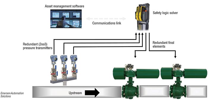
Figure 1. The OPS is installed on a main line supplying a process unit. If the feed pressure passes a critical threshold, it shuts off the feed prior to the PRV opening
If designed and applied properly, the OPS may be able to mitigate the need for an additional pressure-relief system. This is particularly critical when the pressures involved make a PRV impractical, or the systems designed to handle a product release might be inadequate for the potential volume. Such situations can emerge when a plant is changed to increase production or a process unit is modified. The capital expenditure costs of enlarging a flare system can be much higher than adding an OPS.
There are situations where an OPS cannot be used to replace a conventional pressure-relief system, such as compressed air or steam. In such situations, it becomes necessary to have the two systems work together, with the PRV serving as a backup.
The design and implementation of an OPS must be approached just like any other SIF following the procedures outlined under the International Electrotechnical Commission’s (IEC) 61511 standard (ISA-84). If this standard is not familiar, there are many resources available covering the topic in far greater depth. IEC 61511 provides a complete safety lifecycle approach, covering everything from conceptual process design with hazard analysis and risk assessment, all the way to operation, evaluation and management of change. Any OPS should be evaluated and designed by experts with competency in safety standards and process design within this framework. For purposes of this discussion, we will concentrate on the middle steps of the process covering detailed design and installation, but all the other elements need to be included.
Looking at the individual parts
Returning to the earlier example, let’s focus on the OPS function itself. It is a basic SIF designed to shut down flow in the event of an excessive pressure incident. Since it is a SIF, it has three basic parts: a sensor, a logic solver and a final element. These can be simple or highly sophisticated, but any components used must be certified to operate in a SIS context, with any uncertified components justified as proven-in-use.
A SIF must be able to perform its function independently without depending on any larger automation system, or even plant utilities. Should there be larger failures in the unit, it must be able to shut off the flow at least once and remain closed. A bare-bones system could use a pressure switch connected to a simple logic solver and a shut-off valve designed to fail closed in the event of a loss of electric power or compressed air. This can probably do the job, but will be difficult to test, will not provide any diagnostic information, and won’t have any capability to minimize false trips. One shutdown caused by a false trip or pressure switch failure will likely cost more than installing a more sophisticated system.
Implementing an improved OPS
The same sophisticated technologies that make instrumentation smart and control systems more effective can also apply to SIFs. Let’s look at how they might be applied in this situation.
The sensor can be a pressure transmitter (Figure 2), which is safety-certified and able to provide diagnostic information in addition to a basic pressure measurement. A pressure transmitter with advanced capabilities can evaluate the complete measurement system, extending diagnostics to capture over-pressure scenarios and improve reaction time. Speed is critical because the OPS must respond immediately to initiate the pressure protection system and protect the downstream equipment.
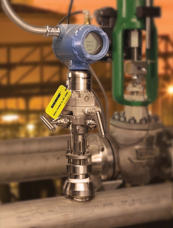
Figure 2. Safety-certified smart pressure transmitters have internal capabilities to perform continuous loop diagnostics to spot problems such as clogged impulse lines Emerson Automation Solutions
Advanced transmitter capabilities can include functions such as plugged impulse-line detection, which can be communicated to the logic solver via a wired or wireless digital communications protocol. This valuable information can be passed on to the larger process-control and maintenance systems without interfering with the basic safety function.
While one transmitter may be sufficient to provide the safety function, highly critical systems where shutdowns are exceptionally costly may call for three pressure transmitters arranged in a two-out-of-three (2oo3) voting scheme to reduce the potential for a false alarm caused by a transmitter malfunction. Using this approach, at least two transmitters must report an overpressure incident to trip the system and cause a valve closure. This also provides a backup if one or even two transmitters are damaged or malfunction.
We’ll come back to the logic solver in a moment, but let’s first look at the final element. The ultimate purpose of an OPS is to close a valve to cut off the source of pressure. It may be a single valve, but as the diagram shows, it may also be two valves in series so that either one can close and isolate the process. Having two valves eliminates a valve malfunction as a single point of failure.
Valves in this service should be safety-certified, and must fail closed (Figure 3). If there is a loss of any or all plant utilities, such as compressed air to a valve, or if communication is cut off to the logic solver, the valve must close itself and stay shut. To handle these and other similar situations, fail-closed valves are typically spring loaded and have to be held open by the instrument supply medium, such as compressed air. But as mechanical devices, a potential failure mode is becoming stuck in one position, leaving them unable to do their job when called upon.
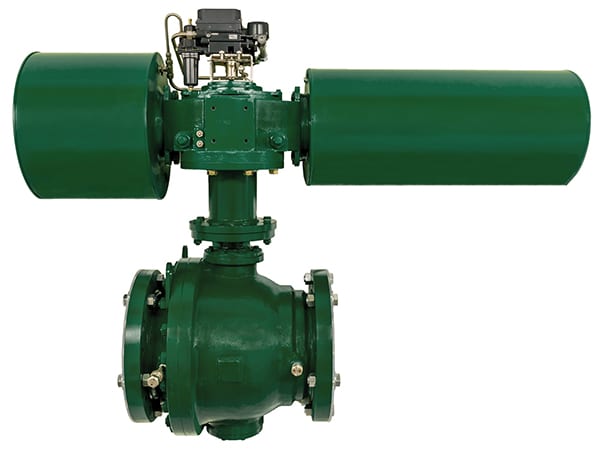
Figure 3. This 12-in. valve is typical of a shut-down valve for OPS service. It is a trunnion-mounted ball valve assembly with a scotch yoke pneumatic spring return actuator and digital valve controller Emerson Automation Solutions
This is particularly important for SIFs, since these valves don’t normally change position very often. Fortunately, the actuators that move these valves can include a smart digital valve controller (DVC). It can perform self-diagnostics and determine if corrosion or some other condition is causing a valve to require more force to move and can detect when there is a change in the compressed air supply, power quality or whatever other motive force they may depend upon. The DVC performs operations that can assist with proof testing as well as partial-stroke tests, gathering and evaluating performance data. Proof and partial-stroke tests are important periodic tests that confirm operability in accordance with IEC 61511. Data gathered can be passed to the logic solver as well as asset management tools, which can also be utilized by operations and maintenance personnel to make predictive maintenance decisions.
Depending on the nature of the process, the valves used with an OPS can be quite large, yet they must close quickly and positively in a controlled manner. Large actuators sometimes need to be powered by hydraulic systems to have sufficient force to close. Even large valves must have actuators including stored energy systems, enabling them to fail closed. If driven by stored hydraulic pressure, this pressure must be monitored to ensure it is available when called upon.
The logic solver ties together the OPS. In the most basic form, it might be little more than a glorified relay, responding to a binary switching signal from a digital sensor and telling its valve to close, but it can also provide insight into the safety function, and even the process, if provided with the sophisticated functionality available today.
A smart logic solver has the capability to work with three pressure transmitters in a 2oo3 voting scheme, and it can tell if a transmitter is malfunctioning by reading the diagnostic information. It monitors all functions continuously, and if there is a problem, it can compensate while warning operators of the situation. The same applies to valve actuators, since they can receive, interpret and act upon diagnostic information from smart transmitters and actuators.
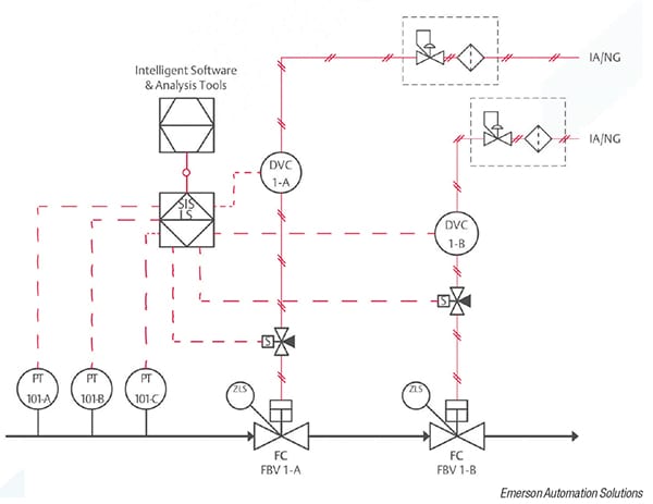
Figure 4. This typical OPS monitors the feed to a reactor or other part of a process unit for high pressure
Putting it all together
A typical system could use three pressure transmitters, each sending measurement and diagnostic data to a logic solver (Figure 4). Using a 2oo3 voting scheme, the system will trip if line pressure exceeds the setpoint and it is detected by at least two of the transmitters. The shutoff valves close by spring actuation and are held open by a regulated compressed-air supply.
If the system trips or there is a larger failure in the unit, the solenoid valve or digital valve controller cuts off the compressed-air supply and dumps it from the actuators, causing the valves to close. The DVCs monitor air-line pressure and valve function. They can also perform partial-stroke valve tests automatically to determine if the valve condition is changing. All of this is monitored by the logic solver using analysis tools, which can warn operators and maintenance personnel if there are any changes in equipment or performance.
Creating an effective OPS requires selecting and integrating the right components following analysis in accordance with IEC 61511. Once designed, it must be evaluated as a system, usually by a third-party, to ensure it can perform as expected under the appropriate SIL requirements. It can be installed with less process downtime compared to the cost and complexity of a flare system expansion project. An OPS provides a variety of cost benefits, including the following:
- Reduces or eliminates the need for resizing the flare or relief manifold
- Reduced process downtime
- Reduced number of flaring events and volume released
- Reduced manual system testing
As environmental regulations continue to become more stringent and the ability to keep qualified operators grows more difficult, these systems will be increasingly considered for both operational and financial reasons.
Authors
 Erik Mathiason is a global pressure product manager for Emerson Automation Solutions (6201 Innovation Blvd., Shakopee, MN 55379. Phone: 952-204-4436. Email: [email protected]). He is responsible for Rosemount Pressure Transmitters. He has worked in various roles within Emerson, primarily focusing on pressure and pressure SIS solutions. He has a B.S. in mechanical engineering from North Dakota State University and an M.B.A. from the University of Minnesota, Carlson School of Management.
 Afton Coleman is the senior marketing manager at Emerson Automation Solutions (205 S. Center Street, Marshalltown, IA 50158. Phone 641-751-3439. Email: [email protected]). She is responsible for Fisher Digital Isolation Solutions used in safety instrumented systems. She has worked with Emerson since 2005 and is a Certified Functional Safety Professional (CFSP). She has a B.S.E. in chemical engineering from the University of Iowa and an M.B.A. from Iowa State University, Ivy College of Business.