Targeted use of blanketing with inert gas offers an effective strategy for preventing combustible dust explosions in CPI facilities
Combustible dust is a critical safety concern for the chemical process industries (CPI). The use of nitrogen gas as an inert blanket offers an effective approach to preventing combustible dust explosions by displacing the oxidant required for an explosion. Nitrogen inerting is a practical solution to help prevent the devastation to personnel and property that can result from combustible dust explosions. Moreover, while nitrogen is not the right solution for every system, when properly designed and installed, it is often safer, less expensive and easier to maintain than alternative mechanical solutions. Using a set of examples, this article explores how nitrogen can be used to prevent — not just mitigate — combustible dust explosions in CPI facilities.
Regulations expand dust hazard scope
In December 2015, the Occupational Safety & Health Administration (OSHA; Washington, D.C.; www.osha.gov) will begin fully enforcing its new Hazard Communication (HazCom) standard, which adopts the Globally Harmonized System for the Labeling and Classification of Chemicals (GHS). Originally announced in 2012, the standard impacts a wide cross-section of industry sectors. One of the most significant changes in the new standard involves combustible dust. With the new HazCom standard, manufacturers will need to include combustible dust hazards in HazCom labeling, as well as in hazard evaluation and planning [1].
As a result, many chemicals not previously classified as hazardous will be officially designated as combustible dust hazards and will require adherence to NFPA 654, the combustible-dust explosion protection standard of the National Fire Protection Association (Quincy, Mass.; www.nfpa.org). While housekeeping and dust mitigation are recommended as a primary step to prevent combustible dust explosions, NFPA 654 also recommends explosion-mitigation devices to control explosions and limit damage. For example, the standard recommends including blowout panels in baghouses to release pressure from an explosion, or inline suppression systems to quickly extinguish an explosion or fire. However, these recommendations still leave the process fundamentally unsafe by only dealing with the explosion rather than preventing it. A safer way to comply with NFPA 654 is to use targeted nitrogen inerting rather than mechanical relief and suppression devices in selected areas.
Combustible dust fundamentals
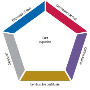
While a triangle of required ingredients determines whether or not a fire can be sustained, combustible dust explosions are governed by a pentagon of interacting factors: oxygen, fuel, containment, ignition and dust dispersion (Figure 1). If one side of the pentagon is eliminated, an explosion is not possible.
Most materials can explode under the right conditions. In fact, it is easier to identify the materials that will not combust. OSHA’s National Emphasis Program (NEP) on combustible dust defines the term as, “A combustible particulate solid that presents a fire or deflagration hazard when suspended in air or some other oxidizing medium over a range of concentrations, regardless of particle size or shape.”
Defining which particulate matter presents a deflagration hazard requires specific laboratory analyses of several properties that are essential to determine the severity of a combustible dust hazard for a given material. These properties include, at a minimum, the limiting oxygen for combustion (LOC), minimum ignition energy (MIE), minimum ignition temperature (MIT), and the layer ignition temperature (LIT). Specialized laboratories can conduct these material characterizations and offer analysis of the resulting hazard.
Several parameters define a material’s properties with regard to its combustibility. In terms of particle size, 425µm (40 mesh) is generally defined as the limiting size to classify a material as a “dust,” although certain materials with high surface area (such as fibers) may be combustible above that size threshold. A material’s Kst (dust deflagration index) provides an indication of the severity of a dust explosion hazard. NFPA classifies dusts by Kst value. A dust is only considered inert with a Kst value of 0. Class 1 dusts are rated below 200 Kst, Class 2 dusts range from 200 to 300 Kst, and Class 3 dusts are rated above 300 Kst.
The minimum explosive concentration (MEC) is the limiting dust concentration to create an explosive atmosphere. The MIE and MIT are values used to define explosive conditions for particular materials. Table 1 contains the applicable dust properties of some common materials.
 Following laboratory analysis, manufacturers will be able to determine the severity of the combustible dust hazard and document whether, in fact, the dust is not combustible. However, the majority of dusts are combustible, so most manufacturers will use these properties not to define whether the dust is combustible, but rather to define the severity of the hazard.
Several high-profile accidents have recently raised the awareness of this hazard in the manufacturing industry. For example, in 2008, 14 people were killed and 44 people were injured at one of the largest industrial incidents at the Imperial Sugar factory in Port Wentworth, Ga. Sugar dust that had built up to explosive concentrations in the factory ignited, sending a fireball cascading through the building. Many dust explosions have occurred with seemingly innocuous materials, such as organic compounds like sugar.
Following the Imperial accident, OSHA began focusing on the dangers of combustible dust explosions. In 2008, OSHA launched its NEP on combustible dust. Using the General Industry Standard 29 CFR 1910, Section 5(a)(i) of the Occupational Health and Safety Act (commonly known as the “general duty clause” [2]), along with generally accepted good practices, such as NFPA 654, OSHA began conducting extensive inspections in facilities containing dust.
In 2009 alone, 1,000 inspections were completed, and over 4,900 violations were issued for non-compliance, including poor housekeeping, inadequate hazard communication, and inadequate hazard control [3].
To date, most of the regulatory and industry focus in designing systems to handle combustible dust has addressed either the dust itself (through housekeeping initiatives), or the confinement of explosions. For explosion confinement, systems are designed so that energy can be released in a controlled manner. Examples of this type of control include blowout panels on silos or overdesigning ducting to withstand the force of an explosion. However, such measures focus on mitigation — the explosion still occurs. One of the safety infractions commonly cited by OSHA combustible dust inspectors are knock-out panel reliefs that vent to areas where employees are working. In such cases, the severity of the explosion may be mitigated, yet the risks of personnel injury still remain.
The case for inert gas for dust
Gas inerting represents an alternative approach, and works by disrupting the oxidant side of the dust-explosion pentagon. Insufficient oxygen means no combustion. Note, however, that there are some chemicals, such as peroxides, that contain bound oxygen and could still present a fire of explosion hazard in the absence of oxygen gas. For those chemicals, additional safety steps, including close control of temperature, are required.
The CPI has been using inerting to eliminate fires from flammable materials for years. Fires require the presence of oxidant, fuel and heat (the fire triangle). For every chemical, there is a minimum level of oxygen required for combustion, called the minimum oxygen concentration (MOC), measured in percent oxygen. For decades, chemical manufacturers have been mitigating their fire risks from flammable materials by blanketing tanks and reaction vessels with nitrogen to reduce the oxygen content below the MOC. A similar methodology can be transferred to combustible dust explosions, where the inert-gas approach has not been typically applied.
The reasons for industry resistance to inerting boil down to three main perceived issues: nitrogen cost, safety and practicality. In reality, the perceived disadvantages can be easily overcome.
Cost. The cost of inert gas can be reduced in several ways. Depending on the application, inert gas use may be targeted to selected units or processes. Alternatively, the MOCs of many combustible dusts do not require 99.99% pure industrial grade nitrogen from a liquid nitrogen source. By using lower-purity nitrogen — such as 95 or 98% pure nitrogen, such as that generated by a membrane or pressure swing adsorption (PSA) system — total nitrogen operating costs can be reduced. NPFA 69 and 654 provide guidance on determining the MOC for a combustible dust and the required nitrogen purity for safe inerting.
Safety. Asphyxiation risks are managed with basic safety training and simple engineering controls, such as O2 monitoring and O2-concentration control, as well as restricting inerting to appropriate areas.
Practicality. Maintenance on the nitrogen system is typically handled by the nitrogen provider and not by the end user. Nitrogen systems are in fact not all that maintenance-intensive, and unlike explosion detectors they do not require quarterly inspections.
Potential dust-related applications of nitrogen inerting include closed-loop pneumatic conveying, hopper storage, shredders, reactors, tanks, vessels and enclosures. Through smart design, inerting systems can eliminate the possibility of an explosion, increase worker safety, and provide a more cost-effective solution relative to other mechanical-protection systems.
Example 1. Plastic powder
Plastic powder coatings require a very fine powder to ensure a smooth coating when applied. The powders are created by pneumatically conveying plastic pellets into a mill for fine grinding. Particle sizes less than 100µm (140 mesh) are frequently required for coating production.
Polyethylene (PE) is the most common plastic used in powder coating manufacturing, but polyvinylchloride, polyester and polyurethane compounds are also common. At particle sizes less than 100µm (140 mesh), these plastics are highly combustible. In fact, PE powder is among the most common fuels for combustible-dust explosions because of its broad usage and its combustibility.
For example, fugitive PE dust caused an explosion at the West Pharmaceutical plant in Kinston, N.C., in 2003. According to the Proceedings of the 5th International Seminar on Fire and Explosion Hazards, the PE was used in a slurry to coat rubber parts, and fugitive PE dust from dried slurries accumulated in the suspended ceilings and cooling air ducts. A spark from a mill motor caused the dust to ignite, sending a flame propagating through the ducting. The ducting then over-pressurized, sending the explosion front and burned dust into the suspended ceiling, which caused a larger explosion from the dust that had settled in the ceiling.
This case is particularly noteworthy because there was no previous accumulation of dust in the facility, due to top-class housekeeping practices. The facility had recently upgraded its dust-collection system and believed that the dust in the ceilings was inert based on previous laboratory testing. Indeed, investigative testing of the dust in the dust collectors indicated a largely inert dust. However, based on investigations following the explosion, only 280 lb of PE was required to produce the magnitude of the explosion felt during the incident. For a 10,000-ft2 ceiling, that amounts to a layer of PE dust with a thickness of only 0.013 in. — about the thickness of four sheets of copy paper [4].
The explosion and subsequent fire resulted in six fatalities and multiple injuries. In the case of West Pharmaceutical, while it would be difficult to inert the ceiling ducting, it is quite possible that the mill itself could have been inerted, preventing the initial reaction. Either way, the incident highlights the significant danger of PE powder.
Economic analysis
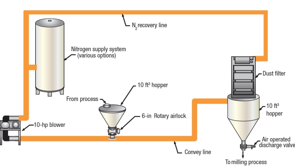
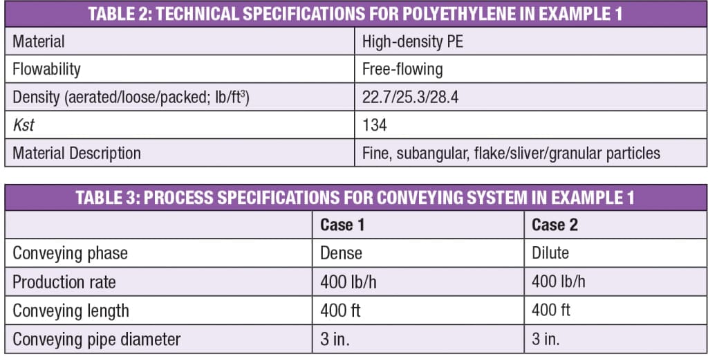
One of the main misconceptions about nitrogen inerting is that it is much more expensive than traditional mechanical explosion-protection systems. In reality, on a total net-present-value (NPV) basis, nitrogen inerting systems are very comparable to reactionary mechanical systems and, in the case of even a small incident requiring cleanup with a mechanical system, the nitrogen inerting system is often more economical. The following example illustrates how the economics could work. Consider a pneumatic conveying and milling system for PE-powder-coating manufacturing. Figures 2 and 3 show the two cases that were developed. In Figure 2, the system is protected using traditional mechanical combustible-dust protection systems, including explosion detection devices, suppression systems and blowout panels. Figure 3 depicts the system as protected by nitrogen inerting. Table 2 shows the technical specifications for the PE that was used in the case study models.
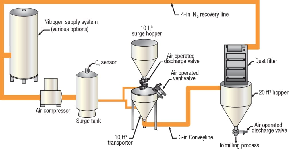
Figure 2. The pneumatic conveying system depicted here is equipped with traditional mechanical protection systems for combustible dust, including explosion-detection systems and blowout panels
Both dilute and dense phase conveying conditions were modeled in the case study. Table 3 shows the process specifications for the cases that were modeled.
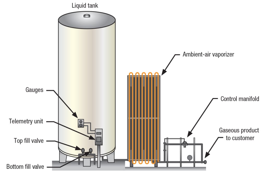
The nitrogen-protected system relies on the pressure of the nitrogen bulk tank to drive the pneumatic conveying process. A typical liquid-nitrogen bulk system can deliver gaseous nitrogen to house lines at pressures up to 200 psi without auxiliary compression. The vaporized gas is fed directly into the pneumatic conveying system. Figure 4 shows a typical liquid-nitrogen-supply system layout. The supply tank ranges in size from 60 gal to upwards of 11,000 gal to fit a wide variety of system needs.
To make efficient use of the nitrogen, a gas recovery unit was included in the system design. The gas recovery unit can recycle about 80% of the nitrogen used in conveying, drastically reducing the nitrogen consumption.
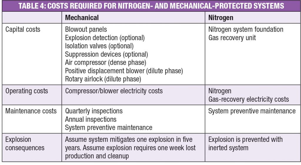
The mechanically protected system includes blowout panels for explosion protection. Please note that this is a basic explosion-protection system design, assuming an ideal plant layout for blowout panels. Depending on the working environment, system layout, and other safety considerations, additional explosion detection or suppression devices may be needed. The estimate includes one explosion incident in a five-year period requiring one week of downtime and cleanup. The incident-related costs include the time for lost production and related cleanup and replacement costs.
Tables 4 and 5 summarize the scope differences between the cases. The costs for each case are based on actual quotations for capital and maintenance, and current national U.S. averages for nitrogen and electric costs. An interest rate of 6% was assumed for the NPV calculation.
When comparing the estimated cost differences between these four scenarios, several observations can be made. First, for both the nitrogen-protected and mechanically protected dilute-phase systems, the capital costs are higher than the respective capital costs for the dense-phase systems. When looking at the mechanical protection case, the dilute conveying case requires a higher volume of air for the conveying medium. More air leads to higher severity in the event of an explosion, therefore requiring more robust explosion-prevention capital. When looking at the nitrogen protection case, the combination of the positive-displacement blower and airlock required for dilute-phase conveying is a higher cost than that of the gas-recovery compressor needed on the nitrogen dense-phase system.
Second, operating costs for the dilute-phase nitrogen system are higher due to the higher volume of nitrogen needed for the dilute-phase system. In this case, the dense-phase system concept requires less than 10% of the average air or nitrogen usage than the dilute-phase system concept.
Third, maintenance costs for the mechanical-protection systems are higher than those for the nitrogen-protection systems, mainly due to the costs of annual inspections required by the explosion-protection devices.
Finally, looking at the dense-phase conveying scenario and considering the costs from a small incident occurring once in five years, the nitrogen system is cheaper on a five-year, NPV basis. Because of the high gas flowrates required, the nitrogen system for the dilute-phase pneumatic conveying system is more expensive on a five-year, NPV basis.
However, beyond a simple NPV calculation, this exercise does not take into account all factors that should be considered when designing a dilute-phase pneumatic conveying system. For example, plant layout is an important consideration. Due to location in the plant, a system retrofit design would require much more explosion protection than a system that could be placed in an ideal location. Vents for explosion panels may require long ducting lines or secondary protection systems to prevent employee injury — a practice discouraged by NFPA 68 because shorter ducts decrease explosion severity. In certain retrofit cases, mechanical explosion protection can leave manufacturers with a difficult challenge in trying to meet code requirements safely.
Each incident will be specific to a manufacturer’s particular product and protection system, so the cost and frequency of an incident occurring may vary. However, even small incidents may require plant downtime, replacement of protection systems, and cleanup of hazardous material. A nitrogen system greatly decreases the risk of any explosion happening at all, as well as any related expenses. In this case, an NPV difference of $100,000 is minimal in comparison to the total capital of a pneumatic system and the significantly reduced explosion risk that comes with an inherently safe inert system over the course of the system’s life.
Example 2. Tire manufacturing
One industry that will be heavily impacted by the adoption of the GHS is the tire manufacturing industry. Under the new regulations, carbon black, a material used extensively in tire production, will be classified as a combustible dust. This will require tire manufacturers to review their existing processing plants and retrofit them to comply with NFPA regulations, potentially requiring expensive capital investments if traditional suppression controls are utilized.
However, tire manufacturing is an application that lends itself to nitrogen inerting because nitrogen is often already used in the tire curing process at many plants, where it is injected into the tire molds to cure the tires. Because the nitrogen is already onsite, it can easily be incorporated into a dust-control scheme using inerting without incurring additional installation costs. In addition, since the nitrogen used for curing can be recycled through the pneumatic lines, the nitrogen needed for curing easily supplies the need for inerting. This simple system removes the need to install mechanical retrofits to comply with NFPA 654. This system has been installed at large tire producers specifically to combat the dust hazards identified with the new classification of carbon black dust.
Example 3. Grain manufacturing
The food industry may be the most impacted with the new changes. Some of the most highly combustible dusts are found in the food manufacturing industry, with sugar and grain being two of the more notorious culprits. It is estimated that 150 people have died in food-related combustible-dust explosions in the last 20 years in the U.S.
Some components of a food processing plant are impractical to inert, such as grain elevators, but there are many contained areas that can be inerted safely and economically. Selective inerting as part of a combustible dust plan can reduce the cost of overall protection. Hoppers are a great example of how smart design can make nitrogen inerting possible.
The authors were involved with a recently designed and installed nitrogen-inerting system in a large biomass hopper with the aid of computation fluid dynamic (CFD) modeling. The CFD models provided precise estimates of the methane offgas concentration levels throughout the silo and guided the placement and orientation of nitrogen-injection nozzles throughout the silo (Figure 5). Rather than flood the silo with nitrogen, the hopper owner was able to apply nitrogen in locations and amounts that exactly matched what was required to prevent a dust explosion within a large space.
The same process could be used for smaller silos and hoppers in the food processing industry, as well as other storage containers. Closed-loop pneumatic conveying lines are another prime target for incorporating nitrogen inerting.
Beyond economics
Beyond the economics, there are several other qualitative differences between mechanical explosion mitigation and nitrogen inerting systems that should be considered. First, from a safety perspective, the nitrogen system creates an inherently safe environment with regard to explosion protection, while the mechanical system reacts to the explosion. In the mechanical system, there are several modes of failure for the system, and components like blowout panels are difficult to test in order to confirm functionality. Further, testing suppression devices and explosion detection systems require a system shutdown. In contrast, there is only one failure mechanism for the nitrogen system: loss of nitrogen. A pneumatic conveying system can be driven by the pressure from the nitrogen system, so the system automatically shuts down with a loss of nitrogen supply.
For manufacturers who do not currently use nitrogen in significant amounts, one of the major concerns is the potential risk of nitrogen asphyxiation. Already used widely in the CPI, nitrogen can be implemented safely as long as proper procedures for storage, handling and use are followed [5]. Nitrogen should never be vented into a location where workers are present or into a confined space that could be unintentionally created. In addition, oxygen monitors must be installed to alert workers in the event of an oxygen-deficient atmosphere.
Implementing N2 inerting
For manufacturers interested in implementing nitrogen inerting for dust safety, there are guidelines that can be followed.
Process design. Nitrogen inerting works best in certain enclosed or semi-enclosed areas, such as closed-loop pneumatic conveying systems, storage hoppers, vessels, dryers, spray dryers, grinding mills, granulators, shredders and mixers.
Nitrogen supply. Nitrogen requirements will vary greatly depending on the material being processed, production rate, process conditions, size of the vessels, number of use points, and MOC. All of the required flowrates can be supplied by a nitrogen system, but the mode of supply will depend on the average consumption, as well as on peak requirements and usage pattern. For example, at low flowrates, a microbulk system may provide the most cost-effective supply. For the highest flowrates, onsite nitrogen generation systems could be considered. In many cases, a nitrogen-recovery and recycling unit greatly improves the overall system economics to reduce nitrogen usage.
With any nitrogen system installation, an oxygen-sampling system needs to be installed to verify the atmospheric oxygen content. These systems must also be designed with adequate controls to ensure that the correct oxygen levels are maintained. Oxygen monitoring can also include built-in controls to provide protection for emergency inerting should the process conditions change.
Pneumatic conveying system. In general, a pneumatic conveying system should be considered in situations where there is limited footprint or flexibility. Pneumatic systems are much easier to install in an existing plant space because it is easy to route a small-diameter conveying pipe around existing equipment. Pneumatic systems are totally enclosed, resulting in excellent dust control, and they have few moving parts, which saves on plant maintenance costs.
In all cases, when considering whether to install a nitrogen-inerting system, it is important to understand your current process well, including the properties of the materials in your process and their associated combustible-dust hazards. With that knowledge in hand, nitrogen experts and pneumatic conveying experts can be a good resource in the design of a safe and economic nitrogen inerting system.
While there are many places where nitrogen systems can be designed practically, cost effectively, and safely, there are situations where nitrogen inerting does not work as well. For example, large dust collectors or ductwork are usually not conducive to nitrogen inerting because of high flowrates and large spaces. Similarly, bucket elevators are usually not practical for nitrogen inerting because of the large spaces, lack of containment, and worker presence. In such situations, diligent housekeeping is the key to reducing the risk posed by dust explosions.
OSHA’s adoption of the GHS will require manufacturers in the U.S. to comply with many aspects of NFPA 654 for materials not previously considered combustible dusts. Manufacturers can choose to implement systems that mitigate the damage caused by combustible dust explosions, or they can choose to prevent combustible dust explosions from occurring in the first place.
Edited by Scott Jenkins
References
1. OSHA memorandum, 12/23/2013, www.osha.gov/pls/oshaweb/
2. OSHA Combustible Dust Standard, www.osha.gov/dsg/combustibledust/standards.html.
3. OSHA Combustible Dust NEP Report, www.osha.gov/dep/combustible_dust_nep_rpt_102009.html.
4. Baker, Q., Kinston Dust Explosion, Proceedings of the 5th International Seminar on Fire and Explosion Hazards, Edinburgh, U.K., April 2007. www.see.ed.ac.uk/feh5.
5. Air Products, Use Nitrogen Safely, www.airproducts.com/~/media/downloads/article/U/en-use-nitrogen-safely-312-12-023.pdf.
Authors
 Bridget Nyland is an applications engineer at Air Products (7201 Hamilton Boulevard, Allentown, PA 18195-1501; Phone 415-766-1594; E-mail: nylandbe@airproducts.com). She manages the evaluation and installation of all industrial gases applications for the chemical, pharmaceutical, rubber and plastics industries in the West Coast. She received a B.S.Ch.E. from Villanova University in 2011, and is a member of AICHE, SWE, EWB and WIB.
Tom Lee is a research and development engineer at Nol-Tec Systems (425 Apollo Drive, Lino Lakes, MN 55014; Phone 651-203-2547; E-mail: TomLee@nol-tec.com). With 27 years of material handling experience, he manages all aspects of Nol-Tec’s test facility, from evaluating current designs to devising new equipment.
Mitch Lund is a technical services engineer at Nol-Tec Systems (same address as above; Phone 612-418-7108; E-mail: MitchLund@nol-tec.com). He received a B.S.Ch.E. from the University of Minnesota-Twin Cities in 2012 and is involved in the innovation and design of new products and technologies.
Michael Thiel is the technical services group manager at Nol-Tec Systems (same address; Phone 612-799-4573; E-mail: MichaelThiel@nol-tec.com). He received a B.S.Ch.E. from the University of Minnesota-Twin Cities in 2005 and has managed the Technical Services Group since 2012, leading product development and new technology efforts.
