Corrosion and deposition in boilers, steam turbines and many types of process equipment are among the most expensive causes of outages in utility and industrial steam plants. Deposits and scale buildup on heat-transfer surfaces reduce efficiency, and when allowed to accumulate on steam turbines, such buildup can reduce the capacity. Corrosion-related failures can result in outages ranging from a few days to several months, depending on the affected systems, and can potentially cost tens of millions of dollars.
To reduce the risk of corrosion and deposition in water and steam systems, the standard practice is to monitor cycle chemistry and control impurity levels within industry- and manufacturer-recommended limits for the equipment. In steam plants, the chemical parameters of interest include: pH; conductivity; sodium; calcium; magnesium; chloride; sulfate; fluoride; phosphate; acetate; formate; propionate; total organic carbon (TOC); silica; copper; and dissolved and suspended iron (oxides). Typical target concentrations are in the range of <1 part per billion (ppb) to several parts per million (ppm) [1, 2].
Unfortunately, many utility and industrial steam plants do not have properly designed and operated sampling systems to monitor water and steam chemistry. In fact, in water chemistry and corrosion control audits, sampling problems are found in roughly 70% of all plants. As a result, operating decisions are often based on data that can have sampling errors as high as ± 1,000%. These errors, as well as data inconsistencies and concentration swings in the analytical results, become commonplace and are often ignored by plant personnel, preventing the timely identification of actual chemistry excursions. This article outlines the principles that must be considered when designing and operating water- and steam-sampling systems.
Sampling system design
To monitor systems for the ingress of impurities and for the production and transport of corrosion products, several cycle streams are sampled and analyzed, either continuously or periodically. Proper design of the sampling systems is critical in order to produce samples and analytical results that are representative of the sampled stream [ 3–9]. Problems with sample withdrawal, transport, collection and handling are often major sources of errors that can lead to incorrect or unnecessary corrective actions by operators. A meticulously performed chemical analysis is of little value if a bad sample is used. As shown in the box on p. 43, there are many potential causes of sampling errors, some of which can cause analytical results to be orders of magnitude higher or lower than the actual concentration in the process stream.
In high-purity systems, the measured concentration of impurities in many of the process streams is in the low parts-per-billion (ppb) range. At such low concentrations, the fluid being extracted is very sensitive to any deposition or chemical reactions within the sampling system. The extraction of non-representative samples can lead to large sampling errors [3]. Even in lower-purity systems, sampling errors due to improperly designed sampling systems can be significant.
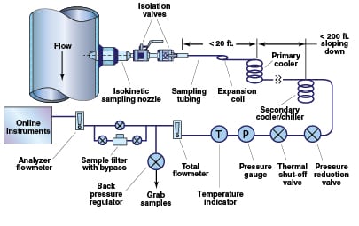
A well-designed sampling system (Figure 1) consists of an isokinetic sampling nozzle (discussed below), isolation valves, sample tubing, a primary cooler (for steam and high-temperature liquid samples), a secondary sample cooler, pressure-reduction and total-flow-regulation valves, a thermal-shutoff valve (for process temperatures above 100ºF), back-pressure regulator and sample drains.
Because steam impurities are easily adsorbed by magnetite (Fe3O4), the oxide buildup on the inner diameter of the sampling nozzle and tubing should be minimized. For this reason, all wetted components of the sampling system should be made from at least Type 316 stainless steel. Carbon and low-alloy steels should be avoided.
Deposit buildup in the sample lines can result in plugging of the sample line or seizing of sample isolation valves. Even when not directly affecting sample flow, deposits in the sampling system can affect the sample accuracy. Deposits can act as ion-exchange media and adsorb or release impurities during changes in the flow conditions. Even the best sampling-system design is still susceptible to deposition and plugging if the cycle chemistry at the plant is not maintained within industry standards, particularly when high concentrations of corrosion products (such as iron oxide or copper oxide) are present. Lengthy sample lines (for instance >100 ft) or low sample velocities (for instance < 4 ft/s) increase the probability of sample line blockage and can cause unacceptable time lags between sample collection and analysis. A sample flowing at 2 ft/s through 500 ft of tubing will take over four minutes to reach the analyzers.
Why isokinetic sampling?
Isokinetic sampling is the extraction of a representative portion of the process stream without altering the physical and chemical properties of the sample. In isokinetic sampling, all phases (solid oxides and precipitates, liquid droplets and vapor) of the sampled fluid enter the sampling nozzle with the same velocity vector (meaning the same velocity and direction of flow). The main reason isokinetic sampling is necessary is that the sampled stream is almost always a two-phase fluid (gas-liquid, gas-solid, liquid-solid) and the second phase typically has a very different chemistry composition than the steam or water [ 2]. In addition, the second phase (droplets or particles) typically has a different density and inertia compared to the primary phase (gas or liquid) and therefore would not be proportionally represented in a sample that was not withdrawn isokinetically. The benefits of isokinetic sampling have been verified during an Electric Power Research Inst. (EPRI) project [3] and through an independent analysis [10].
Sampling nozzle design
 |
|
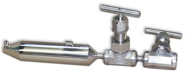
FIGURE 2. This weld-in style, single-port isokinetic sampling nozzle meets current ASTM
standards for sampling water and steam. Flanged connections to the process pipe are also acceptable (Source: Jonas) |
 |
|
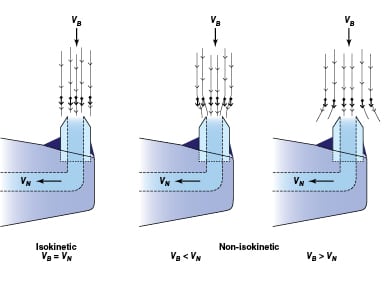
FIGURE 3. Shown here is the ideal flow path of particulate matter and droplets into isokinetic and
non-isokinetic sampling nozzles. In isokinetic sampling, the extracted fluid is representative of the composition in the process pipe, including particles and droplets. When the sampling is non-isokinetic, the concentration of particles and droplets can be higher or lower than that found in the process fluid. VB = velocity of process fluid; VN = velocity in the sampling nozzle (Source: Jonas)
|
The design of the isokinetic sampling nozzle (Figures 2 and 3) is a critical part of the sampling system, and should be performed prior to the selection of the other sampling system components. As noted, if designed incorrectly, the sampling nozzle could provide a sample that is not representative of the conditions in the pipe. Proper sampling -nozzle design must consider the effects of flow- and vibration-induced forces on the nozzle, as well as the design pressure and temperature.
Prior to 2006, the ASTM Standard D1066 “Standard Practice for Sampling Steam” [ 4] included a multi-port sampling nozzle, which — in its most basic form — consisted of a piece of pipe with multiple holes in it. The sampling pipe extended most or all of the way across the process pipe and was supposed to simultaneously sample from several locations across the diameter of the pipe. However, research has shown that such a multiport design operates non-isokinetically, is prone to plugging, and is susceptible to failure due to vibration [ 3].
In many piping applications, the flow in the process pipe is fully turbulent. This results in a uniform velocity profile across the pipe and the stream is well mixed, so the composition is uniform across the pipe. This makes it unnecessary to sample at more than one location along the pipe diameter. In light of this, a single-port sampling nozzle was designed in the early 1990s [ 3]. The isokinetic sampling nozzles have a compact design, which has the advantage of being inserted only about 12% of the way into the pipe, compared to multiport nozzles, which must traverse most (if not all) of the diameter of the pipe. In fact, the single-port nozzle design was included in the ASTM standard in 1996. In 2006, it became the only recommended sampling nozzle design included in the standard.
Transport of samples
Almost any fluid will leave or pick up some residue, both while flowing through a tube and while being stored in a container. As a result, any chemical analysis will become biased due to the loss or gain of contaminants. Several factors contribute to deposition on the tubing wall, including: crystallization resulting from solubility changes, settling due to gravity and hydrodynamic forces, and electrostatic attraction of charged particles [6].
In any sampling system, there will be an exchange of contaminants and particulates between the flowing sample and the sample line surfaces. Eventually, an equilibrium state will be reached. Whenever the sample is not in equilibrium with the surface, the sample composition will be changed from its original state. In general, the time for new sample tubing to reach equilibrium decreases with smaller tubing (due to decreased surface area) and increased sample velocity. Even when a sufficient sample velocity (say, on the order of 6 ft/s) is maintained, the equilibration process can take up to a month. It is for this reason that sample streams should flow continuously rather than be periodically started and stopped.
In order to minimize deposition in the sample lines and to reduce the time required to achieve equilibrium between impurities in the flowing sample and the tubing, the sample tubing after the primary cooler/condenser should be sized so that the sample flow velocity is maintained around 5–6 ft/s [3–8, 12]. Several studies have shown that both linear velocity and the Reynolds Number (Re; a unitless dimension that describes the amount of fluid turbulence) control the net deposition of particulate matter in sample lines [13–17]. Therefore, the sample line should be designed to achieve both turbulent flow (Re > 4,000) and proper velocity (5–6 ft/s).
In steam-sampling systems, one of the most critical design considerations is the size and length of the sample line from the sampling nozzle to the primary sample cooler/condenser. Long and oversized sample lines produce a significant pressure drop and heat loss from the extracted fluid. In general, both the temperature and pressure of the sample should be maintained right up to the primary cooler/condenser so that desuperheat and condensation occur together. To achieve this, the sample line should have approximately the same inside diameter as the isokinetic sampling nozzle, and the primary sample cooler should be located as close to the sample point as possible (less than 20 ft).
The total length of sample tubing should be as short as possible to limit both the pressure drop and the lag time from when the sample enters the isokinetic sampling nozzle to when it reaches the analyzers. Low sample residence time in the tubing is also preferred to limit chemical reactions, such as oxygen scavenging and sorption on oxides. The sample velocity should be maintained as constant as possible in the interest of maintaining equilibrium between deposition and re-entrainment of particles, and chemical equilibrium between the sample and deposits. In one research project 16], it was found that it took less than 30 days for a newly installed sampling system to reach equilibrium when the sample was flowing at 6 ft/s, compared to several years for a sample flowing at 1 ft/s.
In addition to the effects on sample purity, the use of larger-diameter tubing can result in an unnecessary waste of sample water (and additional energy required to heat and cool the fluid), require impractical sample-conditioning equipment, and place an extra and expensive burden on the makeup system. Table 1 compares sampling rate, Reynolds number, estimated pressure drop, and the annual volume of water consumed for several tubing sizes with a sample flow velocity of 5 ft/s. Typically, ¼-in. tubing with a sampling rate of 1,000 to 1,200 cm3/min (condensed) is sufficient to provide for all online analyzers and grab sampling while maintaining the required flow velocities.
| Table 1. Reynolds Number, sampling rate, annual volume, and pressure drop (ΔP) for water (T = 100F) flowing through various sizes of tubing at 5 ft/s | ||||||
| Outer dia. (OD), in. | Inner dia. (ID), in. | Wall thickness, in. | Reynolds Number, unitless | Required sampling rate, cm3/min | Annual vol., gal/yr) | Estimated ΔP per 100 ft of tubing, psi |
| 0.250 | 0.120 | 0.065 | 6.8 × 10³ | 670 | 93,000 | 57 |
| 0.250 | 0.152 | 0.049 | 8.6 × 10³ | 1,070 | 148,000 | 42 |
| 0.375 | 0.245 | 0.065 | 1.4 × 10⁴ | 2,780 | 386,000 | 24 |
| 0.500 | 0.370 | 0.065 | 2.1 × 10⁴ | 6,340 | 879,000 | 14 |
Additional considerations
When designing a sampling system, such as that shown in Figure 1, follow these recommended practices for each of the components discussed below:
Installation location for the sampling nozzle.The preferred location is in long, vertical sections of pipe, away from all flow disturbances (such as bends, valves, and so on) [ 4, 6]. Ideally, the sampling nozzle should be at least 35 internal pipe diameters downstream, and 4 pipe diameters upstream, of any flow disturbances. In many plants where space is at a premium, this is not possible, so it is recommended that the sampling nozzle be located where the ratio of its distance from the upstream disturbance to downstream disturbance is about 9:1. If a long vertical section is not available, the sampling nozzle may be installed in a long horizontal section, provided the sampling nozzle is installed on the top of the pipe between the “10 o’clock” and “2 o’clock” positions to prevent the possibility of water accumulating around the sampling nozzle during outages.
Isolation valves. These valves should be rated for the application temperature and pressure, and provide a minimum change of cross-section between the inside diameter of the isokinetic sampling nozzle and the orifice of the valve. Large changes in cross-section can result in deposition within the valve and may eventually lead to seizing of the valve, which can become a safety issue if the sample line is damaged during operation. Valves should be made of Type 316 stainless steel or a higher alloy. Because valves in steam and water service are susceptible to deposition inside the valve (particularly for steam service), it is recommended to always have two isolation valves.
Sample tubing between the isokinetic sampling nozzle and primary cooler.Such tubing should be as short as possible (not longer than 20 ft for steam systems) in order to minimize the pressure drop and reduce the possibility of impurity deposition in the sample tubing. The inside diameter of this sample tubing should be close to the inside diameter size of the isokinetic sampling nozzle, to minimize changes in cross-sectional area. This normally requires ¼- or 3/8-in. tubing for liquid water and medium- to high-pressure steam systems, and ½-in. tube or ½-in. pipe for low-pressure steam systems.
The sample line should include a series of bends or a coil to allow for any movement or expansion of the process pipe. Sharp-radius bends should be avoided. The tubing should be downward sloping along the entire length to eliminate any sections where condensed steam or water can accumulate and result in water hammer during startup.
Primary and secondary sample coolers. The coolers should have a counterflow design and be sized to ensure adequate cooling capacity, with allowances for reduced heat transfer due to scale buildup. The cooler tubing should be made from Type 316 stainless steel or Inconel.
Sample tubing after the primary sample cooler. This tubing should slope downward to allow for complete draining during outages, and have a minimum number of bends. It should be sized so that the sample flow velocity is 5 to 6 ft/s.
Pressure-reduction valve.Such a valve is used to reduce pressure and therefore control the flow of a cooled sample in order to protect online instruments. For sample pressure greater than 500 psig, the pressure reducer should be a rod-in-tube-type orifice or capillary [ 5]. For sample pressure less than 500 psig, the pressure reducer should be a needle valve.
Thermal shut-off valve. This valve protects personnel and downstream components by automatically interrupting sample flow when the sample temperature reaches a preset limit, in the event of an insufficient amount or loss of cooling water or a fouled sample cooler.
Pressure and temperature gages and flow indicator. Such devices provide the operator with verification that the system is working properly.
Back-pressure regulator. This regulator is used to maintain a slight pressure (~20 psig) in the sample tubing before the grab sample location. This will ensure proper flow to the online, chemical-analysis instruments.
Inline sample filters. These filters should be installed to protect online instruments during commissioning, or any other time when high concentrations of corrosion products (iron, copper) are present in the sample. They should be installed downstream of the grab-sampling line (as shown in Figure 1), or must be bypassed when obtaining grab samples for iron and copper analysis.
Online analyzers. The sample flowrate, temperature and pressure must all be within the instrument manufacturers specifications. A chiller may be required in order to cool the sample streams to the proper temperature. ASTM D5127 requires that the sample temperature be 25±1°C when measuring pH, and ASTM D5391 requires that the sample temperature be controlled to 25±0.2°C when measuring conductivity if specialized temperature compensation is not available. Such strict temperature control may not be practical; therefore, the use of modern pH and conductivity analyzers that include temperature compensation algorithms may be an acceptable alternative.
Booster pumps.These pumps may be required for long sample lines (high pressure drop) or low pressure samples (condensate).
Once all of the sampling components are specified, the estimated pressure drop through the system should be calculated. The pressure drop throughout the entire sampling system (including primary and secondary coolers, tubing, valves and elbows) must be low enough to ensure that there is enough pressure to provide adequate flow velocity (5–6 ft/s) through the tubing to the online instruments and grab- “sample tap. A high pressure drop through the system could result in insufficient sample flow at the sample panel, or, the deposition rate in steam sample lines could be high, which could result in plugging of the sample line or a sample that is not representative of the conditions in the pipe. The design must also ensure that the maximum pressure recommended by the online instrument makers is not exceeded.
Commissioning of the system
After the sampling system is installed, the following tasks should be performed to ensure proper operation of all components:
• Check all sampling points to ensure proper location and sampling nozzle orientation
• Verify that all sample tubing and cooling water tubing is properly sized for the required flowrate
• Ensure that all valves and flowmeters operate properly
• Confirm the proper flowrate of cooling water to the primary and secondary sample coolers
• Check for leaks along the entire length of sample tubing including the sample panel
• Perform startup and calibration of all online instruments in accordance with the original equipment manufacturer’s (OEM) instruction manual
• Verify that online instrument readings agree with readings on the distributed control system (DCS) or other data-recording system, and that alarms are working properly
• Check sample flowrates
• Check sample temperatures after both primary and secondary sample coolers
• Check sample pressure
• Ensure flowrate through online instruments meets manufacturer requirement
• Check for any vibration at the sampling nozzle and along the length of the sample tubing.
Operation and maintenance
Once the sampling system is installed, proper operation and maintenance are required to ensure accurate sampling, including:
Total sampling rate and sampling time. The total sampling rate should be governed by the rate required for isokinetic sampling, which is a function of the sampling nozzle design and the process mass flowrate. Even if this sampling rate exceeds the requirements of online analyzers, the total sampling rate should be maintained by routing excess flow either through the grab-sample location to drain or to the condenser hotwell. For high-purity systems, it can take up to six hours of isokinetic sample flow to stabilize the sample chemistry. This time can be shorter for lower-purity systems, but for all sampling systems, continuous flow is preferred.
Grab samples.There are many opportunities for the grab sample to degrade during collection and storage. This is especially critical in samples for pH, conductivity, dissolved oxygen and hydrazine analysis. Special preparation of grab samples or sample containers may be required, depending upon the type of analysis being performed. In some cases, chemicals are added to the container before the sample is added to prevent sample degradation (for instance, samples used for the analysis of iron or copper).
Collection methods for samples to be analyzed for pH, conductivity, dissolved oxygen, ammonia, hydrazine and organics must exclude contact between the sample and air. Storage methods and holding times of samples from collection to analysis require special consideration to avoid degradation of samples.
Calibration and maintenance.These steps should be routinely performed on all online instruments per the manufacturers’ recommendations. Improperly calibrated and maintained instruments will result in inaccurate measurements, negating all engineering efforts to obtain representative samples.
Maintaining clean coolers. Periodic cleaning of the cooling water side of the coolers may be required to maintain proper heat transfer and sample temperature. The frequency of cleaning depends upon the scaling properties of the water used for cooling.
Sample tube cleaning.All sample tubing should be periodically cleaned by flushing or acid cleaning, or it should be replaced. The frequency of cleaning depends on the amount of impurities in the sample streams. One “quick and dirty” method to test the cleanliness of the sample line is to shut off the sample flow at the sample panel and then quickly turn on the flow to the maximum sampling rate. If the sample is brown or black, there are deposits in the sampling system.
Maintain safety. The sampling nozzle, attachment to the process pipe, valves and all welds should be periodically inspected for evidence of cracking and other forms of damage. For sampling wet steam and water, the section of process piping immediately downstream of the sampling nozzle should be periodically inspected for thinning by flow-accelerated corrosion. Installations that sample liquid water should be checked for cavitation.
References
1. Jonas, O., Corrosion and water chemistry problems in steam systems — Root causes and solutions, Materials Performance, December 2001.
2. “Interim Consensus Guidelines on Fossil Plant Chemistry,” EPRI, Palo Alto, Calif., CS-4629 and other water-chemistry guidelines, June 1986.
3. “Development of a Steam Sampling System,” EPRI, Palo Alto, Calif., TR-100196, Dec. 1991.
4. “Standard Practice for Sampling Steam,”. ASTM D1066, 2011.
5. “Standard Practices for Sampling Water from Closed Conduits,” ASTM D3370, 2008.
6. “Steam and Water Sampling, Conditioning, and Analysis in the Power Cycle,” ASME Performance Test Code (PTC) 19.11, 2008.
7. “Guidelines Manual on Instrumentation and Control for Fossil Plant Chemistry,” EPRI, Palo Alto, Calif., CS-5164, April 1987.
8. Jonas, O., and Mancini, J., Sampling savvy, Power Engineering, May 2005.
9. Eater, L., Make sure water chemistry samples are representative, Power, July 1989.
10. Binette, V., and others, Impact of Sampling System Design on Superheated Steam Quality, “Proceedings of the 5th International Conference on Fossil Plant Cycle Chemistry,” EPRI, Palo Alto, Calif., TR-108459, Nov. 1997.
11. Daucik. K., Design of Sampling Devices for Water/Steam Cycle, “Proceedings of the 9th International Conference on Fossil Plant Cycle Chemistry,” EPRI, TR-1020563, Jan. 2010.
12. McKinney, J., Analyzers and Steam Panels — A Perspective from Both Sides of the Fence, “Proceedings of the 9th International Conference on Fossil Plant Cycle Chemistry,” EPRI. TR-1020563, Jan. 2010.
13. Bird, L., Requirements for Crud-Sampling Systems for PWR Primary-Coolant Circuits, “Proceedings of the Workshop on Corrosion-Product Sampling from Hot-Water Systems,” EPRI, Palo Alto, Calif., NP-3402-SR, March 1984.
14. Emory, B., Crud Sample-System Design Criteria, “Proceedings of the Workshop on Corrosion-Product Sampling from Hot-Water Systems,” EPRI, Palo Alto, Calif., NP-3402-SR, March 1984.
15. Sundberg, L., Sampling of Metallic Impurities in BWRs, “Proceedings of the Workshop on Corrosion–Product Sampling from Hot-Water Systems,” EPRI, Palo Alto, Calif., NP-3402-SR, March 1984.
16. “Survey of Corrosion-Product Generation, Transport, and Deposition in Light-Water Nuclear Reactors,” EPRI, Palo Alto, Calif., NP-522, March 1979.
17. Svoboda, R., and others, Trace Analysis of Corrosion Products by Integrated Sampling Techniques, “Water Chemistry 3,” British Nuclear Energy Systems, London, 1983.
Author

Lee Machemer is president of Jonas, Inc.(4313 Nebraska Court, Pomfret, MD 20675, Phone: 301-934-5605; Email: [email protected]) and has worked for the company for 18 years as a water chemistry and corrosion consultant. Machemer has been involved with the design and development of several products used in fossil-fired, nuclear, and geothermal power-generation facilities. He holds a B.Ch.E. from the University of Delaware and is a professional engineer.