Pipe supports in industrial process plants are often more complicated than commonly thought. Presented here are some of the challenges that can arise and how to address them
On one level, the topic of pipe supports seems like it should be simple: support the pipe. And sometimes, it is that simple, but most often, it is not. In industrial processing plants, regardless of the process or utility, there are a myriad of considerations when it comes to pipe supports. Concerns such as maximum allowable span for stress, deflection, vibration, harmonics and thermal growth need to be addressed, as well as the interaction among the pipe, its supports and the structures that support those supports. What happens when pipes of various materials of construction, with different allowable stresses, and operating at different temperatures share a common pipe rack? When these conditions are thoroughly considered, proper pipe supports can become more complicated.
This article discusses various pipe-support challenges and some ways to overcome those challenges. It will also point out examples of supports that are either ineffective in the way they are utilized, or much more expensive to install than a simpler approach would be.
Thermal expansion or contraction
Situations involving thermal expansion and contractions of piping are very common in steam and condensate systems, chilled water and cryogenic applications, and in many other process-piping systems. These pipe runs can present multiple challenges, including high anchor loads, nozzle loads on equipment, expansion-loop geometry, or expansion joint selection and placement. The trick is to choose the anchor points wisely. Often, it is necessary to create anchors close to (within 20 feet or so) connecting equipment, such as tanks or pumps, so that the thermal expansion or contraction between the anchor and the equipment can be minimized and more easily controlled with supports, flexible legs, flex joints, springs and so on. The longer runs between these end anchors can be challenging, particularly in congested pipe racks. If expansion loops are necessary, they may block the routing of adjacent lines. Using an up-and-over loop may solve that problem, but might also prevent pipe drainage, require additional steam traps or interfere with other piping, ductwork or electrical runs above. Linear or axial expansion joints might be an option, but care must be taken to address the pressure-induced thrust that might occur. Pressure-balanced (or compensated) expansion joints are a good option, but can be expensive. Ideally, if the pipe run has changes in direction, they can be utilized as flexible legs to allow growth or contraction, as illustrated in Figure 1. The expansion or contraction distance must be determined to properly space adjacent pipes.
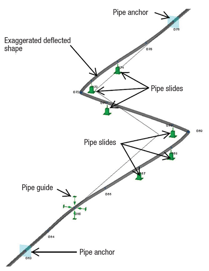
Figure 1. Long pipe runs can be complicated by thermal expansion and contraction, and the distances must be determined
Pipe-induced forces on equipment
Process equipment, particularly devices with rotating components, such as pumps and compressors, are sensitive to forces applied by piping. Reduced seal life and premature bearing wear can result from large forces applied to nozzles. Atmospheric tanks and pressure vessels also have load limits. Loads due to gravity from small-bore piping are generally not a major concern, but loads induced by thermal expansion can be enormous. There are several strategies to reduce these nozzle loads:
1. Create changes of direction in the piping design to allow flexibility and reduce forces
2. Consider designing cold spring into the piping during installation
3. Evaluate the use of spring hangers or supports to reduce thermal and gravity loads across different load cases
4. Consider flexible mounting of the process equipment. Often, high forces can occur on a pump suction — for example, when it is directly connected to a tank with a straight piece of pipe. While the thermal growth or contraction of the pipe segment may only be a small fraction of an inch, the force required to resist the force generated by the expansion can be tens of thousands of pounds. Allowing the pump to float by a 1/16th of an inch can reduce the reaction to a negligible level. This can be achieved by mounting the pump on spring mounts, on a slide base or on threaded rods, allowing them to bend.
5. Expansion/flex joints are an option to reduce loads on equipment nozzles. Unfortunately, they are often incorrectly applied. Due to the pressure thrust forces created by the joint, it is very unlikely that a straight bellows-type flex joint intended to allow axial compression will resolve forces on the pump suction example above, unless the maximum pressure that the system will experience (which is typically test pressure) is very low. These types of joints can be very beneficial, however, in a lateral-displacement configuration, as shown in Figure 2.
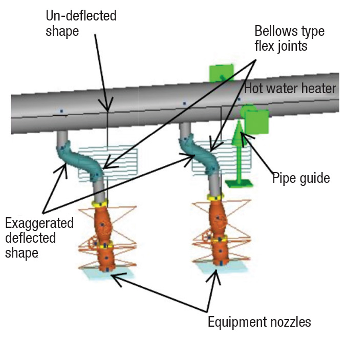
Figure 2. Expansion joints can reduce the loads on equipment nozzles
Sometimes space constraints can complicate supports near equipment, and out-of-the-box solutions need to be found. The images in Figure 3 show supports at pump suctions in a hot-oil system, where the pipe needed to be controlled both laterally and vertically, but also needed freedom to grow away from the pump suction.
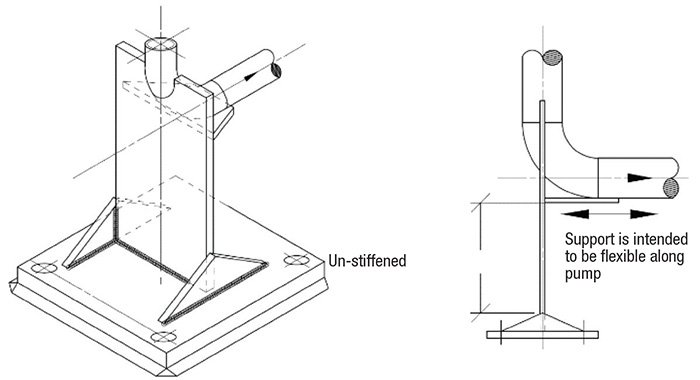
Figure 3. Pipe supports can allow lateral and vertical control, while also allowing freedom to grow
Anchors, guides and slides
Anchors are critical components in any large piping system, and are intended to resist movement from all forces in every direction. They establish the boundaries and the control conditions for all other pipe-stress and support analysis. Anchors are interesting in that they are not just designed to support applied loads, like hangers and guides. Instead, they need to be evaluated for rigidity or stiffness. For example, if an anchor is attached to the top flange of a wide flange beam, the stiffness of that anchor is questionable. Weak axis bending and torsional instability of the beam may reduce the effectiveness of the anchor. If the anchor isn’t relatively rigid, then all other stress and displacement calculations based on that anchor location may be called into question. In designing an anchor, it is critical that the anchor and the structure supporting it are evaluated together to ensure they interact together to achieve the desired performance.
Guides are applied to allow axial movement, generally due to thermal expansion or contraction, and to restrict lateral movement due to wind loads, plant vibrations, or even seismic forces. When a pipe is running along a pipe rack with regularly spaced support beams, the selection and evaluation of the guides is simple. For these situations, many off-the-shelf guides from pipe manufacturers exist. Selecting guides for some other conditions can be more challenging — for example, a pipe running a few feet below roof steel, or vertically a couple of feet off structural steel. In these instances, an off-the-shelf catalog guide probably won’t work without incurring significant costs in additional structural steel. A low-cost solution for examples like these is to use pipe clamps, and either angle iron braces or threaded rod and turnbuckles to create two-force members that provide support in two directions, but allow axial movement via the slight bending of the two-force members (Figures 4 and 5).
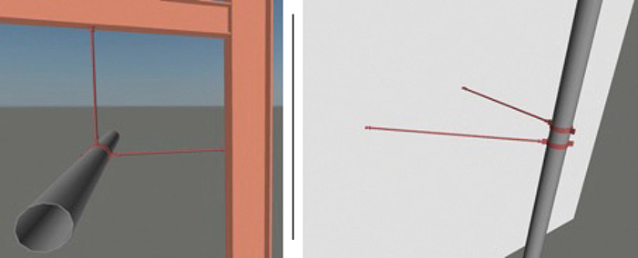
Figure 4 (Left). Pipe clamps and braces can provide support in two directions, while also allowing axial movement
Figure 5 (Right). Axial movement can occur via the slight bending of the two-force guides
Slides are applied in very similar instances as guides and are typically used together in thermal expansion and contraction applications. Slides provide support in one direction (generally perpendicular to the pipe), most commonly supporting a horizontal pipe from below. Like guides on a pipe rack with regularly spaced beams, slides can be selected in a straightforward manner, and there are many off-the-shelf slides available. They are typically selected to allow two degrees of freedom, usually lateral and axial. But once again, in instances where there is not a uniform framing level to support the slides, the alternatives must be investigated. In many cases, a simple clevis hanger can be used, as long as the hanger rod is long compared to the expected displacement of the pipe.
Practical pipe supports
Taking a practical approach to pipe supports can simplify the design of the support system and can usually make supports less expensive. The following are some examples of not-so-practical supports, along with a brief explanation as to why they are impractical, and a better alternative to the example.
Tall post with pipe slide, guide, or anchor on top. A tall post is likely going to experience a relatively large deflection at the top, depending on the section properties of the post, and even with a polytetrafluoroethylene (PTFE; Teflon) or ultrahigh-molecular-weight (UHMW) polymer slide or guide, there is still a friction force that will be applied to the post (Figure 6).
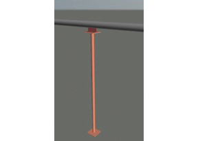
Figure 6. A tall post with a pipe slide, guide or anchor at the top is likely to experience relatively large deflection at the top
The practical approach is to evaluate the expected displacement that necessitated the slide or guide, and check to see if the post and its bottom attachment (weld or base-plate anchors) can tolerate that deflection and bending moment. If it can, then the slide or guide is likely not needed, and a simple U-bolt might suffice (Figure 7).
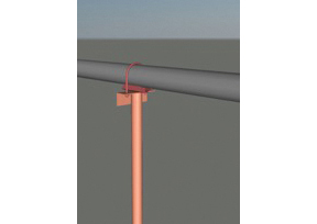
Figure 7. If the post can tolerate bending, then a U-bolt clamp may work as a pipe support
In the case of an anchor on a tall post, the anchor needs to be evaluated for the stiffness of the post to make sure the resulting deflection doesn’t create issues in the rest of the piping system. And again, a U-bolt may be able to transfer all the load the post can handle. Buckling stability of the support needs to be taken into consideration in all cases, but especially if the post is not a closed section member.
Tall post with a cantilever, and either a pipe slide, guide, or anchor. This case is very similar to the one just described, and is commonly seen in retrofitted or expanded plant areas. The principles are the same, but with torsion of the post added (Figure 8).
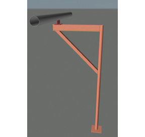
Figure 8. One concern surrounding tall posts with cantilevers involves the torsion of the post
The support is likely flexible enough that slides or guides are not necessary, and this can easily be proven by comparing the expected displacement of the pipe to the deflection resulting from the calculated friction force from the slide/guide. If the friction force is enough to deflect the support to a degree that is equal to or greater than the anticipated pipe displacement, then the slide or guide should not be needed, because the support will bend before the slide or guide begins to move. Again, buckling stability of the support needs to be taken into consideration, especially if the post is not a closed section member.
Long threaded rod hanger and adjustable pipe roller. This is another case that is commonly seen, and like the case of the tall post, the stiffness of the threaded rod hanger is likely not enough to provide the resistance needed to cause the roller to roll, so the roller will just act as an expensive clevis hanger (Figure 9).
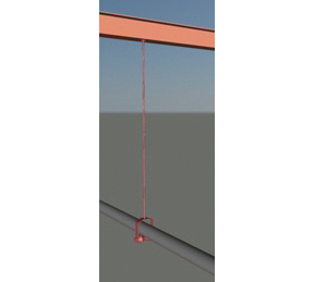
Figure 9. The stiffness of a rod hanger, like the one shown here, likely will not provide the resistance for the roller to roll
Pipe support design and engineering, like all other areas of engineering in an industrial plant, can be challenging. With a little understanding of the various situations, and by not always resorting to an off-the-shelf solution, the design can often be made simpler, more reliable, less expensive and easier to install.
Edited by Scott Jenkins
Author
 Scott Feller is the executive vice president of operations at AMG, Inc. (1497 Shoup Mill Rd, Dayton, OH, 45414; Phone: 937-260-4630; Email: sfeller@amg-eng.com). AMG, Inc. is a full-service engineering consulting firm that provides a broad range of design and construction support services to various chemical processing and related heavy industrial segments.