![]()
Overview: Tube leak was found in Low Pressure (LP) Steam Evaporator at a combined cycle power plant in Oklahoma. This leak was suspected and proved to be Flow Accelerated Corrosion (FAC) damage. This raised concerns about the HRSG design and water chemistry. HRST was hired to assess the HRSG design and assist in identifying areas that should be a priority for future inspections in relation to FAC risk.
Introduction: FAC is a type of corrosion that dissolves the protective magnetite layer on iron surfaces due to contact with water. There are several key points about FAC are as follows:
The Science of FAC: FAC involves the dissolution of surface oxide layer on a component, as shown in Figure 1. This process is influenced by factors such as temperature, pH, flow velocity, flow geometry, and the presence of two phases of steam.
The composition of this surface oxide is also influenced by the chemistry of the fluid (either feedwater or HRSG evaporator water) in contact with the component. Therefore, comprehending the solubility of the two possible oxides, Fe3O4 (magnetite) and Fe2O3 (hematite), which can develop under both reducing and oxidizing conditions, is crucial for gaining insight into the FAC mechanism and its management. Understanding the feedwater chemistry treatment is critical to overall corrosion.
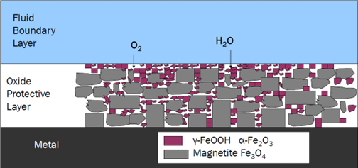
Figure 1: Cross-section of iron surface with oxidizing conditions. Residual dissolved oxygen converts hematite into magnetite.
Feedwater treatments: There are 2 (two) most common feedwater treatments:
1. Reducing all-volatile treatment (AVT(R)): This method employs a neutralizing amine (typically a non-ammonia based one such as morpholine or diethanolamine) and a reducing agent. AVT(R) creates a protective layer on carbon steels, often used in systems for condensate and feedwater up to 300°C (572°F). This protective layer is mostly made of a substance called magnetite (Fe3O4), and it forms through a reaction:
3Fe + 4H2O → Fe3O4 + 4H2 (1) Magnetite formation
2. Oxidizing all-volatile treatment [AVT(O)]: In this treatment, the reducing agent is eliminated combined with ammonia for the neutralizing amine. The ORP typically hovers around 0 mV but might be slightly positive or negative. AVT(O) produces a double oxide layer on the steel, consisting of magnetite (Fe3O4) covered by a layer with a high hematite (Fe2O3) content as shown in Figure 1.
3Fe2+ + 1/2O2 + 3H2O → Fe3O4 + 6H+ (2) Magnetite formation
2 Fe3O4 + H2O → 3Fe2O3 + 2H+ + 2e- (3) Hematite formation
Which water treatment should we use? In short answer, magnetite (Fe3O4) is immensely more soluble than hematite (Fe2O3) as shown in Figure 2. As a result, combined cycle plants that contain no copper alloys and should run AVT(O). In other words, reducing agents should not be added to HRSG during either operation or while shutdown. Instead, AVT(O) can be used on units with all-ferrous feedwater systems with a required minimum oxygen concentration of 5ppb in feedwater to successfully control single phase FAC.
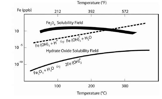
Figure 2: Solubility of Magnetite (Fe3O4) and Hematite (Fe2O3). Source: Comprehensive Cycle Chemistry Guidelines for Combined Cycle/Heat Recovery Steam Generators (HRSGs), EPRI, Palo Alto, CA: 2013, 3002001381
Reducing Agent (aka Oxygen Scavenger) is a chemical substance used to remove or reduce the presence of dissolved oxygen in water. There are different types of commercial oxygen scavenger such as Hydrazine (N2H4), Carbohydrazide [NH2NH2)2CO] (aka Eliminox), and Erythorbate (RC6H6O6 where R is H+, Na+, or amine). Each scavenger has slightly different characteristics. However, they all do not react directly with oxygen, but instead, convert hematite into magnetite as shown in equation 5, an example of hydrazine reducing agent. At the same time, oxygen will react with magnetite to form more hematite. However, as mentioned previously, magnetite is more soluble than hematite as shown in equation 4. This will leave bare iron behind and exposed to FAC corrosion that is dissolved in water.
4Fe3O4 + O2 → 6Fe2O3 (4) Dissolved oxygen converts hematite to magnetite.
6Fe2O3 + N2H4 → 4Fe3O4 + 2H2O + N2 (5) Hematite conversion into magnetite with (reducing agent)
As a result, oxygen scavengers are no longer recommended in modern HRSG chemistry control.
Water chemistry of Oklahoma plant: Oklahoma plant is a three-pressure level combined cycle facility with an evaporative cooled condenser. The HRSG and condenser have all ferrous components, with no copper containing materials. For all ferrous plants, EPRI recommends using AVT(O) for the same reason as mentioned above.
The predominant factor contributing to FAC in the water chemistry at this site is the utilization of carbohydrazide reducing agent into the feedwater. Therefore, for the combined cycle HRSG, it is suggested to evaluate the HRSG’s construction for the absence of copper alloys, typically by evaluating the condenser and large heat exchangers. Then, modification of the HRSG cycle chemistry by discontinuing the use of the reducing agent is recommended. Throughout the transition, regularly check for the presence of copper in the condensate and the High-Pressure (HP) evaporator. Significant increases in copper levels could signal the presence of copper parts within the system. This can be detrimental to both the system components and the steam turbine, especially if the copper is carried over into the steam.
Result: In addition to a water chemistry analysis, the site’s flow circuits were modeled to generate FAC risk factors for those circuits. The results of the analysis were sorted by their associated risk factor. A total of 81 unique areas were found with FAC risk concerns and represented in Level 1 (red), Level 2 (orange), and Level 3 (yellow) risk areas in our analysis. See Figure 3.
The goal of this study is to provide the plant with the necessary information to plan future field testing for FAC damage. HRST recommended that an FAC Inspection Program be developed that, at a minimum, includes the identified Level 1 and Level 2 risk areas WITHOUT LIMITED ACCESS (not gray shaded areas in Figure 3), which narrowed down to only 15 locations as shown in Figure 3. Figure 4 is HRST summary map for inspection of 14 areas that coordinated with the prioritized list of FAC risk areas. If thinning of the metal surfaces is found, areas further down the prioritized list should be added to the inspection program.
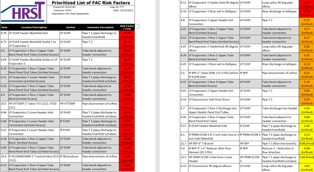
Figure 3: List of FAC UT inspection areas, arranged according to priority.
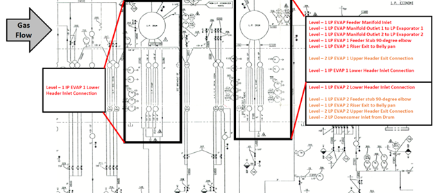
Figure 4: Diagram of FAC location, Priority 1 and 2 locations.