Pneumatically conveyed solid materials inevitably impact pipe walls and other particles, which can create processing and equipment problems. Provided here is an outline of potential problems related to particle impacts and the physics behind them
Among the defining features of pneumatic conveying is the flexibility that can be achieved with pipeline routing for the transport of bulk particulate materials in a totally enclosed environment. Powdered and granular materials can be conveyed vertically up and vertically down, as well as horizontally, in a single continuous routing, just by using bends in the pipeline. By this means, any obstructions in the routing can be avoided simply by routing the pipeline around them.
In traversing a pipeline, however, there will inevitably be impacts between the particles being conveyed and the retaining pipeline. This will be particularly so at each bend in the pipeline, where the particles will be subject to a change in direction, regardless of pipeline orientation. The impacts also lead to reductions in particle velocity. In horizontal sections of pipeline, there will be a natural tendency for the particles to fall to the bottom of the pipeline due to gravity. In this case, the particle impact is likely to be a glancing blow and hence at a low angle of impact. The situation with regard to bends, however, is very different because all the material will have to take the turn, and, as a consequence, there will be a considerable number of particles impacting with the bend wall, as well as particle-to-particle interactions in the turbulence generated. The geometry of the bend is an additional variable here because the radius of the bend will have a major influence on the impact angle. This article provides information about the behavior of pneumatically driven solid materials and the problems that can arise due to impact of the solids on pipe walls and other particles. These include pipe wear, particle degradation, dust formation and others.
Conveying air velocity
Conveying air velocity is a critical parameter in pneumatic conveying. From basic fluid mechanics, pressure drop is directly proportional to the square of the velocity. Therefore, the air velocity must be kept to as low a value as possible to avoid excessive pressure drop. In pneumatic conveying, however, the objective is to have the conveying air velocity maintained at a minimum value that is still sufficient to reliably convey the material. For materials conveyed in dilute phase (suspension flow) this velocity is likely to be in the range of 15 m/s (~3,000 ft/min), and for many materials, dilute-phase conveying is the only option with a conventional pneumatic conveying system. For materials with good air-retention characteristics or good permeability, however, dense-phase conveying may be possible. In this case, the minimum conveying air velocity may be as low as 5 m/s (~1,000 ft/min). A safety margin of about 20% on conveying air velocity is generally recommended. The margin, however, must not be too great because pressure drop, and hence energy required, varies approximately with the square of the velocity.
In pneumatic conveying, engineers generally refer only the velocity of the air (rather than the velocity of particles being conveyed), since this quantity can readily be calculated or measured. The particles in the air stream will be conveyed at a slightly lower velocity. The difference in velocity between the air and the particles in it is generally referred to as the “slip velocity.” The value of the slip velocity will increase with larger particle sizes, higher particle densities and more complex particle shapes (higher surface area).
The routing of the pipeline may include sections where particles are moved vertically up and vertically down in order to cross roads or railways, or to avoid obstructions. Flow vertically up and down presents no undue problems, and is potentially easier, since the minimum conveying air velocity for flow vertically up is generally lower than that for horizontal flow. In reality, there are few cases where this advantage can be exploited, since most pipelines incorporate combinations of both horizontal and vertical pipeline. Most of the time, horizontal pipeline predominates, so conveying air velocities are generally specified in terms of those required for horizontal conveying.
Energy loss
When a material is fed into a pipeline, the particle velocity at the feeding point is essentially zero. It is important, therefore, that the material should be able to be accelerated to its terminal velocity in a straight section of pipeline, either horizontally or vertically. The length of pipeline required for this is termed the “acceleration length,” and will depend upon the particle size, shape and density of the material to be conveyed. For dust and fine powders, this is likely to be on the order of 1–2 m (3–6 ft), but for small granular particles and pelletized materials, the length may be on the order of 5–6 m (16–20 ft). Within the acceleration region, however, the pipeline should be as straight as possible to allow the particles to reach their terminal velocity as quickly as possible. If bends are placed too close together, before a steady flow is established, the flow could stall and the pipeline may block.
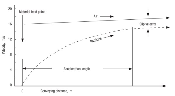
Figure 1. Pneumatically conveyed particles accelerate from the feeding point in the pipeline
The situation is illustrated in Figure 1 [1], which plots the acceleration of the conveyed particles following their feed into a pipeline, at essentially zero velocity, to the point at which they reach their terminal velocity. A significant element of the conveying-line pressure drop, at the start of the pipeline, can be attributed to this acceleration process. In a single-bore pipeline, the values of both the air and particle velocities will continue to increase along the length of the pipeline as the material is conveyed to the discharge point.
It must be recognized that the pipeline will be prone to blockage over much of this acceleration length. It is essential, therefore, that there should be no bends or other possible obstructions to flow in this region. The actual value of the acceleration length will depend very much on the particle size, shape and density of the conveyed material. For fine powders, it may be as little as a couple of meters (~6 ft) but for coarse granular materials it might be 6 m (~20 ft) or more.
Since the material that is fed into a pipeline is essentially at zero velocity, a significant element of pressure drop for the conveying system is that of accelerating the particles from zero velocity to their final terminal velocity at the discharge point from the end of the pipeline. The acceleration pressure drop, ∆pacc, is based on exit values for both air density and conveying air velocity, and can be evaluated from Equation (1); (see box above).
This equation will take into account the acceleration for both the conveying air and the conveyed material. For greater accuracy, should it be needed, account can be taken of the fact that the air will have a significant value of velocity at the pipeline inlet, since it must be high enough to convey the material, and the particles will be at a slightly lower velocity than that of the air at the pipeline outlet by virtue of the necessary slip velocity.
Because air is compressible, the velocity of the conveying air will gradually increase along the length of a single-bore pipeline as the material is conveyed to its destination point. Problems of pipeline wear and particle degradation, as well as power requirements for system operation, will all increase with an increase in velocity. This will be the case for both positive-pressure and vacuum-conveying systems. If high pressure or vacuum is used for conveying, it is essential that the bore of the pipeline be stepped up part of the way along its length to minimize these problems. The location of the step in the pipeline, however, is critical. If it is positioned too early, the conveying air velocity may be below the minimum value for the material being conveyed, and the pipeline will block.
Impact problems
If the material to be conveyed is potentially abrasive, significant wear of the pipeline, and particularly the bends in the pipeline, is likely to occur. If the material being conveyed is potentially friable, significant damage to the material being conveyed may occur, and it is possible that these changes to the material could affect the conveying performance of the material itself. If dust generated from the material is potentially explosive, there is the possibility that such degradation could result in an explosion. As a result of particle impact, particularly against bends, there is potential for heat generation, which can result in particle melting and in the formation of streamers, often called “angel hairs.”
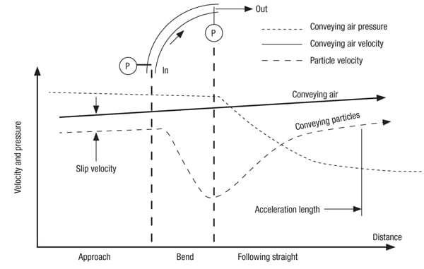
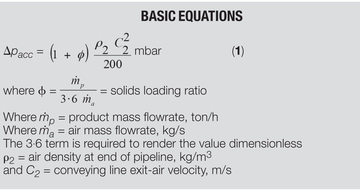
Figure 2. The figure shows changes in pressure and velocity as particles flow through a pipe bend
As a consequence of particle impact, particularly against bends, there will be a significant reduction in particle velocity. These particles will then have to be re-accelerated back to their terminal velocity, which will add significantly to the pressure drop — and hence, energy loss — for the conveying system, as seen by Equation (1). It is not only after the feed point into the pipeline that an acceleration length needs to be established. There will be a significant reduction in particle velocity for particles after exiting a bend, and particularly so after short-radius bends. This situation is illustrated in Figure 2 [1].
Considering the conveying air pressure, there will be a gradual fall in pressure along the entire length of the pipeline. Within the bend itself, there will be a small pressure drop, but the major part of the loss in pressure, as a result of the flow though the bend, will be in the acceleration of the particles back to their terminal velocity following the bend. The two pressure gages included in Figure 2, at the bend inlet and outlet, will give a false reading for the actual pressure drop, which results from the flow of material through the bend. In pneumatic conveying situations, most of the pressure drop that can be attributed to the bend occurs after the bend, in terms of the need to re-accelerate the particles back to their terminal velocity.
Erosive wear
The erosive wear of bends in pneumatic-conveying-system pipelines is well illustrated by the work of Mason and Smith [2]. They carried out tests on 25- and 50-mm (1- and 2-in.) square-section 90-deg bends with a flow of alumina particles from vertical to horizontal. The bends were made of Perspex (polymethylmethacrylate) and were constructed with substantial backing pieces so that the change in flow pattern and wear over a period of time could be visually observed. The results from one of their tests are given in Figure 3.
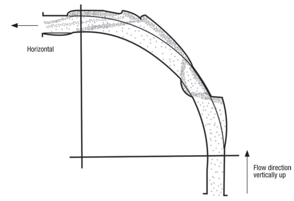
Figure 3. Wear patterns in pipe bends can be influenced by deflected particles
With a new bend, the particles tend to travel straight on from the preceding straight pipeline until they impact against the bend wall. After impact, they tend to be swept around the outside surface of the bend. They are then gradually entrained in the air in the following straight length of pipeline. In Figure 3, the flow pattern is shown after substantial wear has occurred. This shows quite clearly the gradual wearing process of a bend and the effect of impact angle on the material in the process. Erosion first occurred at a bend angle of about 20 deg, which became the primary wear point, as one would expect. After a certain depth of wear pocket had been established, however, the particles were deflected sufficiently to promote wear on the inside surface of the bend, and then to promote a secondary wear point at a bend angle of about 75 deg.
A small tertiary wear point was subsequently created at a bend angle of about 85 deg. If such a highly reinforced bend were to be used in industry, in preference to replacing worn bends, the deflection from the latter wear points would probably cause erosion of the straight section of pipeline downstream from the bend. Because this pattern of particle deflection in worn bends is now well recognized, some companies manufacture steel bends with thicker walls. They are also slightly thicker on the inside surface to allow for the fact that particles can be deflected to the inside surface, as illustrated in Figure 3.
Impact angle and surface material. A curve presented by Tilly [3], and shown in Figure 4, illustrates the variation of erosive wear with impact angle for two different surface materials, and is typical of the early work carried out to investigate the influence of these variables. Both materials showed very significant differences in both erosion rate and the effect of impact angle. These materials do, in fact, exhibit characteristic types of behavior that are now well recognized. The aluminum alloy is typical of ductile materials: it suffers maximum erosion at an impact angle of about 20 deg, and offers good erosion resistance to normal impact. Glass is typical of brittle materials: it suffers severe erosion under normal impact, but offers good erosion resistance to low-angle, glancing impacts.
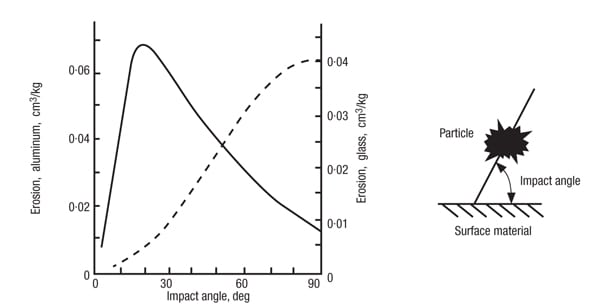
Figure 4. Impact angle is an important variable for erosive wear of various surface materials
These tests were carried out with sand particles sieved to particle sizes of between 60 and 125 μm. The particles were impacted at a velocity of about 100 m/s, since they were undertaken specifically for the investigation of the potential wear of aircraft engines. That brittle and ductile materials respond to erosion in very different ways can be clearly seen from Figure 4, and it is obvious that different mechanisms of material removal must be involved. Note that the two vertical axes relate to the two different materials that were eroded, and that they have very different scales.
Theories proposed. From early thoughts on the matter, it was suggested that for ductile materials (annealed low-carbon steel, copper, aluminum and so on), removal of material occurs predominantly by plastic deformation. No cracks propagate ahead of the cutting particle and the volume removed is due entirely to the cutting action of the particle, rather like the cutting edge of a machine tool. For brittle materials (glass, basalt, ceramics, cast iron, concrete and so on), it was thought that material removal occurs in large part due to the propagation of fracture surfaces into the material.
These erosion processes, however, have subsequently proved to be less straightforward. Photographs taken of impact craters, produced as a result of single-particle impact studies, have shown clear evidence that melting of the pipe material can take place. The melting only occurs over a small part of the impact crater, but it must be considered to contribute to the erosive wear process.
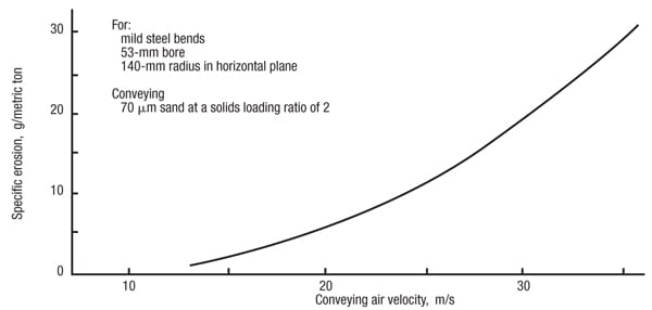
Figure 5. Erosive wear is also influence heavily by particle velocity in pipeline bends
Influence of velocity. The author has undertaken research into the erosion of pipe bends in pneumatic conveying systems at velocities appropriate for dilute-phase suspension flow. Tests were carried out over a range of conveying air velocities from 15 to 35 m/s (3,000 to 7,000 ft/min). Steel bends of 53 mm (2 in.) bore having a ratio of bend diameter, D, to pipe bore, d, of about 5:1 were eroded by 70-μm sand. Over the ranges tested, the velocity exponent was found to be consistent at 2.65. A graph showing the influence of conveying air velocity on the specific erosion of the bends is given in Figure 5 [1].
The solids-loading ratio is the dimensionless ratio of the mass flowrate of the bulk particulate material conveyed, to the mass flowrate of air used to convey the material. For dilute-phase, suspension-flow conveying, solids-loading ratios are typically up to about 15. For low-velocity, dense-phase conveying, solids-loading ratios generally need to be greater than about 40.
The erosion is in terms of the mass of metal eroded from a bend per ton of sand conveyed through the bend. With a velocity exponent of 2.65, this means that the wear rate will increase by a factor of six with a doubling of the air velocity. This explains why the curve rises so steeply in Figure 5. If a positive-pressure conveying system operates at a pressure of 1 barg (15 lb/in.2), a doubling of the velocity will be achieved in a single-bore pipeline discharging to atmospheric pressure. With a vacuum conveying system, a doubling in velocity will be achieved with a system exhausting at 0.5 bar absolute (7.5 lb/in.2). In such a system, a bend at the end of the pipeline will wear approximately six times as fast as a bend at the start of the pipeline.
If an abrasive material is to be conveyed, therefore, it would always be recommended that the pipeline be stepped to a larger bore partially along its length in order to limit the maximum value of velocity achieved, in order to minimize the erosive wear of bends toward the end of the pipeline. It is essential, of course, that the step to the larger-bore pipeline is correctly positioned along the pipeline, for if the velocity falls below the minimum value of conveying air velocity at the step, the pipeline is likely to block at this point.
Particle degradation
In some bulk-solids-handling processes, intentional breakdown of the material is required (crushing, grinding and comminution). In many handling and storage situations, however, unintentional breakage occurs. This is usually termed degradation or attrition, depending on the mechanism of particle breakage. Bulk materials, when pneumatically conveyed, will impact against bends in the pipeline, and there may be a significant amount of particle-to-particle interaction. There may also be frequent impacts against the pipeline walls, and particles sliding along the pipeline walls in low-velocity, dense-phase flows. These collisions and interactions will produce forces on the particles that may lead to their breakage.
Particle breakage. If particle breakdown occurs easily, the bulk solid is said to be friable. Tendency for particle breakdown occurs by three main mechanisms. The first is a tendency to shatter or degrade when the bulk solid is subject to impact or compressive loading. The second is the tendency for fines and small pieces to be worn away by attrition when bulk solids either rub against each other or against some surface, such as a pipeline wall or bend. The third is the tendency for materials, such as nylons and polymers, to form “angel hairs” when conveyed, as a result of micro-melting, which occurs to due to the frictional heat of particles sliding against pipeline walls.
Of all conveying systems, dilute-phase conveying probably results in more material degradation and attrition than any other. This is because particle velocity is a major factor in the problem and, in dilute-phase conveying, high velocities have to be maintained. The potential influence of a pneumatic conveying system on a material is demonstrated in Figures 6 and 7. This is a consequence of conveying a friable material at a high velocity in dilute-phase suspension flow in a conveying system with a large number of small-radius bends [1].
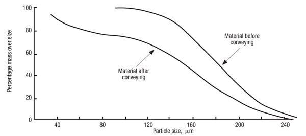
Figure 6. Pneumatic conveying can shift the cumulative particle size distribution of a material, especially for friable solids
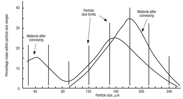
Figure 7. Pneumatic conveying can affect the fractional size distribution of a friable material
Figure 6 shows the influence on the cumulative particle-size distribution for the material before and after conveying. The mean particle size, based on the 50% value, has changed from about 177 to 152 μm. The really significant effect, however, is shown in the fractional size-distribution plot in Figure 7. In this alternative (and essentially magnified) plot, the potential effect of degradation on the material can be clearly seen. A considerable number of fines are produced, and even on a percentage mass basis, these cause a significant secondary peak in the particle-size distribution.
Operating problems. Particle degradation can cause problems in a number of areas because of changes in particle shape and particle-size distribution that can result. It is a particular problem with chemical materials that are coated, for it is the coating that is generally the friable element of the resulting material. Plant operating difficulties are often experienced because of the fines produced, and problems in handling operations can also result after the material has been conveyed.
Apart from the obvious problems of quality control with friable materials, changes in particle shape can also lead to subsequent process difficulties with certain materials. The appearance of the material may also change, making it not as readily sold. Changes in particle-size distribution can affect flow characteristics, which in the extreme, can change a free-flowing material into one that can only be handled with great difficulty, and with materials intended for subsequent sale, this can lead to customer problems.
Filtration problems. In pneumatic conveying systems, plant-operating difficulties can result if degradation causes a large percentage of fines to be produced, particularly if the filtration equipment is not capable of handling the fines satisfactorily. Filter cloths and screens will rapidly block if they have to cope with unexpectedly high flowrates of fine powder. The net result is that there is usually an increase in pressure drop across the filter, and this could be a significant proportion of the total pressure available in a low-pressure system.
Flow problems. In many systems there is a need to store the conveyed material in a hopper or silo. Flow functions can be determined for bulk particulate materials, from which hopper wall angles and opening sizes can be evaluated, to ensure that the material flows reliably at the rate required. A change in particle-size distribution of a material, as a result of conveying operations, however, can result in a significant change in flow properties. Thus, a hopper designed for a material in the “as-received” condition may be totally unsuitable for the material after it has been conveyed. As a result, it may be necessary to fit an expensive flow aid to the hopper to solve the problem.
Potential explosion problems. Many solid materials, when they occur in a dust cloud, can ignite and cause an explosion. Dust clouds are clearly quite impossible to avoid within a pneumatic conveying system, and so this poses a hazard with regard to the safe operation of such systems. Of those materials that are potentially explosive, research has shown that it is only the fraction of the material with particle sizes less than about 200 μm that poses the risk of explosion. Degradation and attrition caused by pneumatic conveying, however, can result in the generation of a considerable number of fines, particularly if the material is friable. Even if the material did not present a problem with respect to explosions in the “as-received” condition, the situation could be very different after the material has been conveyed [4].
The influence of velocity. The results of a program of tests [1] carried out with 5-mm spherical aluminum-oxide particles impacted at 90 deg against a steel target are presented in Figure 8. In this plot, the experimental data have been included to show how the relationship was derived and to show the limits of scatter in the results.
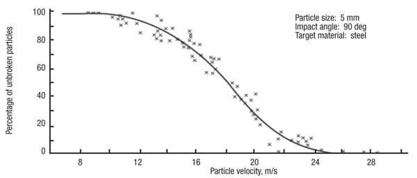
Figure 8. These data show how particle velocity can influence the degradation of 5-mm aluminium oxide particles
Figure 8 shows that there is a very rapid transition in particle velocity from zero breakage to total degradation. Below a particle velocity of about 9 m/s, only elastic deformation occurs and there is essentially zero particle degradation. Above a particle velocity of about 25 m/s, however, the stress induced by the impact is always sufficient to damage every particle. It is interesting to note that within the transition region, the number of unbroken particles at any given velocity is very consistent, and that a smooth transition is obtained from one extreme to the other over this range of velocity.
The influence of surface material. With erosive wear of surface materials, it has been found that the resilience of the surface material can have a significant influence on erosive wear, and that rubber and polymers can offer better wear resistance than metals having a very high hardness value in certain cases. Since the mechanisms of erosion and degradation have many similarities, it is quite possible that resilient materials could offer very good resistance to particle degradation.
The results of tests carried out on four different target materials with the 5-mm spherical aluminum-oxide particles are presented in Figure 9. In each case, the targets were 5-mm thick and they were impacted by the aluminum oxide particles at 90 deg. This shows very clearly that target material can have a very marked effect on degradation.
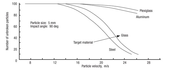
Figure 9. Different target materials, including glass, steel and aluminum, affect the degradation of aluminium oxide particles
Although there is little difference in the maximum value of particle velocity at which no degradation occurs, varying from 12 m/s for steel to about 17 m/s for Plexiglas (poly methylmethacrylate) and aluminum, very significant differences exist in the transition region between no degradation and total degradation. In the case of the steel and glass targets, the transition is very rapid. For the aluminum and Plexiglas, however, the transition is very slow, and so a high-velocity impact against these materials would only result in limited damage occurring.
The influence of particle impact angle. Particle impact angle is the same as that used in the above erosive-wear work (Figure 4). Impact angle has been shown to be a major variable with regard to the erosive wear of surface materials, and hence is an important consideration in terms of material selection and the specification of components such as pipeline bends. In relation to particle degradation, it is equally important, for as the impact angle reduces, so the normal component of velocity decreases. This will have a direct bearing on the deceleration force on the particles. The results of a comprehensive program of tests carried with the 5-mm aluminium-oxide particles aimed at investigating the influence of particle-impact angle are presented in Figure 10 [1].
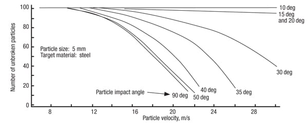
Figure 10. These data show how different impact angles affect the degradation of aluminum oxide particles
Figure 10 shows that there is little change in the response to degradation until the impact angle is below about 50 deg. There is then a very marked difference in performance, with only small incremental changes in impact angle. With a decrease in particle-impact angle, it would appear that there is little change in the particle velocity at which the onset of degradation occurs. The transition from zero degradation to total degradation, however, becomes an increasingly more gradual process as the particle-impact angle decreases. At impact angles of 15 and 20 deg, it would appear that this transitional process is spread over a very wide range of velocity values. At an impact angle of 10 deg, however, there is a significant change once again, in that no particle degradation was recorded at all up to 30 m/s.
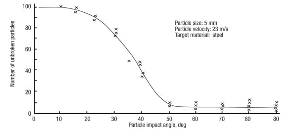
Figure 11. This graph takes a slice of particle-impact data from Figure 10 at a particular particle velocity and shows the affect on particle degradation
In Figure 11, an alternative plot of the data in this program of tests is presented. This is effectively a slice taken from Figure 10 at a particle velocity of 23 m/s. This graph shows that tests were carried out at regular increments of impact angle (about 10 deg) between 10 and 90 deg. This plot shows quite clearly that at impact angles below about 12 deg, no degradation occurs, and that at impact angles above about 55 deg, the degradation remains essentially constant at the maximum value for this particular impact velocity.
Particle melting
Particle melting is a form of material degradation that often occurs in pneumatic conveying plants handling plastic-type materials, particularly in pelletized form. If a conventional pipeline is used, materials such as polyethylene, nylon and polyesters can form cobweb-like agglomerates. They are variously given names like “angel hairs,” “raffia,” “snake skins” and “streamers.”
Such agglomerates frequently cause blockages at line diverters and filters, which require plant interruption to remove them. Equipment is generally installed at the terminating end of the conveying system for this purpose. Such equipment is necessary because streamers also cause material rejection by customers (because the presence of these contaminants in the product is undesirable).
Mechanics of the process. The streamers are caused by the pellets impacting against pipe bends and “sliding” along the inside surface of the pipeline. A considerable amount of energy is converted into heat by the friction of the two surfaces when they touch. If the surface of the pipe is smooth, the pellet will slide. This contact, though momentary, decelerates the particle by friction, which is transformed into heat. This friction is generally sufficient to raise the temperature at the surface of the pellet to its melting point. To a certain extent, this is analogous to the thermal model proposed for erosive wear.
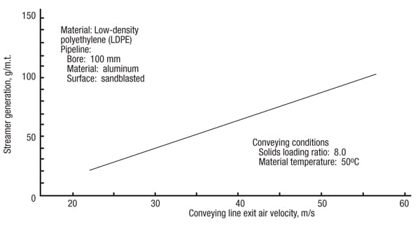
Figure 12. Low-density polyethylene (LDPE) pellets can degrade by forming “streamers”
Influence of variables. The onset of the formation of these angel hairs or streamers is the result of a combination of conditions. Particle velocity is the most important, but it also depends upon the temperature of the pipeline, the temperature of the pellets, and the solids-loading ratio of the conveyed material. The influence of conveying-line exit-air velocity for low-density polyethylene is shown in Figure 12 [ 5].
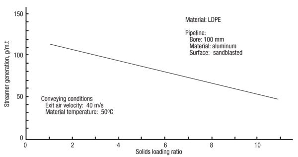
Figure 13. Solids-loading ratio can have an effect on the degradation of LDPE
The influence of solids-loading ratio for this same material is given in Figure 13. In each case, the degradation of the material is expressed in terms of the mass of streamers and fines produced, in grams, per metric ton of low-density polyethylene conveyed.
Pipeline treatment. The formation of streamers and fines can be reduced quite considerably by suitably treating the pipe wall surface. A roughened surface is necessary in order to prevent the pellets from sliding. If the surface is too rough, however, small pieces will be torn away from the pellets instead, and a large percentage of fines will result. It will also have an adverse effect on the pressure drop, and hence on material conveying capacity.
Although the results presented in Figures 12 and 13 were obtained from tests carried out with pipe surfaces roughened by sandblasting, this treatment is not recommended, as it will result in the generation of a large percentage of fines. Also, this roughness is relatively shallow in depth and an aluminium surface will wear so that the pipe must be re-treated in six to twelve months.
A more recent innovation is to attach a small-diameter wire to the inner surface of the pipeline, arranged in a spiral. This essentially acts as a “tripwire” for any particles that are sliding. On impact with the wire, any particles impacting it will be thrown back into the conveying air flow.
Edited by Scott Jenkins
References
1. Mills, D., “Pneumatic Conveying Design Guide,” 3rd Ed., Butterworth-Heinemann (Elsevier Ltd.), 2016.
2. Mason, J.S. and Smith, B.V., The erosion of bends by pneumatically conveyed suspensions of abrasive particles., Powder Technology, vol. 6, pp. 323–335, 1973.
3. Tilly, G.P., “Erosion caused by impact of solid particles. Treatise on materials science and technology,” Academic Press Inc., vol. 13, pp 287–319, 1979.
4. Mills, D., Safety Aspects of Pneumatic Conveying. Chem. Eng., April 1999, pp. 84–91. April 1999.
5. Paulson, J., Effective means for reducing formation of fines and streamers. presented at Process Conf. on Polyolefins, Society of Plastics Engineers, Houston, 1978.
Author
 David Mills is an academic engineer and pneumatic conveying consultant in the U.K. (9 Cherry Orchard, Old Wives Lees, CT4 BQ8, Kent, Canterbury, U.K.; Phone: 041-332-7090; Email: [email protected]). He was, for many years, Professor of Bulk Solids Handling at Glasgow Caledonian University in Scotland. He is currently Conjoint Professor at the University of Newcastle in New South Wales, Australia, and Adjunct Professor at the University of the Witwatersrand in Johannesburg, South Africa. His “Pneumatic Conveying Design Guide” — started in 1979 with U.K. government funding as it was recognised as a subject significantly lacking in design capability and understanding — is now in its third edition. He has contributed several articles to Chemical Engineering since 1990. Mills has expertise in system design and troubleshooting, and also investigates product degradation and high-pressure blow-tank systems. He holds a Ph.D. in engineering and is the author of over 80 papers on pneumatic conveying, covering topics such as system design and performance.