Using gravity to initiate flow in the discharge of solid materials from bins and hoppers is the simplest, and often best, approach to solving solids-handling challenges. However, not all solid materials flow well by gravity alone. The propensity for fine solid materials to cake can lead to flow problems that will adversely affect your process. For situations where material caking disrupts gravity flow, a range of flow aid approaches are available to solve a variety of flow issues. This article discusses the operation of passive and active flow aids, and points out considerations for their use.
Particle caking
 |
|
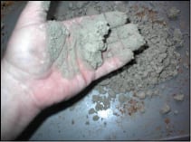
Figure 1. Many solids exhibit caking or packing
properties when under pressure, such as that seen in a bin or silo |
Cohesive strength is a characteristic of many materials, and fine solids tend to cake, agglomerate and pack because of it. But what is cohesive strength? Most of us understand it intuitively — gently reach into a box of laundry detergent and the detergent sifts or flows through our fingers, but squeeze or compact the material, and it retains its shape and no longer flows over our fingers (Figure 1). This effect is due to compaction or consolidation pressure, which is a key factor in bulk-solids handling. Consider that inside a bin or silo, the pressures acting on the solids are very high and can easily cause the material to consolidate.
Measuring the flow properties of a bulk solid is critical to understanding how it will flow in a new system, or why it is troublesome in an existing system. Knowing the type of flow pattern that develops in a bin or silo is a prerequisite to reliable handling. Two major types of flow patterns can develop in solids flow: funnel flow and mass flow. In funnel flow, whenever any material is discharged from a container, some material moves while the rest remains stagnant. Funnel flow can lead to ratholing, erratic flow, flooding and segregation. When material flows in mass flow mode, all the material moves whenever any is withdrawn from the bin or hopper. This means that the material is sliding at the walls of the container and segregation is minimized, while ratholing and flooding generally do not occur.
Several test methods are available to identify a material’s flow properties. The Jenike Shear Test method is the most important and has been the standard in the U.S. and Europe. The ASTM International consensus standard D 6128-06 for measuring bulk-solids flow properties is based on it. The method is named after Andrew Jenike, a pioneer of the theory of bulk solids flow. Jenike’s scientific approach to the storage and flow of bulk solids, developed in the 1950s, remains relevant today.
 |
|
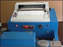
FIGURE 2. The Jenike Shear Test Method,
for determining a solid’s flow properties, is used in an ASTM standard |
The device used for the Jenike Shear Test is considered a linear direct shear tester (Figure 2). Other devices include Schulze’s Ring Shear Tester, Brookfield Annular Shear Tester, Peschl’s Rotary Shear Tester and the Freeman Tester. Keep in mind that all of these devices compare their results to the Jenike Shear Test results.
Once information is gathered on the flow properties of a solid material, it may be necessary to select a gravity flow aid to overcome particle caking. The following discussion of flow aids categorizes the devices into two types: active and passive.
MECHANICAL FLOW AIDS
Mechanical, or active devices include vibrating dischargers, vibrators, agitations and forced-extraction devices. Air-operated devices, such as air blasters, air pads, air fluidizers and so on, are also included in the active flow-aid discussion.
Vibrating bin discharger
 |
|
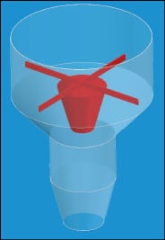
FIGURE 3. Eccentric weights are at work
in a vibrating bin discharger |
Some mechanical flow-aid devices rely on internal components to force material to flow. Probably the most commonly used device is the vibrating bin discharger (Figure 3). A vibrating discharger can accommodate hopper openings from about 3 to 15 ft and is intended to keep material completely live over a hopper outlet’s entire cross-sectional area. This type of device is hung from a storage bin by rubber bushed links, and incorporates a rubber skirt to prevent leakage and to isolate the bin from the vibrations. Vibration is transmitted through an outer shell and into an internal dome or cone-shaped baffle by a motor with eccentric weights. A cohesive bulk solid can be broken up and made to flow, depending on the amplitude of vibration applied.
Several issues should be considered when using a vibrating bin discharger, including the following:
• It must discharge over its entire cross-sectional area and be operated according to manufacturer instructions, which usually require it to be cycled on and off intermittently. Otherwise, small preferential flow channels will form, affecting solids flow and potentially causing structural problems
• If solids in a bin are flowing in a funnel-flow pattern, the diameter of the discharger must be larger than the ratholing capability of the material (as long as the discharger cross-section is fully live)
• A discharger cannot control solids flowrate and it is not a feeder. As such, it requires a feeder to control the discharge rate to the process or system
• Pressure-sensitive materials usually do not flow well through dischargers. They tend to pack in the annulus created by the baffle and outer shell
Vibrators
Vibrators have long been used to enhance material flow. Sledgehammers or mallets are probably the most common flow aid of this type used. These can be the the least expensive way to encourage flow in a bin (and in some cases modify the shape of a bin). There are however, vibrators available that will essentially replace the sledgehammer.
 |
|
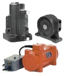
FIGURE 4. Vibrators can be mounted on the
side of a bin to initiate flow |
Vibrators can be mounted on the side of a bin or chute in an attempt to initiate flow. These vibrators can be air- or electrically operated and come in all shapes and sizes. Rotary, piston, turbine, linear, electromagnetic, eccentric and several others are specific types of vibrators (Figure 4). Some types are designed to provide high-frequency, low-amplitude vibration to a surface. Others are used to generate high-amplitude vibrations, such as those required to provide a “thump.” Battering rams are even used to bang the side of a large bin in order to move material.
However, vibrators should be used with caution. Here are a number of considerations:
• The material in the bin should not be pressure-sensitive. If the material can be squeezed to form a “snowball,” it is likely to pack inside the bin, due to vibration
• Do not operate a vibrator unless the solid material has somewhere to move. The feeder must be operating or the gate opened; otherwise packing will occur
• Chutes are a good place to mount vibrators, as they will enhance flow down a shallow chute
• Be aware of the vibrator’s effect on the structural integrity of the bin
Agitation
 |
|
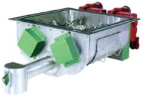
FIGURE 5. Agitators produce a downward flow
of solids into a discharge auger |
 |
|
FIGURE 6. A cone unloader has a vibrating cone
that extends into the product to initiate flow |
Devices that agitate a solid product are available, and are typically composed of multiple segmented helical sections that slowly rotate within the body of the discharger (Figure 5). This produces a downward flow into a discharge auger that controls the rate of withdrawal. For agitator-type flow aids, consider the following:
• The conditioning auger operates slowly (about 1–2 rpm) to minimize consolidation
• The size of the unit is usually based on the arching dimensions of the material
• These flow aids can have difficulty with flaky or cohesive materials
Cone unloading
A cone unloader is a device similar to a vibrating-bin discharger but it has an internal cone that is raised into the product and vibrated to initiate flow (Figure 6). This device uses a vibrating cone that is intended to promote mass flow and break bridges. It can be used as a gate as well as a discharging device. Cone unloaders are dust-tight, and if they fail, they will fail safe-closed.
Forced extraction
 |
|
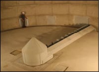
FIGURE 7. Traveling-auger unloaders work
well with woodchips, biomass and granular or flaky materials |
Traveling-auger unloaders have been in use for years and are typically used to discharge solids from flat-bottomed bins and silos. These heavy-duty, track-driven systems are designed for continuous operation under the most challenging conditions (Figure 7). Traveling augers cause solid material to discharge, dragging products to a centered discharge point. Traveling augers work well with woodchips, biomass and granular or flaky materials. This type of flow aid occupies minimal headroom.
Cone-bottom systems
 |
|
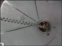
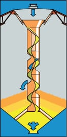
FIGURE 8. Cone-bottom systems have screws
that rotate around their own axes, while also advancing around the silo |
Cone-bottom storage and reclaim systems work for materials with moderate flow characteristics (Figure 8). The screw rotates about its own axis, moving material toward the center of the silo outlet. At the same time, the screw slowly advances, sweeping around the entire silo hopper. Material is discharged to the center of the silo hopper, then flows down through a central chute below the hopper and into a discharge auger or conveyor for transfer out of the silo and to the next step in the material handling process. The cone bottom unloader uses a rotating auger to provide product withdrawal and a collecting auger to discharge material away from the silo. This type of flow aid handles dry meals, chemicals, plastics and small-particle wood waste.
Rotating-arm unloader
Some materials, such as marl limestone, sludge and clay, do not respond well to vibration. However, a rotating-arm discharger may be used. These devices use a traveling arm to discharge product. They drag material to a central discharge point. Advantages of the rotating-arm unloader include first-in, first-out material flow, gentle handling of material, and repeatable, accurate discharge rates, creating consistency in operation. The rotating arm unloader works well with sticky materials, such as synthetic gypsum, sludge and others.
Cleanout devices
 |
|
FIGURE 9. Giro
whips are powered by compressed air and manipulated by operators |
Cardox systems use a tube or cartridge that is filled with liquid carbon dioxide. When the cartridge is energized by the application of a small electrical charge, the chemical inside instantly converts the liquid CO2 to gas. This conversion expands the CO2 volume and builds up pressure inside the tube until it causes the rupture disc at the end of the tube to burst. This releases the CO2 (now 6,000 times its original volume) through a special discharge nozzle to create a powerful heaving force, at pressures up to 40,000 psi. Keep the following in mind:
• The rupture (shear) disc bursts, releasing a heaving mass of carbon dioxide, which breaks apart the surrounding solid material
• This is a dangerous approach to encouraging flow from a bin, and is used in specialized situations
• Cleanout devices can create large boulders of solid material that, when falling, can cause structural damage to equipment
Giro whips (Figure 9) are another type of cleanout device. They are powered by compressed air and maneuvered by an operator who manipulates the cleaning head. They use a variety of whips and cutting edges. An advantage of this type of device is that they are mobile and can be easily positioned at the cleaning location.
Aeration
 |
|
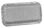
FIGURE 10. Air pads discharge air at
bin walls to provide localized fluidization of products |
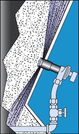
Air pads (Figure 10) have been used for years and work by discharging air along the walls of bins and hoppers. They provide localized fluidization to aid flow, and require several pads to be effective. Users must be careful, because the pads may also obstruct flow.
Fluidizers are a popular means of achieving locally fluidize product along the walls of a hopper (Figure 11). Fluidizers basically work by undercutting solid material to provide localized fluidization. They can be mounted externally so that aid can be obtained without emptying the bin.
 |
|
FIGURE 11. Fluidizers are an alternate
method to generate localized fluidization, but they are mounted externally |
Air blasters inject high-pressure air into a bin or silo that has trouble with arching, ratholing or both. An air blaster uses air or nitrogen that is stored in a tank at about 80 to 100 psi. Air blasters also have a piston-sealed exhaust and quick-acting valve to fire the high-pressure air at an arch or rathole. The expanding air breaks bridges and causes material to flow.
NON-MECHANICAL AIDS
Non-mechanical solids-flow aids are also known as passive aids, and there are several types. Among them are powders and chemicals that can be added to some solids to improve their flowability. Flow aid chemicals, such as fumed silica, can improve flow, reduce caking and improve storage stability.
Freeze conditioning agents
These flow aids are available for products that are exposed to sub-freezing conditions. Freeze-conditioning agents interfere with the bonds between the solid material and frozen moisture, creating a slush instead of a frozen block. Freeze-conditioning agents serve to reduce a solid’s arching dimensions.
 |
|
FIGURE 12. Cone-in-cone devices are
|
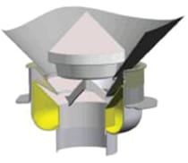
Cone-in-cone
This approach to aiding solids flow involves a conical hopper mounted within another larger conical hopper. The design is intended to minimize hopper height and promote mass flow (Figure 12). The inner cone, which is open at the top and bottom, is designed for mass flow and it forces the material to flow along the walls of the shallow outer cone. The cone-in-cone design is used to perform the following:
• Help convert a funnel flow pattern to mass flow
• Prevent segregation
• Promote blending
The surface finish of the hoppers is critical to ensure mass flow.
Letdown chute
 |
|
FIGURE 13. Letdown chutes
lower solid material gently into the bin |
 |
|
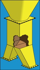
FIGURE 14. Splitters prevent
stagnation of material when one discharge stream is stopped |
When dealing with solid materials that are fragile and tend to break down easily when handled using bins and feeders, a letdown chute may be used to minimize attrition (Figure 13). When using the letdown chute, the material is deposited in the top of the spiral chute, and is lowered to the bottom of the bin, where it gently spills out of the openings provided.
Splitter
Often, a process requires two discharge streams to provide product to two different processes, conveyors and so on. Most of the time, a pant-leg-type hopper is used to discharge to the two points. This approach will work if both legs of the pant-leg hopper are discharging simultaneously. If, however, one leg of the pant leg is stopped, most of the material in the bin becomes stagnant.
The preferred way to provide multiple discharge points is to use a splitter concept (Figure 14). If one leg becomes blocked, the vertical section above it will allow the preferential flow channel that forms due to the flowing leg, to expand within it such that the product at the outlet is fully live. This prevents the stagnation created by the stopped pant-leg hopper.
Edited by Scott Jenkins
Author

Joseph Marinelli is president of Solids Handling Technologies, Inc. (1631 Caille Court, Fort Mill, SC 29708, phone: (803) 802-5527; Email: joe@solidshandlingtech.com). Marinelli is a bulk-materials-handling expert who has taught hundreds of highly acclaimed engineering seminars. Since 1972, he has been active in testing bulk solids and consulting on materials-handling systems design. Marinelli has worked with Jenike & Johanson, Inc., world-renowned experts on solids handling. He received a B.S. degree in mechanical engineering, from Northeastern University in Boston, Mass. He lectures frequently, on solids-flow principles and flow-property testing, and has authored several papers and an encyclopedia section on the subject. Since 1997, he has been involved with popular seminars at the University of Wisconsin in the areas of bin and feeder design and solids-flow-property testing. He is also a columnist for www.powderbulksolids.com.