Testing steam-trap stations can be very easy if the plant provides the correct equipment, training and commitment to the steam-system management program
When it comes to testing steam traps, a frequently asked question is, “what is the best method?” The true answer is to use all of the technologies available today. No single test method provides the best results all of the time for the variety of applications, installations and steam-trap types in industrial plant operations. Therefore, all tools available in the marketplace should be implemented and used where appropriate. So, what are these tools? They can be segmented into three categories:
- Visual
- Temperature
- Ultrasound
Becoming proficient with these tools is like riding a bicycle — the more you ride the bicycle, the better you become. Practice and gaining the knowledge of the methods is the key to successfully using the different devices.
Visual methods
The use of a testing-tee valve arrangement, testing-valve combination, or an inline sight glass for reviewing the steam trap discharging to the atmosphere is a very effective way of testing steam traps (Figures 1 and 2). This visual method can accurately determine the following conditions:
- Blow-through steam or a failed open condition
- Severe steam leakage
- Under-sizing
There are some negatives to any testing method and the visual method is no exception. The inspector must understand the concept of flash steam and become aware of the difference between flash steam and blow-through steam. There are safety concerns due to the release of hot steam to atmosphere during the testing phase. Finally, there is a small additional cost associated with installing the components that permit online testing.
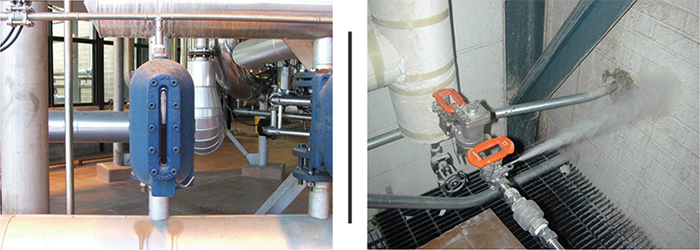
Figure 1 (Left). Shown here is a visual indicator on a steam trap | Figure 2 (Right). A steam trap test valve is shown here
Temperature methods
The relationship between steam pressure and temperature makes temperature measurement extremely helpful in understanding many different operating conditions of steam components that are found in the steam and condensate system.
Infrared (IR) temperature measuring is a very quick and versatile tool for steam systems. Like all testing equipment, IR requires training to ensure success. All diagnostic tools have positive features and negative attributes. It is important to understand the negative attributes to ensure an accurate temperature measurement.
Temperature measurement devices must be an integral part of a steam-trap station testing program. These devices are by no means the only piece of diagnostic equipment that should be used, but they can help provide valuable information that would otherwise not be available.
Estimating steam pressure
Plant engineers can estimate steam and condensate pressures by using temperature-testing devices to detect the temperature of the steam line inlet to the steam-trap station and on the discharge line (Figure 3).
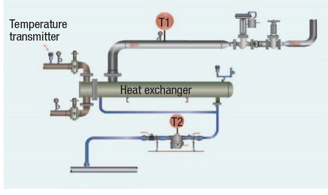
Figure 3. Measuring the inlet and discharge temperatures can provide an estimated steam pressure
Knowing what steam and condensate pressures are present in the system will assist the people performing the steam-trap station testing, enabling them to quickly evaluate system dynamics that can affect the steam-trap station’s operation.
Is the steam trap operational?
A temperature measurement will allow the steam-trap station examiner to determine whether the steam trap is operational or whether the steam trap station is below the expected temperature. If the latter is the case, then the plant should initiate root-cause analysis to determine the source of the problem in the system.
For example, in Figure 4, the temperature on the steam line entering the process is 299°F; therefore, the steam-trap body temperature should be at or close to the inlet temperature.
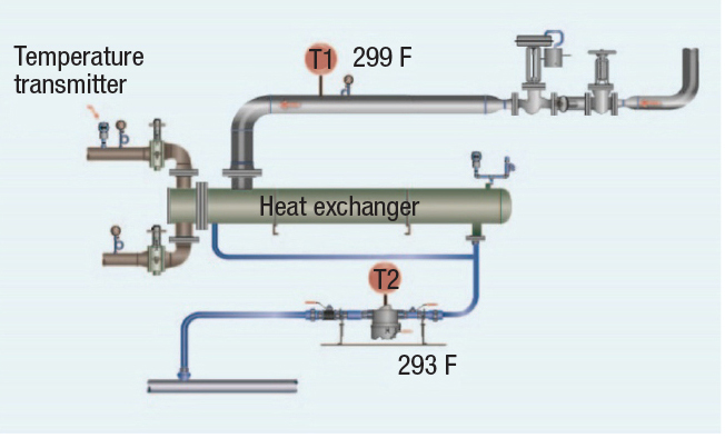
Figure 4. In this setup, the steam inlet and steam-trap temperatures are equal or nearly equal
This is a true statement for 96% of the steam process applications. However, there are a few exceptions when the heat-transfer units have an extremely high condensing rate or when there is a pressure drop in the process. The following three examples make this more clear.
Example 1: Equal temperatures. The inlet and outlet temperatures (process and steam trap) are measured to be the same or nearly equal (Figure 4). This means the steam trap is operational, and further testing can be accomplished.
Example 2: Low outlet temperature. In Figure 5, the steam trap body temperature is very low (210°F) compared to the inlet steam temperature to the process. The steam trap temperature is low, and root-cause analysis needs to be performed to find the reason, such as the following:
- Undersized steam trap
- Fouled strainer
- High back-pressure in the condensate line
- Other causes
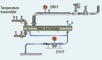
Figure 5. In this example, the steam trap has a low body temperature
Testing steam trap performance
Although surface-temperature measurement can be very useful in evaluating various potential conditions, using it alone for testing steam-trap stations will have a low accuracy for testing steam trap performance. A steam-trap station examiner should be extremely knowledgeable of steam and condensate system dynamics.
Different sources state that if there is a high temperature differential across the steam-trap station, then the steam trap is in good operational condition. If there is no or a very low temperature differential, then the steam trap has failed and is blowing or leaking steam into the condensate system. Temperature measurements must be part of the steam trap station standard operating procedure (SOP) to ensure the steam trap station is operational.
Example 3: High temperature differential across the steam-trap station. Figure 6 indicates a high temperature differential (inlet temperature = 299°F; outlet temperature = 214°F). However, the steam trap is completely failed and is blowing steam into the condensate line. Then why is there a high temperature differential?
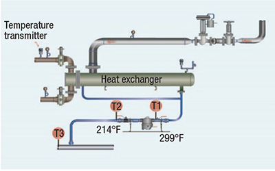
Figure 6. There is a high temperature differential across the steam trap shown here
If steam is blowing into a condensate line that has zero pressure, the steam temperature of the blowing or leaking steam trap must be at 212°F, or the temperature of steam at zero pressure. Now, when the steam passes from a high pressure to a lower pressure, superheat will be generated, but the condensate passing the steam keeps the steam at saturated conditions.
Example 4: Steam-trap station with a low temperature differential. Figure 7 shows a very low temperature differential (inlet temperature = 299°F; outlet temperature = 284°F), which should indicate that the steam trap has failed and is blowing steam in the condensate line. In this example, there is backpressure in the condensate return line, which is normal in most condensate lines due to design, undersizing and elevations. The condensate line pressure will vary depending on the variables. With pressure in the condensate line, the condensate line temperature should be at or close to the saturated temperature at the condensate line pressure.
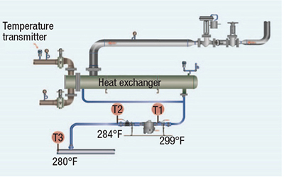
Figure 7. This example shows a low temperature differential across the steam trap
Example 5: Low-pressure systems. There will be a low temperature differential across the steam trap station based solely on the low steam pressures in the steam system and condensate line, as shown in Figure 8. The steam trap could be failed or working properly; the condition of the steam trap is unknown because both conditions will have similar steam temperatures.
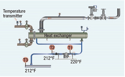
Figure 8. There is a low temperature differential across this steam trap station at low pressure
Measurement procedures
Temperature measurements (Figure 9) need to be taken upstream and downstream of the steam trap station to determine the inlet steam pressure to the steam trap station and the condensate line backpressure.
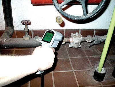
Figure 9. A temperature measurement is being performed in this picture
To achieve a representative temperature, scan the exposed metal surfaces of the upstream and downstream piping/tubing around the steam trap station. Some installations may have several inches exposed, while other installations may only have pipeline components, such as unions, valves or fittings, exposed. The steam-trap station examiner must consider what is available for temperature scanning when incorporating the temperature reading in evaluating the steam trap station operation. The following are suggested:
- Measure the inlet temperature of steam/condensate line to the inlet of the steam trap. A significantly lower temperature than the saturation temperature of the steam line pressure can indicate that there are issues with the steam trap, that flow is reduced due to plugged fittings or strainer screens, or even that the steam trap has been valved off
- Measure the temperature to the inlet of the steam consumer (equipment) and compare it to the inlet of the steam trap. Generally, these temperatures should be close in measurement (±20°F/±11°C)
-Record the reading - Measure the outlet temperature in the condensate line downstream of the steam trap
-There should be some decrease in the outlet temperature versus the inlet temperature
-This measurement can also be used to determine the backpressure present in the condensate line
-Record the reading
In concluding this section, we can say that temperature measurement is an important part of steam-trap station evaluation, but it is only one of the methods. Others are important, too.
ultrasound
When using high-frequency ultrasound, the main question is where the sensitivity should be set to conduct the test. If the testing instrument is set with a sensitivity that is too high, all of the steam traps will test as failed; using too low a sensitivity will indicate that all steam traps are operating properly.
The solution is using a field-proven comparison method, which will provide an accurate test on each steam trap. The comparison method uses three or more test points on the steam trap station. Two of the test points are the sensitivity baseline settings on the ultrasound unit, and the third is for testing the steam trap. The comparison method allows the steam-trap station assessor to establish a base reading to filter out any competing ultrasounds that can be generated upstream or downstream of the steam trap. Without using the comparison method of testing, it is very difficult to assess the steam trap’s performance because the assessor will not know the correct sensitivity setting. Each steam trap will be in slightly different installations and situations in the steam system, so the comparison method is the most accurate method for setting the ultrasound sensitivity.
Sensitivity settings
Most digital ultrasound devices have a stethoscope module. With the stethoscope module, contact each point on the steam trap station, as shown in Figure 10. The steam and condensate line should have baseline test points that are between 6 and 10 in. upstream or downstream of the steam trap that is being tested. More test points can be taken to establish a baseline, but at least two need to be done for each steam trap location (these estimated values will vary depending on the piping).
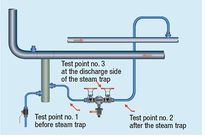
Figure 10. The three test points shown here are used to establish a baseline for ultrasound testing
Setup and operation
The ultrasound unit needs to be set at 25 kHz to provide the highest clarity for high-frequency ultrasound generated by steam or condensate passing through an orifice in a steam trap. The following steps outline a typical operation procedure:
- Pull the trigger to turn on the ultrasound unit. If the instrument is within sensitivity range, the decibel (dB) indicator (A in Figure 11) will blink.
- The decibel reading should be set to 20 dB.
- The kHz (frequency) indicator must be steady and not blinking (B in Figure 11). If the kHz is blinking, then it is in the adjustment mode for frequency. Adjust it to the correct frequency level and push in the sensitivity knob to return to the sensitivity adjustment-setting mode.
- Once in the sensitivity mode, turn the sensitivity control dial clockwise to increase the sensitivity and counterclockwise to decrease the sensitivity.
- The sensitivity control dial increases or decreases the sensitivity of the instrument simultaneously with the sound level in the headphones (NOTE: The instrument needs to be in range for accurate testing).
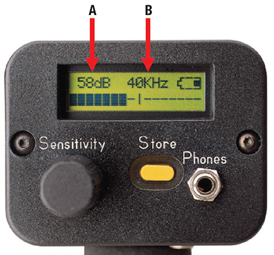
Figure 11. Shown here is a dial reading of a typical ultrasound unit
Testing methods and results
What follows are a few examples of some tests for comparison.
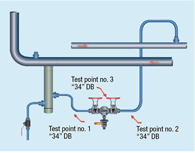
Figure 12. In this example, the ultrasound levels at Test point 3 are equal or less than Test points 1 or 2
Proper Operation (PO). Using Figure 12 as a guide, consider the following three measurements:
Test point 1: 32 dB
Test point 2: 34 dB
Test point 3: 34 dB
If a steam trap is operating properly, the ultrasound level at Test point 3 will not be higher than at Test points 1 or 2.
NOTE: The reading at Test point 3 will be equal or less than the readings at Test points 1 or 2. The high-frequency ultrasound readings, in addition to a temperature measurement that is appropriate for the system pressure, will indicate a properly operating steam trap.
NOTE: If the ultrasound reading at Test point 3 is higher than the readings at Test points 1 or 2, wait for 45 seconds to ensure that the steam trap was not in a cycle mode. During the cycle mode, the ultrasound reading at Test point 3 will be higher, which is the proper operation of a steam trap with on/off discharge cycle.
Float and thermostatic steam traps: Four test points. The float and thermostatic steam trap has two orifices: one orifice for discharging the condensate and the other orifice for the air vent mechanism that discharges air and noncondensable gases.
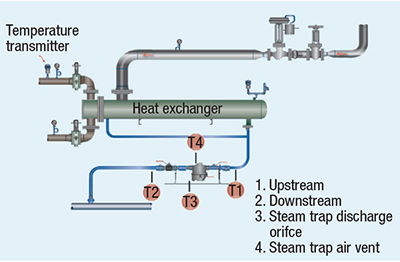
Figure 13. The four test points shown here are used for testing float and thermostatic steam traps
The four test points, shown in Figure 13, are as follows:
T1 — upstream of the steam trap station,
T2 — downstream of the steam trap station,
T3 — at the discharge side of the steam trap condensate orifice, and
T4 — at the discharge side of the steam trap air vent.
NOTE: If the air vent is operating properly, the ultrasonic level at Test point 4 (T4) should be equal to or less than Test point 3 (T3). If T4 is higher than T3, then the air vent mechanism has failed.
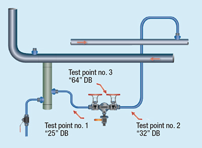
Figure 14. Measurements at three test points indicating a failed steam trap
Blowing or completely failed steam trap (BLW). For this example, the three test points indicated on Figure 14, are as follows:
Test point 1: 25 dB
Test point 2: 32 dB
Test point 3: 64 dB
A significant increase (greater than two times the base level reading) in the decibel level at test point 3 indicates that the steam trap is failed open and allowing steam to pass. Continue to monitor the steam trap at test point 3 to see whether the steam trap cycles according to its design.
Steam leakage.When a steam trap system is leaking steam, the following test points, shown in Figure 15, should be considered:
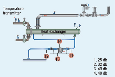
Figure 15. Measurements at these four test points indicate a steam trap leaking steam
Test point 1: 25 dB
Test point 2: 32 dB
Test point 3: 49 dB
Test point 4: 40 dB
An increase in the decibel level at Test point 3 indicates leaking steam through the steam trap. Again, if this increase is observed, take additional time at test point 3 to determine whether the steam trap is in the middle of a discharge cycle. If the decibel level at Test point 3 does not return to the baseline value established at test point 1, then the steam trap is leaking steam.
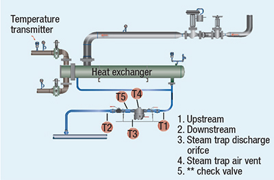
Figure 16. Ultrasound testing of all steam components requires these five test points
Competing downstream ultrasounds. Consider the five test-point measurements shown in Figure 16, in which all the steam components are tested:
Test point 1: 22 dB
Test point 2: 42 dB
Test point 3: 28 dB
Test point 4: 28 dB
Test point 5: 52 dB
The above readings show that ultrasound is being produced downstream of the steam trap. Check valves can be a source of additional ultrasound in the piping system. Perform further testing at the other components in the steam trap station (Test point 5) if the assessor determines that the check valve in the system is generating the high ultrasound levels. If the decibel value is higher at Test point 5, then there are competing ultrasounds in the system. If the value is lower at Test point 5, conduct further examination of the piping and steam trap to determine the source of the higher ultrasound.
Sound characteristics
While using ultrasound listening devices, the tester should be made aware of a few distinct sounds that he or she may hear while testing steam traps:
- Crackling — This sound signature is generated by condensate flowing through a steam trap with flash steam occurring after the discharge orifice of the steam trap
- Whistling — A whistling sound is a characteristic of steam passing through a steam trap orifice
Edited by Gerald Ondrey
Author
 Kelly Paffel is the technical manager at steam-engineering firm Inveno Engineering, LLC (7320 East Fletcher Ave, Tampa, FL 33637; Phone: 239-289-3667; Website: www.invenoeng.com; Email: [email protected]). Paffel has 42 years of experience in steam and power operations, and is an experienced lecturer who has published many technical papers on the topics of steam system design and operation. He is known for writing “Steam System Best Practices,” which are used by plants and engineers globally to ensure proper operation of steam and condensate systems.