In low-flow applications, Coriolis mass-flow controllers can be susceptible to clogging due to their small orifice. Filtration can solve most common clogging issues. Here are tips for filtration and clog prevention
Advanced material and catalyst research, as well as critical dosing and additive applications in the chemical process industries (CPI) require precise, accurate and reliable measurement and control of critical process-fluid flows. Manufacturers need low-flow liquid mass flow controllers that deliver repeatable results to ensure the exact amount of fluid is delivered.
For many low-flow liquid applications, Coriolis-type flowmeters and flow controllers provide superior accuracy independent of fluid properties, such as density or viscosity. However, even the most precisely engineered instruments can deliver faulty or unreliable results if there are fluid contamination and poor filtration preceding the Coriolis flowmeter or controller.
Understanding the sources of clogs and contamination in low-flow liquid-delivery systems, as well as proper filtration systems and techniques can help sustain accuracy and control in these applications.
Coriolis mass-flow measurement
A Coriolis-type flowmeter (Figure 1) is the only type of mass flow measurement and control device currently available that provides a direct mass-flow measurement. Its unique measurement principle is the foundation of Coriolis flowmeter accuracy: A direct mass-flow measurement occurs when a flow sensor device measures the mass flowrate of the fluid without needing to capture or measure additional fluid properties and incorporate those properties into the flowrate calculation.
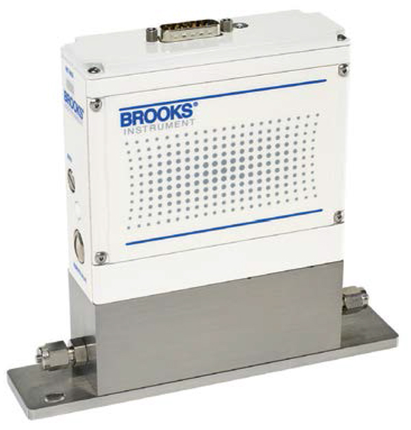
FIGURE 1. In laboratory research and pilot plants, Coriolis mass flowmeters and controllers enable precise measurement of gas or liquid flowrates into a reactor and then the flow measurement of reactor output, to confirm the mass balance and optimize the process
There are several applications in chemical and petrochemical research, pilot-plant development and production manufacturing where direct flow measurement can help achieve superior results. In laboratory research and pilot plants, Coriolis mass flowmeters and controllers enable precise measurement of gas or liquid flowrates into a reactor and then the flow measurement of reactor output, to confirm the mass balance and optimize the process.
In production environments, these devices are used for precise ratio dosing of additives such as corrosion inhibitors or anti-foaming agents into the main process flow. Other applications include deposition of critical materials in fiber optic production, metal coating, glass coating and semiconductor wafer processing.
Contaminant sources, types of clogs
It is important to understand the different types of clogs and contaminants that can develop in liquid-delivery systems, their sources and how those contaminants can clog and disrupt the operation of low-flow liquid measuring and controlling instrumentation.
Solid particulate matter is a contaminant that can pass through any opening greater than the particle’s dimension. A spherical particle with diameter d will pass through any opening greater than d. For rod-shaped particles with diameter d and length l, where l > d, the particles will align themselves with the flow direction, so the characteristic dimension of the rod is still d.
Particle dimensions are usually measured in micrometers (microns;µm). A filter with a cutoff of 1µm will allow particles with a size of 1µm or less to pass through.
One of the most common types of solid contaminant comes from Teflon tape used to seal pipe joints. An easy way to eliminate this from a system is to use a flanged pipe seal instead of threaded connections. However, particles can also be introduced when one part of a system — such as an elastomeric O-ring or seal — comes in contact with a solvent that deteriorates the seal and introduces particles that can degrade meter performance.
Another common contaminant is moisture, which often comes from air that is already in the system. Many chemicals react with moisture to form solid deposits on surfaces or sticky gelatinous substances, leading to clogging.
Aqueous-based fluids that come in contact with bacteria deposited on surfaces exposed to air can also be a persistent source of clogs. Once water is flushed over this surface, the bacteria will pass through the system. When the system is shut down, bacteria will migrate to any carbon source and initiate a bacteria colony (biofilm). When the process flow resumes, the bacteria remains if not properly sanitized, and whenever there is no flow in the system, the bacteria grows until it clogs openings downstream.
While bleach-type additives in the fluid will kill the bacteria, they may not remove it from the surface. The only effective means of dealing with bacteria is filtration. An individual bacterial cell can be treated as a solid particle with a characteristic dimension of 0.45µm. Most filter manufacturers suggest the use of a filter with a 0.2-µm cutoff.
There are two common locations for clogs: filters and valves. Filters can prevent some clogs, but depending on the contaminant’s characteristics and diameter, the material may pass through.
The next location for a clog to occur is in the valve. Valves typically can clog in two ways. If the valve orifice is filled with material, it prevents the controller from achieving full-scale flow (Figure 2). The other way is when material is deposited on the orifice land and is sandwiched between the orifice land and the valve seat. This prevents the controller from fully closing or prevents the valve from controlling below certain flowrates. These two examples actually occur together in most cases.
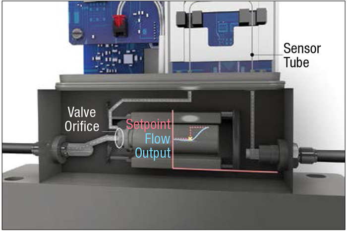
FIGURE 2. Shown here is a cutaway diagram of a Coriolis mass-flow controller. If the valve orifice becomes filled with material, the controller will no longer be able to achieve fullscale flow
Proper filtration
In any fluid system with conditions that risk contaminants and clog formation, filtration is the most effective way to remove solid particulate matter from a fluid. Clogs in filters and valves do more than just disrupt Coriolis device performance and precise low-flow fluid control. Equally hazardous, particles that pass through a controller eventually wind up in the production process, such as in a coating application or a chemical reactor. This will impact the final quality by deteriorating the performance of the manufactured product.
The goal of a filter is to trap these particles before they cause any interruption in either the process (clogging a valve orifice) or the final product (contamination in a coating). Once the particles have been trapped in the filter, the filter is to be discarded and then replaced with a fresh filter.
The best way to determine if the filter is trapping particulate matter is to monitor its pressure drop. When the pressure drop begins to rise, the paths in the filter are becoming blocked, preventing flow of fluids.
All flow controllers must have at least one filter upstream (except in very rare circumstances). The filter traps the particles that would otherwise clog the orifice. In particularly dirty liquid applications, prefilters are common and highly recommended (Figure 3). With some exceptions, prefilters have larger pore sizes. Some Coriolis flow controllers have a 50-µm prefilter preceding an inline filter of 10µm. This allows the prefilter to catch the biggest particles (> 50µm) and greatly extends the life of the inline filter.
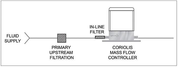
FIGURE 3. In particularly dirty liquid applications, prefilters are common and highly recommended
Detection of clogs
The most common way to detect a clog is when the Coriolis flow controller cannot achieve the desired set point or reliably sustain a targeted flowrate, or when the controller cannot stop the flow.
However, a controller’s inability to reach its setpoint may also be due to a lack of a proper inlet pressure. Therefore, before concluding that there is a clog, one should first confirm that the inlet pressure is sufficient.
In the event of a clog, the filter should be replaced (not simply removed). If the controller can now achieve set point, then the filter caught the clog, and it was time to replace the filter.
However, if the problem recurs a short time later and the controller again cannot achieve set point, it makes sense to filter the process fluid exiting the system with filter paper and inspect it under a microscope for particles. If particles are discovered after passing through prefilters, inline filters and the Coriolis flow controller, the process fluid should be further analyzed. Many liquids react chemically with the moisture found in air. The products of these reactions can then clog either the filter or the valve.
If the filter is not clogged but the controller cannot reach the established process set point, that indicates that the clog occurred after the filter. This is characteristic of clogs caused by a chemical reaction or O-ring/seal degradation. Check the controller documentation and the fluid’s material safety data sheet to assess possible reactions with moisture, as well as to confirm whether the process liquids being transported are compatible with the seal materials and will not swell with the fluid. This is most common with elastomer O-rings and common solvents like toluene, tetrahydrofuran (THF), acetone and similar solvents.
Filter, orifice & particle sizes
Effective particle filtration requires an understanding of filter pore sizes and their relation to the size of particles and orifices in Coriolis flowmeters and controllers. Filters are typically categorized by the maximum size of particle that can pass through it, as measured in microns. Inline filters are typically offered in dimensions of 1, 10, 20, 30 or 40µm.
Let’s compare this to an orifice inside the valve of a low-flow Coriolis mass flow controller. The smallest orifice offered in this industry has an internal diameter (ID) of 0.001 in. This means that the orifice has an ID of 25.4µm, which is much larger than the largest particle that passes through the 1-µm filter. Table 1 compares the filter, orifice and particle dimensions for a typical low-flow Coriolis mass flow controller application.
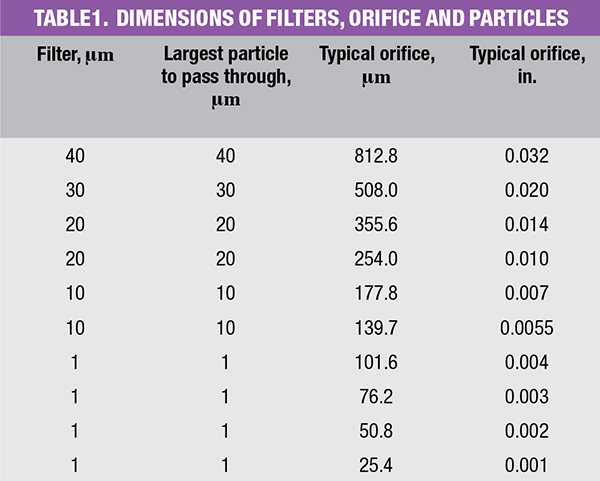
It is recommended that all orifices smaller than 0.007 in. use at least a 10-µm filter. The worst-case scenario would then be to use a 40-µm filter with a 0.01-in. orifice diameter ( D) (254.0µm). The ratio of the orifice diameter to the largest particle to pass through the filter would be 254.0/40 = 6.35. In other words, it would require more than six particles to jam into the orifice before the orifice would clog in one axis. However, the orifice is a hole with an area of π( D/2) 2 = π(254.0/2) 2 = 50,670.7µm 2. Now the area occupied by the particle is π(40/2) 2 = 1256.6µm 2. To completely block the orifice, there would need to be 50,670.7/1,256.6 = 40 particles jammed into it.
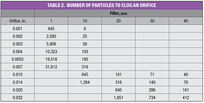
Table 2 shows the calculations of the number of particles that could pass through a given filter to completely clog the area of an orifice. It should be noted that these calculations are estimates of the number of particles needed to clog an orifice. They simply compare the area of the orifice to the area occupied by a particle with a circular area. To be more precise, another term would have to be added to the equation to account for the packing efficiency, as shown in Figure 4. The white area in Figure 4 cannot be filled with the circles. So, the packing efficiency is less than 1. However, due to particle bridging across the orifice, the calculation becomes much more complicated. The numbers in Table 3 are simply presented to promote the understanding of the dimensions involved and are a close-enough approximation to communicate the information.
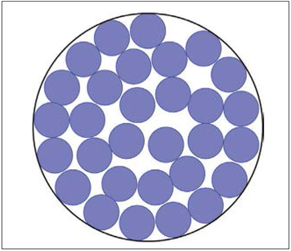
FIGURE 4. When calculating the number of particles leading to a clog, the packing efficiency would also need to be taken into account
These calculations show that use of the appropriate size filter should, in almost all cases, prevent clogging of the valve orifice from solid particles. When clogging issues persist, plant and system operators should focus on other sources of clogging, such as chemical reactions with moisture or compatibility with O-rings.
Startup and shutdown
Many liquids are chemically reactive with water due to the polar nature of water. The most likely source of water in a flow system would be from the atmosphere (relative humidity). Therefore, to properly deliver these fluids, all moisture must be removed from the system. The rate at which these fluids react is dependent on the chemical nature of the fluid and the amount of moisture available for the reaction.
For low-flow Coriolis mass-flow controllers, it is important to understand that the controller is simply a valve designed to manage fluid flow. Once integrated into a system, the control valve orifice will always be the smallest opening the fluid will pass through. This makes it the most sensitive component to a fluid that has begun chemically reacting with moisture and potentially creating contaminants. In the event that the chemical reaction has begun but the contaminant passes through the controller, this material will end up in the final product, reducing yields and product performance.
There are two critical points during system operation when moisture can come in contact with the fluid: at startup and after shutdown. Preventing moisture from entering the system and setting the conditions for the creation of clogs depends on the specific conditions of the plant, how the system is constructed to deliver fluids and the vast array of fluids that might be transported.
At startup, the most practical way to remove moisture is to pull a vacuum to such a level as to remove the air in the system and evaporate all the moisture attached to surfaces in the system. Any small opening will restrict the vacuum pump’s ability to pull the system down (of course, the entire system must be open, so the valve in the controller must be open).
Once the entire system is at a pressure below the vapor pressure of water, it will begin to evaporate. The system is not completely dry until the pressure of the system is stable. To determine this, the system is to be closed and the vacuum pump turned off. The pressure should be monitored for a period of time. If the pressure begins to increase, then either there is a leak or all the water has not yet evaporated. Either way, the system may not be dry enough for some fluids.
Since water will attach to any surface, and small openings limit the ability of the moisture to be removed from the system, filters must be carefully thought out. A filter has many small openings and far more surface area than the tubing or pipes in the system, so far more moisture can be contained within the filter than anywhere else in the system.
Pulling a vacuum on a filter may never completely remove the moisture. If the fluid is reasonably free of solid particulate matter, it may be advantageous to remove the filter from the system. Removing the filter from the system makes it more likely that all the moisture and the source of clogging will be removed.
Edited by Gerald Ondrey
All figures courtesy of Brooks Instrument
Author
 Steve Kannengieszer is a global marketing director with Brooks Instrument (407 West Vine St., Hatfield, PA 19440-0903; Phone: 215-362-3608; Email: brooksam@brooksInstrument.com), focused on mass flow controllers for a variety of industrial markets. He has more than 34 years of experience in product development and management of instrumentation. Kannengieszer has a B.S.M.E degree from Drexel University and an M.B.A from Temple University.