This pictorial guide illustrates some of the common problems that can occur with polymeric and elastomeric materials that differ from those that occur with metallic seals and components
Failures of polymer (plastic and elastomeric) parts and their consequences can be as significant as those of metallic equipment. The information presented introduces some characteristics of polymer parts that impact the equipment that is used at industrial sites. The information covers some aged O-rings, lined pipe, fiber-reinforced plastic (FRP), and pipelines with liners. Characteristics such as permeation, glass temperature, and viscoelasticity are discussed, along with examples of their consequences.
Background
The Space Shuttle Challenger disaster on January 28, 1986, shocked the world. The explosion was due to the O-rings not being able to seal.
The malfunctions described in this article introduce some characteristics of nonmetallic failures that impact equipment used at industrial sites. For each case, important polymer properties are discussed.
Elastomer O-ring failures
Elastomers have glass transition temperatures, which are defined as “the temperature at which an amorphous material (such as glass or a polymer) changes from a brittle vitreous state to a plastic state” [1].
Elastomers have a compression set — this is “reported as the percent of deflection by which the elastomer fails to recover after a fixed time under specified squeeze and temperature” [2]. In the author’s words, the compression set is the rubber’s ability to spring back to its original shape. In many services, the compression set is offset by some of the swelling that develops in service. However, as exemplified below, this is not always the case.
Failure 1. The low 36ºF ambient temperature before launching resulted in the Challenger Space Shuttle’s Viton O-rings being inadequate. As stated in various accident investigations, “Below 50°F, Viton V747-75 O-rings were insufficiently resilient to track the test gap opening” [3]. The glass transition temperature resulted in the Challenger O-rings not being able to seal.
This property impacts seals during low-temperature start-ups — even flare stacks.
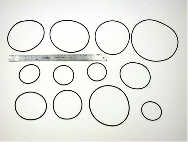
Figure 1. Shown here are O-rings after being used in steam service
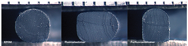
Figure 2. These images show cross sections of O-rings after being used in steam service
Failure 2. The seals shown in Figures 1 and 2 were exposed mainly to water and steam. The site from which the seals were taken had been using ethylene propylene diene terpolymer (EPDM). However, they were testing fluoroelastomer (FKM), such as Viton) and perfluoroelastomer (FFKM), such as Kalrez O-rings. Despite the differences in size, all of the O-rings shown in Figure 2 initially were of the same size:
- The EPDM retained its shape
- The FKM developed an extensive compression set — it did not spring back and may not have sealed the gap between metallic parts when the operating conditions changed
- The FFKM stopped being round, and it also expanded significantly. The expansion of the perfluoroelastomer resulted in parts of the O-ring protruding from their seat. The protrusion, in turn, resulted in the damage shown in Figure 3.
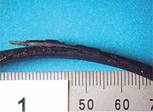
Figure 3. This perfluoroelastomer suffered damage after steam service
What happened? Steam service is challenging for elastomers. For steam service at temperatures greater than 250ºF, gland design calculations considering the expansion of FKM and FFKM and their compression set are needed. Various elastomers have specific advantages and disadvantages — even those with high chemical resistance. Any change requires meticulous care.
General notes on elastomers. In general, for elastomers, service at temperatures greater than 250ºF and temperatures below 35ºF is specialized, and may require a designer’s input.
Identifying the elastomer compounds used is important. Fourier-transform infrared spectroscopy (FTIR) allows one to distinguish between significantly different types of elastomers, such as the EPDM, FKM and FFKM described above. However, examinations to differentiate between one FKM compound and another can be challenging. O-rings made by different manufacturers can have different fillers, curing and processing. All of these have significant effects on the compression set, chemical resistance and low-temperature performance.
Lined-pipe failures
Polymers have long repeating chains of molecules, which allow some fluids to permeate through them. Unlike metals with their crystalline structures, the long molecules become entangled with each other, much like a single strand of cooked spaghetti. Physically very small molecules, such as water/water vapor and gases, can permeate. Some molecules are sufficiently small to pass through the gaps between individual chains.
Failure 3. Typically, the documentation of a failure-analysis investigation starts with images of the parts as received. However, a flat, pliable gasoline-reeking piece of plastic received on a Friday had altered by Monday (when the photos were to be taken) into a rigid and round piece of pipe. Reportedly, the part had been a polyethylene (PE) pipe sheath protecting electrical components below the ground level in a gasoline station. The flat pliable piece of plastic received could not have protected the cables. Gasoline permeation had resulted in a physical, not a chemical change — the PE pipe had not degraded. Nevertheless, a pipe with less permeation softening was needed.
Failure 4. Many industrial sites use Teflon-lined steel pipe for water processing, acid processing, and applications where metal contaminants cannot be present (such as in the food industry). Teflon-lined pipe has vents that allow permeated water on the annular space between the steel and the liner to exit. Nevertheless, after long service periods, the lined pipe has a “best before date.”
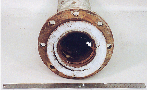
Figure 4. A failed Teflon-lined pipe is shown here after more than 10 years of HCl service
Figure 4 shows a Teflon-lined pipe used in HCl service for more than ten years. Voluminous steel-corrosion products had accumulated in the annular space between the liner and the steel pipe. The products pushed the liner inward, causing damage, as shown in Figure 5. Steel corrosion continued until the pipe leaked.
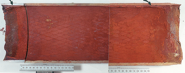
Figure 5. Shown here is the steel surrounding the failed Teflon-lined pipe of Figure 4
Also, the flanged Teflon surfaces had been subjected to creep. Creep is defined as strain (distortion) under constant load. As is the case with metals, creep in polymers increases with increasing temperature. However, unlike steel, creep occurs at room temperature. Likely, as the flanged surfaces’ cross-section had decreased, the steel pipe bolts were retightened until the circular crack shown in the photos developed. The circular crack further exposed the steel pipe to HCl.
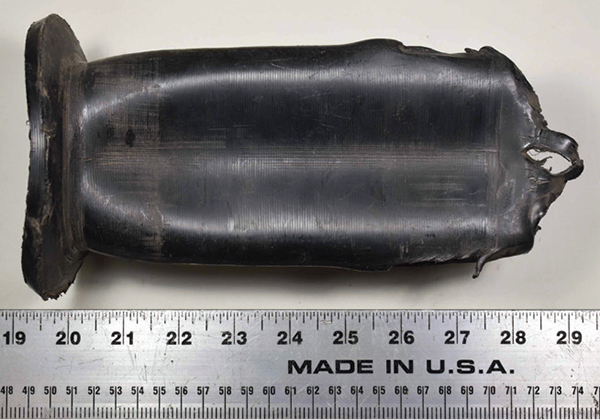
Figure 6. This photo shows an HDPE liner that has collapsed
Failure 5. The upstream oil-and-gas industry uses high-density polyethylene (HDPE) liners commonly to refurbish pitted steel water-injection lines. However, the depressurization of liners has specific management requirements. Figures 6 and 7 show failed liners. The liner single-lobe damage develops as the annular pressure becomes greater than the internal service pressure — the liners collapse due to permeation. For HDPE liners, the best measure to prevent this failure is to avoid rapidly depressurizing the lines.
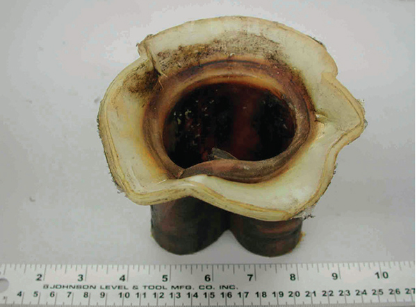
Figure 7. Another view of a collapsed HDPE liner is shown here
FRP failure due to cyclic service
The strength of FRP parts is reduced by cyclic service. As service progresses, the multiple layers can delaminate and crack. API 15 HR, “High-pressure Fiberglass Line Pipe,” has a statement about 20% pressure variations being a limit for testing and service. Canadian standard CSA Z662 “Oil and gas pipeline systems” Clause 13.1.2.8, states that pressure swings need to be kept below 20% of the pipe manufacturer’s pressure rating. Otherwise, the design pressure can be reduced by up to 50%. Lined FRP and FRP requires cyclic loading to be considered during design.
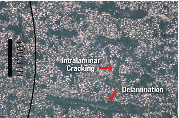
Figure 8. This is a transverse cross-section of failed fiberglass in HDPE-lined fiberglass pipe.
Failure 6. A fiberglass (FRP) pipe used in saltwater service was lined with HDPE along its bottom (6 o’clock) side. The failed section, a non-failed section downstream of the failure, and a third piece (representing an as-fabricated piece) were examined. Specifically, transverse cross-sections of the failed area were compared to those of an as-fabricated pipe of the same size (see Figures 8 and 9). Note the extensive intralaminar cracking in the failed cross-section in contrast to its absence in the as-fabricated pipe. Both the new and failed pipe had delaminations. Delaminations are common in FRP with high glass content; the high glass content confers higher strengths. The pipe had been subjected to severe pressure swings (greater than 20%), and it failed due to cyclic loading.
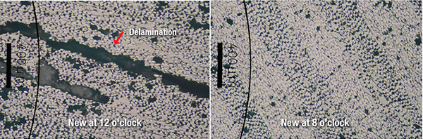
Figure 9. Here are two additional transverse cross-sections of as-fabricated fiberglass in HDPE-lined fiberglass pipe
FRP installation errors
During site installation, smaller sections of pipe are joined — these joints are critical. Typically, two pipe sections are butted against each other, and the gap between the pipe is filled with a “putty.” Then, the joint is wrapped with wide multiple plies of FRP reinforcement saturated with resin. The joint must have adequate reinforcement coverage along the outside surfaces.
Nonmetallic materials, such as the liner and FRP, are viscoelastic. While the characteristic can be challenging to explain, its evidence is common to find — often, damage is introduced during installation, but the leak does not develop immediately. “Viscoelasticity is the property of materials that exhibit both viscous and elastic characteristics when undergoing deformation. Viscous materials, like honey, resist shear flow and strain linearly with time when a stress is applied. Elastic materials (such as steel) strain instantaneously when stretched and just as quickly return to their original state once the stress is removed. Viscoelastic materials have elements of both of these properties and, as such, exhibit time-dependent strain. Whereas elasticity is usually the result of bond stretching along crystallographic planes in an ordered solid, viscosity is the result of the diffusion of atoms or molecules inside an amorphous material” [4].
FRP and plastic parts require exceptional care during installation and handling. Otherwise, they can crack, and the damage may not be evident until much after a hydrotest.
Most lined FRP failures develop because of installation damage [5]. Hydrostatic tests are essential but may not detect small damage that can grow in service.
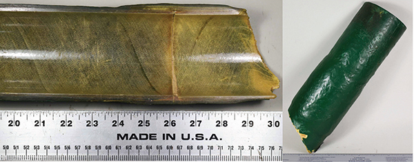
Figure 10. Shown here are the inside (left) and outside (right) surfaces of a joint between FRP pipe sections
Failure 7. Figure 10 shows a joint between two FRP pipe sections. Figure 11 shows a cross-section of the joint. The external reinforcement and coverage along the pipe were insufficient, and the pipe cracked during handling. Guidelines for the reinforcements of joints are given in DIN 16966, CSA Z662, and ASME NM.2.
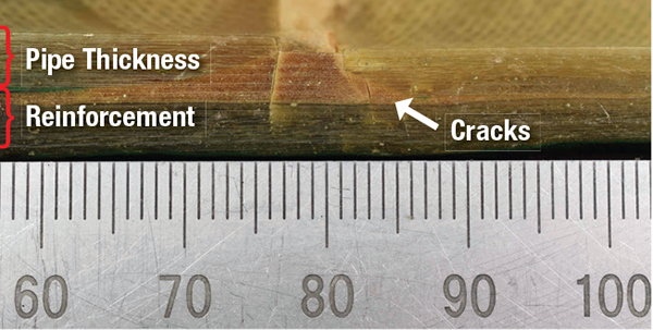
Figure 11. A cross section of a joint between FRP pipe sections is shown here
Slow crack growth in HDPE pipe
HDPE piping is light-weight, corrosion-resistant, and it is commonly used to fabricate gas mains and water lines — including fire water lines at plant sites. Most failures of these lines are due to excavation damage [6]. However, slow crack growth (SCG) failures also develop at relatively low stresses and with minimal deformation. Reportedly, “SCG is a common failure mode in underground polyethylene (PE) piping that was designed for 50-year services” [7].
Failure 8. A fire water line developed SCG after more than 20 years of service. Its fracture had the following characteristics:
- Developed where a tee branch intersected the main run
- Had concentric parallel and rachet marks radiating from the inner diameter (ID) surface
The fracture appearance was characteristic of SCG failures — it had minimal deformation and an origin with multiple concentric rings. Once the SCG region grew to ~2 in. by 1.5 in., rapid crack growth with less visible macroscopic features ensued (Figures 12 to 14). The line had been exposed weekly to load variations greater than 10%. Reportedly, newer HDPE compounds are more resistant to failure due to load fluctuations than the older ones [8]. Nevertheless, operating plants should consider the potential for SCG as HDPE fire water lines age.
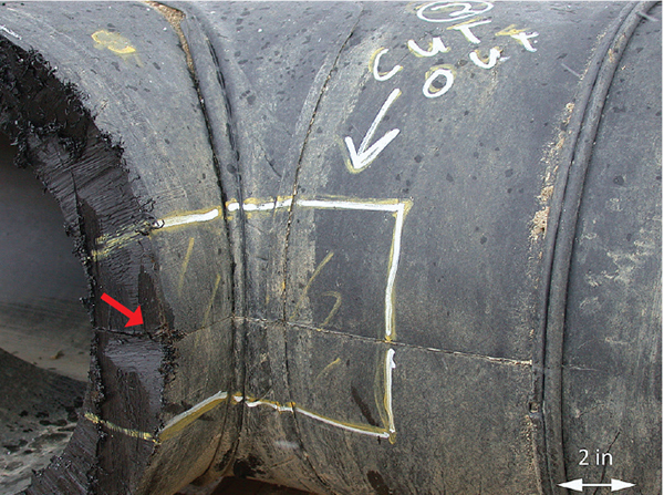
Figure 12. In this photo, one can see the intersection from a tee branch to the main run, which developed the crack pointed at with a red arrow
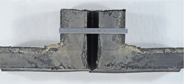
Figure 13. This cutaway shows the fracture surface of the tee branch to tee main run
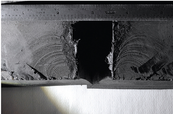
Figure 14. A closer view of the fracture surface of the tee branch to tee main run is seen here. Crack initiation is apparent on the inside surface
Handling of HDPE containers
Intermediate bulk containers (IBCs) are practical for storing and shipping small amounts of chemicals (Figure 15). They are so dependable that it is easy to forget that their failures pose significant hazards. However, IBC failures can result in significant economic losses — the author has investigated a couple of them. Most of the failures result from mishandling [9–11]. While IBCs appear to be simple to examine, HDPE cracks from mishandling can be difficult to see. For the asset management personnel in companies that use IBCs containing hazardous products routinely, careful periodic external and internal inspections are necessary — they are mandatory in the U.S.
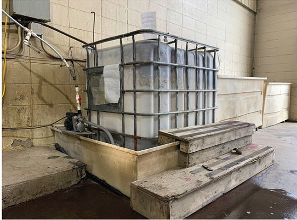
Figure 15. Shown here is a typical storage intermediate-bulk container
UV exposure damage and aging
Ultraviolet (UV) damage and aging are ubiquitous in polymers. This means that we must carefully follow O-ring storage instructions and consider the life implications for outdoor components such as liners of open-top tanks and ponds. While we need to optimize (minimize) maintenance budgets, some inspections are necessary in outdoor components, especially those exposed to sunlight (Figure 16).
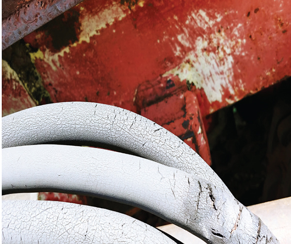
Figure 16. These cable sheaths have been damaged due to exposure to ultraviolet radiation and aging
Final remarks
Characteristics such as the glass transition temperature, compression set, permeation, creep at room temperature, viscoelasticity, slow crack growth, and others determine plastic and elastomeric parts’ service performance. For critical components, these characteristics must be considered to obtain an efficient and effective service for which polymers should be known.
Acknowledgments
The author would like to thank the understanding customers and colleagues who shared their findings with the industry.
Edited by Gerald Ondrey
References
1. Lewis, Sr., Richard J., “Hawley’s Condensed Chemical Dictionary,” 12th ed., International Thomas Publishing, London, U.K., 1992.
2. Online source: https://promo.parker.com/promotionsite/oring-ehandbook/us/en/ehome/laboratory-compression-set.
3. Lach, Cynthia L., Effects of Temperature and O-Ring Gland Finish on Sealing Ability of Viton V747-75. NASA Technical Paper 3391, 1993, https://ntrs.nasa.gov/archive/nasa/casi.ntrs.nasa.gov/19940013602.pdf.
4. Online source: https://altis.world/glossary/viscoelastic.
5. Canada’s Oil and Natural Gas Producers (CAPP) Best Management Practice, “Use of Reinforced Composite Pipe (Non-Metallic) Pipelines,” April, 2017.
6. Maupin, J., and Mamoun, M., Plastic Pipe Failure, Risk and Threat Analysis, DOT Project No. 194, 2009.
7. Xiangpeng Luo, Jianfeng Shi and Jinyang Zheng, Mechanism of Slow Crack Growth in Polyethylene: A Finite Element Approach, ASME 2015 Pressure Vessels and Piping Conference, Boston, Mass., 2015.
8. Oliphant, K., Conrad, M. and Bryce, W., Fatigue of Plastic Water Pipe: A Technical Review with Recommendations for PE4710 Pipe Design Fatigue, Technical Report of behalf of the Plastic Pipe Institute, May 2012.
9. CBA/SIA Guidance for the Storage of Liquids in Intermediate Bulk Containers, ICB Issue 2, October 2018. Online: www.chemical.org.uk/wp-content/uploads/2018/11/ibc-guidance-issue-2-2018-1.pdf.
10. Beale, Christopher J., Way, Charter, The Causes of IBC Leaks at Chemical Plants — An Analysis of Operating Experience, Symposium Series No. 154, IChemE, Rugby, U.K., 2008, Online: https://www.icheme.org/media/9737/xx-paper-42.pdf.
11. Madden, D., IBC Tote Maintenance: Five Tips to Make Them Last, entry posted in Bulk Containers, IBC Totes, Sustainability, posted in blog.containerexchanger.com, September 15, 2018.
Author
 Ana Benz is the chief engineer at IRISNDT (5311 86th Street, Edmonton, Alberta, Canada T6E 5T8; Phone: 780- 577-4481; Email: [email protected]). She has worked for 24 years as a corrosion, failure and inspection specialist. Her expertise includes inspections and organizing plant inspection projects using advanced inspection technologies. Benz has worked extensively for the chemical process industries, in petrochemical plants, fertilizer plants and nickel refineries around the world, as well as oil-and-gas production sites. She holds a degree in materials engineering from the University Simon Bolivar in Venezuela and also holds an M.S. in materials engineering from the University of British Columbia. She has several Canadian General Standards Board (CGSB) NDT certificates, as well as API 510 certifications and Level 3 certification from the CWB Group. Benz was a member of the NACE Edmonton Executive chapter for 15 years, and before that, participated in various capacities for the Edmonton Chapter of the Canadian Welding Institute.