Improved understanding of the causes of piping leaks can reduce the frequency of leaks and lead to significantly better performance over time
Leakage in pipes is an ongoing problem in research and development facilities across many sectors of the chemical process industries (CPI), such as petrochemicals, pharmaceuticals, food and beverage and others. Leakage can negatively affect operations in pilot plants and laboratory units, and can affect a wide range of laboratory equipment, analytical instruments and testing equipment. Leaks are costly and time-consuming to find, and often are even more expensive to fix. Leaks result in poor-quality data or invalid results, which can require needless rework. Because leaks create unnecessary downtime and program delays, they drain stretched research resources.
Leakage is often ignored or accepted as a “necessary evil.” It is common for scientists and engineers to talk about getting a system “leak tight” as if it is a one-time activity. Yet every system, no matter how well designed or well maintained, is almost certain to leak somewhere at some time. Therefore, leak testing needs to be a routine activity, not a one-time task. Simultaneously, research personnel commonly think of leaks as unfortunate, but inevitable occurrences, like adverse weather conditions — “unfortunate, but what can one do?” As a result of that mindset, few efforts are made to prevent or minimize the frequency of leaks.
Significantly better performance can be achieved over time by (1) understanding the common causes of leaks and (2) taking proactive steps to reduce their frequency. This article focuses on tubing and small-bore piping, which are more common in research and development.
Common causes of leakage
The following items constitute major causes of leakage in piping systems.
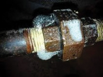
Figure 1. This photo shows a leaking pipe union, probably resulting from being under tightened or forced together during assembly
Improper assembly. Pipe threads are often under-tightened (Figure 1). Undersized wrenches are often used because they are handy or to get more clearance, but this results in the need to exert more force in connecting pipes, which is often not supplied. If upstream and downstream fittings are not properly held, they may slip before the necessary turns have been completed. In order to achieve the desired alignment, fittings are sometimes not tightened all the way. In order to get fittings to match up, they are often tightened insufficiently or forced into place. The former results in a connection that is too loose; the latter produces needless stresses, eventually promoting leaks.
Poorly applied pipe sealant. Pipe sealant is often seen as an area to reduce costs, so inexpensive (and lower-quality) sealants may be used, or sealant material may be applied too lightly. Also, to save time, sealant may be applied unevenly. Tapes are allowed to bunch up due to poor assembly.
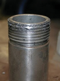
Figure 2. Badly rounded threads like those shown here are almost certain to leak
Badly threaded pipe fittings. Dies for threading pipes are often used well past their lifetimes, resulting in rounded threads that are difficult to seal and are prone to leakage (Figure 2). When standard dies are used to thread high-alloy pipe, they wear out quickly, usually well before anyone realizes there is a problem. Dies are sometimes not started carefully enough, resulting in threads that are not true and are more prone to leaks. Also, pipe threads can be cut too short or too long to make something fit an exact dimension.
Compression fittings are not tightened properly. Pipe fittings are often tightened by “feel” instead of by the number of turns. Worse, many are deliberately under-tightened for longevity. Compression fittings that are routinely removed and replaced will, over time and dozens if not hundreds of cycles, eventually start to leak and need to be replaced. The more the fitting is tightened, the shorter the time until this can happen. Most manufacturers recommend 1¼ turns as a good compromise between longevity and integrity. However, good-quality compression fittings will often seal with fewer turns. So some personnel under-tighten compression fittings routinely to extend their life. But this results in a much greater chance of leakage, as the safety factor inherent in the manufacturer’s recommendations is no longer present.
Tubing inserted improperly. If tubing is not inserted all the way into the fitting and fails to bottom out, this will result in a poor seal.
Debris and scratches. Fitting sealing surfaces and tubing outside surfaces are not generally treated carefully enough. Dirt, grit or foreign materials are often present, albeit in small amounts, but enough to cause gaps or scratches and promote leakage. Poor work practices prevent the fittings or the tubing from staying clean enough. Tubing is often badly scratched from poor handling practices, being dragged along floors, dirt, or other surfaces that produce small scratches that make it more difficult for the system to seal properly. All could be prevented by proper handling techniques.
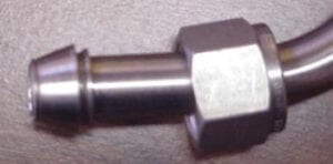
Figure 3. The tubing shown in this photo was probably poorly aligned and felt like it was properly inserted to bottom out in the fitting. It leaked immediately upon startup and the entire piece had to be replaced
Misalignment. Ferrules are left out, damaged, or so badly misaligned that sealing is compromised. Some tubing is not aligned properly (Figure 3). Either it is placed in at an angle or forced into the fitting in such a way that the resulting forces are working against the fitting itself, promoting leakage.
Tubing hardness. For compression fittings to work properly, the ferrules must be harder than the tubing, so they can bite into it (compress) and make a good seal (Figure 4). Thus, every quality manufacturer has a maximum recommended tubing hardness. Sadly, most tubing is bought from local suppliers with no reference to this
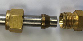
Figure 4. The softer copper ferrule shown in the photo will never seal properly on the harder stainless-steel tubing
property. This often results in tubing that is too hard for a good seal and numerous unnecessary leaks.
Heating and cooling
Routine temperature changes always create more leaks. Whether these are heating or cooling is immaterial. Large (>150°C) or rapid (>25°C/min) temperature swings can cause leakage in as little as one cycle. The author has seen fittings that started out leak-free and properly tightened become less than hand tight at the end of a heating or cooling cycle.
Ambient temperature swings, often routinely ignored, are a significant continuing problem. While slower and of less magnitude, ambient temperature swings happen with a much higher frequency (every day). The frequency more than compensates for the smaller magnitude and greatly promotes leakage. Common problem areas include pipes that are outdoors, in non-air-conditioned process bays, and facilities with significant off-hours temperature changes. Sterilization and cleaning-in-place are often overlooked as a source of the same issue.
Stress and torque
Pipe fittings that are subject to higher stresses and torque tend to leak more easily because these forces work against the sealing surfaces over time. Work on adjacent fittings or components can cause two leaks for each component touched (one on each side). Hold backs, or a wrench or pliers designed to prevent the body of the fitting from moving, are difficult to always coordinate properly. Often, users respond to the turning motion after the stationary fitting starts to move, so it has already been loosened. Other problem areas include equipment, components and pipe sections that are frequently removed. These will leak not only at the disconnect points, but also often at nearby connections. Turning a poorly supported valve increases the potential for the torque to loosen the fitting and cause a leak. Vibrations, bumps and similar shocks from equipment and operations all can contribute to leakage.
Clearance issues
Pipe threads, unions and compression fittings require clearance when connecting and disconnecting to allow components to be removed. It is often difficult to provide sufficient clearance, leading to problems including improper tightening, bent tubing or sprung piping (piping that has been forced together and has significant residual stresses trying to pull it apart). This is often a problem when piping or tubing is deliberately cut short to generate the clearance. In this case, it will tend to spring apart when loosened, allowing for easier removal, but leading to a much higher likelihood of leakage. Flanges and sanitary fittings are commonly pulled apart to make gasket access easier, resulting in stress on nearby fittings. This often results in bending nearby components and increased chance of leakage. Maneuvering to remove a larger, heavier or awkwardly shaped component often results in bumping, banging, leaning on or similarly disturbing adjacent piping and components.
Guidelines to minimize leakage
The following practices will help reduce the likelihood of pipe leakage.
Buy quality components. The adage “you get what you pay for” is very true for pipe and compression fittings. There is a reason why union or connector costs differ drastically from one supplier to the other. Components with lower initial costs will almost invariably turn out to cost more in the end when the costs of finding and repairing leaks are included. Quality always costs more, and many very low-cost fittings are sold primarily on price and are often of poor quality.
Select the proper components for the service. Make sure the tubing you purchase has the proper hardness. Confirm that all the piping components have an adequate pressure and temperature rating with an adequate margin above your highest operating conditions. They need to be suitable for those infrequent times that are hotter or cooler than normal. This is particularly relevant in exterior service, where failing to account for the few days a year above 100°F or below 0°F can create needless problems. Recognize that solar gain (the heat that metals will pick up when exposed to the sun) can be significant (10–30°F). Trying to locate fittings in the shade may help reduce issues but it will only help at best, not eliminate the issue.
Assemble fittings properly. Train all personnel on proper assembly techniques. Leaders should not assume that all personnel know how to assemble fittings correctly, or that they will carefully read the (often cryptic, or missing) instructions. These steps may seem like overkill, but they really do help prevent needless leaks. Gauge compression fittings after assembly to confirm proper makeup. The short time this takes pays rich dividends on showing which fittings need to be tightened. Mark the fitting to indicate the proper number of turns or make sure you have some way to always count them. Make sure the tubing is fully inserted into a compression fitting by either marking the proper insertion depth and making sure it goes in that far or disassembling the fitting to make sure it was done properly. Occasional checks after assembly are often prudent as a quality-control measure. Quality fittings come with the ferrules aligned and the nut just loose enough to insert the tubing. Try to avoid taking them apart before assembly. While perfectly acceptable, it does increase the chances of misalignment and should be avoided if possible.
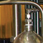
Figure 5. Buying the right fitting would reduce the potential leak points by two, by eliminating the pipe bushing
Consider leakage in the design. Avoid problematic connections, such as pipe threads and pipe unions, particularly in heated or cooled lines or in gas service. Consider where flanges may be a better choice on larger lines and compression fittings on smaller lines (Figure 5). Allow reasonable access to all components and connections, not just the ones you think likely to leak, and particularly those that need higher maintenance. These include: pumps, compressors and similar rotating equipment; filters, purifiers and similar items that need to be cleaned or replaced; and all instrumentation. Some time and effort during the design stage produces much lower leakage rates.
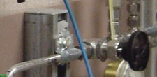
Figure 6. A second support downstream of the valve is necessary to minimize the force from turning the valve
Use holdbacks. Always use a holdback to keep adjacent fittings from being needlessly turned or stressed. Train personnel how to use it properly (Figure 6). This is something that sounds easy until you do it. Support all your valves, or at least all the valves you will turn with any frequency. Individual valve brackets work best, whether homemade or purchased. Supporting valves by clamping the tubing on each side is effective if the supports are close enough. Panel board mounting is not recommended. While it rigidly supports the valves, it is difficult to align all the tubing properly. This leads to frequently forcing it into place with increased risk of leakage. It also makes leak testing harder due to limiting access.
Consider custom fabrications to reduce the number of potential leak points. Waiting a few weeks for a vessel with exactly the ports you need, paying extra for a nonstandard fitting, asking for welded fittings instead of threaded, or specifying an instrument with integral compression fittings instead of adaptors almost always ends up costing less and being faster in the end. It does, however, require some thought during the design and procurement stage.
Minimize the number of joints. Fewer joints mean fewer potential sites for leakage. Bend more tubing instead of using elbow fittings. Use crosses instead of dual tees (four versus six potential leak sites). Purchase reducers that match exactly the sizes you need rather than using multiple fittings. Specifying valves with different inlet and outlet connections, gages with tubing connections, or instruments with tubing connections may cost a bit more and take somewhat longer for delivery, but the savings in time and effort in finding and correcting needless leaks always outweighs these initial outlays. Consider in-house or custom fabricating those things you can’t purchase. Machining specialty fittings, welding two stock fittings together, or getting a custom component manufactured is often feasible. The extra time spent and cost are always recouped quickly through reduced leak testing and locating and remedying leaks found.
Properly mount equipment. Make sure the mounting provides adequate strength to resist the forces that will be applied to it. How often have you seen tubing bent near a cartridge filter that required a wrench to remove or a valve that can be seen to move slightly when it is turned? Substantial-looking brackets can flex in unplanned directions. Often the support for the bracket is too flimsy and flexes. Supporting pipe or tubing to other pipe or tubing is a bad practice. While it can prevent sagging on long runs, it provides little support to prevent leakage.
Pipe removable components properly. Consider how you would assemble and disassemble any component that needs maintenance or changing such as filters, purifiers or traps. How do you remove instruments for calibration or control valves to replace trims? Plan on how you remove them without generating needless leaks. Zero-clearance fittings are well worth the extra cost. Flexible hoses and removable U bends often eliminate or at least reduce needless leakage. This may require extra space during the layout.
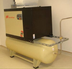
Figure 7. The compressor should have a flexible connection as the fitting on the tank is certain to leak over time
Isolate vibrating equipment with damping pads or springs. Flexible connections to fixed systems, such as compressors, pumps, vacuum pumps and mixers, are important for all piping (Figure 7). Make sure the supporting structure is stiff enough that it does not vibrate or flex during operation. Make sure that any residual vibration is dampened as much as possible. Do not anchor tubing supports to the rotating equipment stand. That usually just transmits the vibration even further.
Carefully design systems subject to temperature changes. Wherever possible, avoid or minimize joints. Instead, use welding, brazing or soldering to eliminate these potential leak points. Utilize specialty fittings and components with fewer joints. Use more leak-resistant components like vacuum fittings. Consider packless valves and similar “sealless” components. Avoid heat tracing if possible and consider small heated enclosures instead. These raise the temperature of all the internal components at a similar rate and minimize leaks due to uneven thermal stresses. Heated enclosures will, unfortunately, still result in piping leaks upon cooling or other temperature changes, but will avoid numerous routine temperature differentials that are always produced by heat-tracing systems. These differentials are certain to increase the number of leaks. The use of heated enclosures also allows modification, leak testing and maintenance without insulation removal and replacement — another cost savings.
Consider keeping the system at a constant temperature when not in service. The extra expense associated with doing so is often more than offset by a reduced leak rate. Provide for gradual heat up or cool down — the slower, the better. Automating the process to slowly ramp up or down over time is often a good way to implement this method. Allow for expansion and contraction, even in shorter runs.
Is it possible to implement all of these suggestions all the time on all your units? Sadly, in the real world, probably not. You likely will not have enough space, money or time to always do everything 100% correctly 100% of the time. But by following these guidelines as much as possible, you can make significant improvements in reducing pipe leakage.
Edited by Scott Jenkins
Author
 Richard Palluzi, PE, CSP, is founder and owner of Richard P. Palluzi LLC (72 Summit Drive, Basking Ridge, NJ 07920; Email: [email protected]; Phone: 1-908-285-3782), a consultancy for the pilot-plant and laboratory research community. Palluzi provides consulting on all aspects of safety and design for pilot plants, laboratories, research facilities and operations. He retired as a distinguished engineering associate after 40 years at ExxonMobil Research and Engineering, where he was involved in the design, construction and support of pilot plants and laboratories for ExxonMobil affiliates worldwide. He is the author of two books, over 100 articles and 40 presentations. Palluzi was chair of the AIChE Pilot Plant Committee, ExxonMobil’s Pilot Plant and Laboratory Safety Standards Committee and ExxonMobil’s Safe Operation Team for its Clinton Facility. He is on the National Fire Protection Association NFPA-45 Fire Protection for Laboratories Using Chemicals and NFPA-55 Industrial and Medical Gases committees. Palluzi also teaches courses for the University of Wisconsin’s Department of Engineering Professional Development, as well as provides customized training to the research community. He holds B.S.Ch.E. and M.S.Ch.E. degrees from Stevens Institute of Technology in Hoboken, N.J.