Don’t panic — What appear to be scratches on a vessel may be an illusion caused by improperly applied LED lighting
Imagine looking into a sight glass for a routine tank inspection, and seeing for the first time numerous scratches and potential points of contamination. What could have happened?
As more operators switch to light-emitting diode (LED) lighting to illuminate the interior surfaces of process vessels, many are often alarmed by the sudden appearance of scratches that appear on the vessel walls. In most cases, these are “false positives” caused by improper application of LED lighting. This article discusses the science behind this phenomenon, and provides guidance on how to properly apply LED lighting to gain a more accurate view of your processes.
Lighting choices

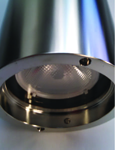
FIGURE 1. A light diffuser may be incorporated into the lens of a sight glass light (Source: L.J. Star)
Many pharmaceutical and biotech companies are switching to LED lighting in their process operations, either as part of a company’s environmentally friendly initiatives, or because of other advantages of LED lighting technology. In general, LED lights bring a variety of advantages. For instance, they have a far longer service life than traditional halogen bulbs, which reduces labor costs. LED lights can also be brighter, and their “color temperature” can be selected for optimal illumination of the process.
Unlike incandescent lights, LEDs emit very little heat compared to infrared light, which means they do not add heat to a process or environment. Finally, LED lights can be computer-controlled, which allows for dimming control.
However, LED lights will not be successful in an application unless they can provide an accurate view of the process. In order to prevent the appearance of insignificantly small scratches and surface features, LED lights used to illuminate process vessels should incorporate a diffuser in the lens.
A diffuser is a device that scatters light. They are commonly made out of translucent objects such as ground glass, Teflon or opal. Diffusers are a simple, affordable solution that can be specified at the time of sight-glass light selection (Figure 1).
For many pharmaceutical processes, some food-and-beverage processes and specialized chemical-process operations, visual inspection is often used to observe the characteristics of the process medium and to verify certain process steps, such as a clean-in-place efforts. Such visual inspections should show smooth, crevice-free surfaces that cannot harbor bacteria or other contaminants.
Halogen lighting — the traditional, filament-based lighting option — has a natural tendency to produce light over a wide area and spread that light in all directions (because filaments illuminate in all directions). Under such diffused light, a highly polished stainless steel vessel has a mirror-like finish.
By contrast, LED lighting emits light from a small area, making the light emit radially outward as if it came from a single point. This radially emitted light is mostly undiffused light, so it reflects off objects more uniformly. Undiffused light will reveal tiny imperfections in the steel surface that are in most cases inconsequential. Figure 2 shows the difference between diffused and undiffused light sources.
To illustrate the different effects of diffused versus undiffused light, Figure 3 shows photos of the same steel surface under diffused and undiffused light. The stainless steel is polished to a pharmaceutical-industry common surface finish Ra (roughness) of less than 20 micro-inches (µin; roughly equivalent to 0.5 micrometers).

FIGURE 2. Halogen lights (left) emit light over a wide area from a diffused source. By contrast, LEDs (right) emit light directionally, from a point source, creating an undiffused light source that tends to illuminate surfaces more uniformly.
Viewed under diffused light (Figure 3a), the stainless steel appears bright and has a mirror-like finish (which presents the impression of a flawless reflection). However, when viewed under undiffused light (Figure 3b), the same steel appears dark and has many apparent scratches.To analyze these results, the color photos can be transformed into grayscale, and then the intensity distribution of the reflected light can be graphed on a histogram (Figure 4). The intensity distribution for the undiffused light is wide, has a long tail, and a lower mean than the intensity distribution for the diffused light. This shows that polished stainless steel reflects diffused light more consistently than undiffused light.

FIGURE 3. Figure 3a (left): A stainless steel surface viewed under diffused light appears pristine. Figure 3b (right): By contrast, the same stainless steel surface, viewed under undiffused light, reveals surface imperfections that may or may not be significant

FIGURE 4. Figure 4a (left): The intensity distribution of diffused light on stainless steel is relatively narrow. Figure 4b (right): By contrast, the intensity distribution of undiffused light on stainless steel is wider
When the images are transformed into a high-contrast (binary) image (Figure 5), the reason for the wide spread in the histogram of the undiffused intensity distribution is related to all of the scratches present in the photograph in Figure 5b. By contrast, the diffused light image (Figure 5a) does not show as much variation (almost none of the binary image is white).

FIGURE 5. The binary image (left) was generated by shining diffused light on stainless steel. The binary image shown on the right was generated from shining undiffused light on stainless steel.
Phong Reflection Model
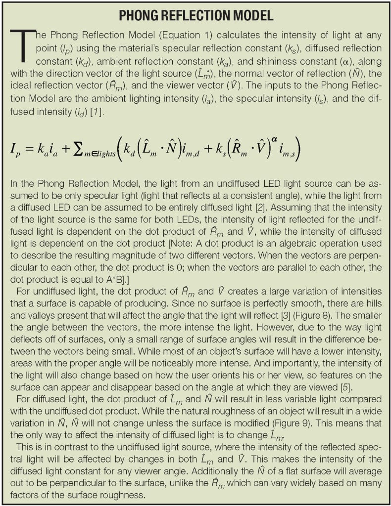
When an optic reflection model — called the Phong Reflection Model (box, p. 56) — is applied, then the mechanism for how undiffused light and diffused light behaves becomes more clear. The Phong Reflection Model is an empirical model for light reflection, which calculates the intensity of light using a number of inputs (see sidebar, below, for details). It is commonly used in reflection calculations for computer rendering [ 1 ].
Because no surface is perfectly smooth — even highly polished stainless steel has tiny hills and valleys on its surface — these imperfections affect the angle at which the light reflects [ 2 ]. The smaller the angle between the vectors, the more intense the reflection. The model predicts that the intensity of the diffused light will be constant for any viewer angle, and that undiffused light will reflect light more intensely in some areas when viewed at certain angles.

FIGURE 8. When spectral light reflects off of an uneven surface the difference between the reflection vector and the viewer vector affects the intensity of the reflected light

FIGURE 9. When diffused light reflects off of an uneven surface, the difference between the light vector and the normal vector affects the intensity of the reflected light
Hard and soft light
The difference between undiffused and diffused light on stainless steel does not end with how the light reflects off the steel. The geometry of the light source also affects the appearance of the steel surface. When the light source does not have an area much greater than the object it is illuminating, then hard light is produced [ 3 ] (Figure 6). The light-producing region of a typical LED is on the order of a square millimeter or less, which is relatively small.
![FIGURE 6. When the source of light is small compared to the illuminated object, the light produced is hard. When the source of light is large compared to the illuminated object, the light produced is soft [4]. Note the differences in the shadow patterns on the subjects](https://www.chemengonline.com/wp-content/uploads/2016/01/63.jpg)
FIGURE 6. When the source of light is small compared to the illuminated object, the light produced is hard. When the source of light is large compared to the illuminated object, the light produced is soft [4]. Note the differences in the shadow patterns on the subjects
When hard light hits an object, shadowing and masking occur [ 4 ] (Figure 7). Both of these phenomena occur because the geometry of the surface being illuminated blocks light from reaching certain areas of the surface (a phenomenon called shadowing; see Figure 7a), or reflects light in such a way that certain regions receive extra ligh, covering certain areas of the surface; this is called masking (see Figure 7b).

FIGURE 7. Figure 7a (left): Shadowing occurs on a rough surface. The light is unable to reach certain areas of the surface. Figure 7b (right): Masking occurs on a rough surface. The light is reflected off the geometry of the surface in such a way that the region will gain increased intensity
By contrast, soft light does not produce shadowing and masking, because the light hits the steel at a variety of angles.
Diffusers have a surface area that is measured in square centimeters, much greater than the imperfections on the surface of the steel, and therefore the light is soft. Soft, diffused light reduces the prominence of surface imperfections of steel through the reduction of both shadowing.
Edited by Suzanne Shelley
References
1. Lyon, Phong, Richard F., Shading Reformulation for Hardware Renderer Simplification, Apple Computer, Inc., accessed on the Web. 29 Sept. 2014 (http://dicklyon.com/tech/Graphics/Phong_TR-Lyon.pdf).
2. Jensen, Henrik W., Marschner, Stephen R., Levoy, Marc, and Hanrahan, Pat. A Practical Model for Subsurface Light Transport. Stanford, accessed on the Web. 29 Sept. 2014 (http://www.cs.berkeley.edu/~ravir/6998/papers/p511-jensen.pdf).
3. Curtin, Dennis P., Understanding Hard and Soft Light Short Courses. Short Courses, 2011, accessed on the Web. 29 Sept. 2014 (http://www.shortcourses.com/tabletop/lighting2-8.html>.
4. He, Xiao D., Torrance, Kenneth E., Sillion, François X., and Greenberg, Donald P., A Comprehensive Physical Model for Light Reflection, ACM SIGGRAPH Computer Graphics, Vol.25.4, pp.175–86, 1991.
5. Phong, Bui Tuong. Illumination for Computer Generated Pictures, Communications of the ACM, Vol. 18.6 (1975): 311–17, 1975.
Author
 David Star is president of L.J. Star, Inc. (P.O. Box 1116, Twinsburg, OH 44087; Phone: 330-405-3040; Email: dstar@ljstar.com). He is an expert in the application of sight-glass technology, light and glass characteristics, and related industry standards.
 Aarash Navabi is a consultant and certified pharmaceutical industry professional (CPIP), a certification accorded by the International Society of Pharmaceutical Engineering (ISPE), which recognizes comprehensive knowledge in the pharmaceutical industry.
 Mathew Hildner is a research and development engineer at L.J. Star, Inc. (same address as above). He holds a B.S. in mechanical engineering from Massachusetts Institute of Technology (MIT).
