Presented here are practical points to help in the selection of plate-and-frame and air-cooled heat exchangers
With a wider variety of heat exchangers to choose from than ever before, there are a number of variables to be considered when assessing options.
As energy-intensive industries increasingly look for ways to improve efficiency, choosing the right heat exchanger to fit the needs of specific applications and systems is critical.
In the second part of this two-part series, we look at specification tips to maximize heat transfer in plate-and-frame and air-cooled style heat exchangers in order to boost heat-exchanger performance and increase efficiency. (For part 1, which covered shell-and-tube heat exchangers, see Chem. Eng. February 2022, pp. 42–44).
Plate-and-frame exchangers
The plate-and-frame heat exchanger has emerged as a viable alternative to shell-and-tube exchangers for many applications. Such units are composed of a series of plates, mounted in a frame and bolted together. Space between adjacent plates form flow channels, and the system is arranged so that hot and cold fluids enter and exit through ports at the four corners (Figures 1 and 2).
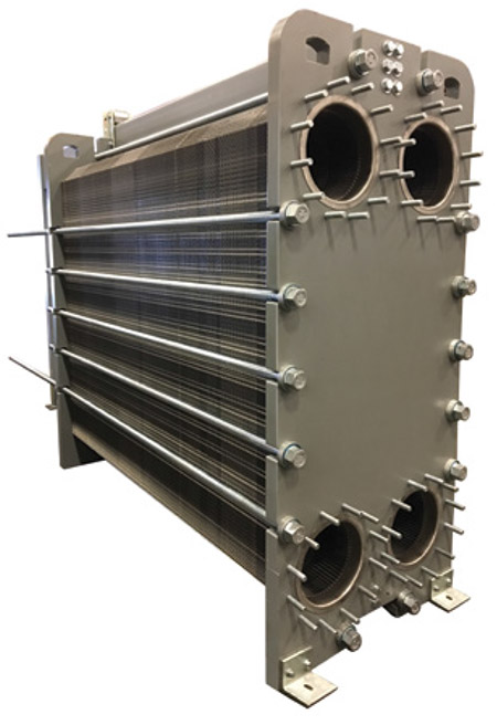
FIGURE 1. When the plates of a plate-and-frame exchanger are assembled, the holes in the corners form a continuous channel. Alternating gasket patterns direct the hot and cold fluids into alternating passes. Heat transfer then takes place across the plates
Within the exchanger, an alternating gasket arrangement diverts the hot and cold fluids from each inlet into an alternating sequence of flow channels. In this arrangement, each cell of heat-transfer media is separated by a thin metal wall, allowing heat to transfer easily from one media to the other.
A corrugated chevron or herringbone pattern is pressed into each plate to give the exchanger strength and rigidity, to extend the effective surface area of plates and to increase turbulence in the flow channels, which combined, boost heat transfer (Figure 2).
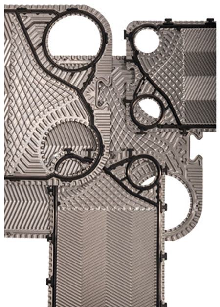
FIGURE 2. A corrugated chevron or herringbone pattern is pressed into each plate to give the exchanger strength and rigidity, to extend the effective surface area of plates and to increase turbulence in the flow channels, which combined, boost heat transfer
The plate and frame’s highly efficient countercurrent flow typically yields heat-transfer coefficients three to five times greater than other types of exchangers. As a result, a more-compact design is possible.
Depending on the applications, plate selection is optimized to yield the fewest total number of channel plates. Because the plates can be easily removed, service and maintenance costs are typically lower than that of shell-and-tube exchangers.
Although the plate-and-frame heat exchanger can be used in a broad range of applications, the following selection criteria may be used as a guideline:
- Maximum design or working pressure is limited to 450 psi
- Temperature limits and fluids must be compatible with gasket materials, typically limited to 300°F
- Plate materials must be compatible with process media
- The narrow passageways in the plate and frame can result in high pressure drops, making the exchanger incompatible with low-pressure, high-volume gas applications
- Rapid fluctuations in steam pressures and temperatures can be detrimental to gasket life. For this reason, applications that use steam favor shell-and-tube exchangers
- In applications where process media contain particulate matter, careful consideration should be given to the free channel space between adjacent plates. Maximum weight percentage of 20% solids with particle size not exceeding 50% of the free channel space are typical limits
- The plate-and-frame design is best suited for applications with a large temperature cross or small temperature approach. A temperature approach of 2°F is often achievable
Early designs of plate-and-frame heat exchangers used glue to attach gaskets to plates. The glue was often applied unevenly, greatly increasing the chance of process fluid leaking through the gasket groove of the plate and either contaminating other fluids or escaping to the atmosphere. Additionally, the replacement of glued gaskets can be challenging.
Many plate-and-frame heat exchangers are now offered with a glueless gasket system. The plate construction uses clips and studs to secure gaskets to the plates. This method eliminates irregularities in the gasket groove and results in better sealing of the plate pack.
The glueless system also cuts service and maintenance costs, since the plates can be cleaned or regasketed without removing them from the frame.
Double-wall plate exchangers. Double-wall plate heat exchangers offer even greater protection against gasket failure. In traditional plate-and-frame exchangers, the process fluids are contained by gaskets and thin, metal plates. In double-wall exchangers, two plates are welded together at the port holes to form one assembly, with an air space between the plates. In the event that one of the two plates should develop a hole or perforation, the fluid will leak into the space between the two plates and then to the atmosphere, instead of entering an adjacent fluid passageway and contaminating the other process stream.
Typical applications include:
- Domestic water heaters
- Hydraulic oil cooling
- Any service where cross contamination of process fluids cannot be tolerated
Welded-plate exchangers. In this design, the field gasket that normally contains the process fluid is replaced by a welded joint, greatly minimizing the amount of fluid exposed to the gasket material and making this design suitable for hazardous or aggressive fluids.
The welded plates form a closed compartment or “cassette.” Similar to gasketed designs, alternating flow channels are created to divert the flow of hot and cold fluids into adjacent channels. Aggressive fluids pass from one cassette to the next through an elastomer or Teflon ring gasket, while non-aggressive fluids are contained by standard elastomer gaskets. The use of welded joints can reduce total gasket area by 90% on the aggressive-fluid side.
Typical applications include exchangers handling the following:
- Vaporizing and condensing refrigerants
- Corrosive solvents
- Amine solutions
Wide-gap plate exchangers. Compared with traditional plate-and-frame exchangers, this design relies on a plate pattern with significantly larger free channel spacing, which provides improved resistance to clogging. The plates are designed with few, if any, contact points between adjacent plates to allow fibers or solids to pass. Some styles of this exchanger use wide-gap plates on the process side and conventional chevron patterns on the coolant side, to enhance heat transfer.
Typical applications include exchangers handling the following:
- White water in pulp-and-paper operations
- Slurries
Brazed-plate exchangers. In this design, the elastomer gaskets found in most plate-and-frame exchangers are replaced with a brazed joint, which greatly reduces the possibility of leakage. The corrugated heat-transfer plates, which are typically available in stainless steel, are brazed together using either a copper or nickel brazing material.
The brazed-plate exchangers are typically rated to 435 psi, but could be rated in excess of 2,000 psi. Temperature ratings vary from 450°F for copper brazing to 750°F for nickel brazing. As with other plate-and-frame exchangers, high heat-transfer rates translate to compact designs. Because of the rigid brazed alloy construction, temperature differential between the two fluids should be considered and is typically limited to 200°F.
Typical applications include:
- Units that vaporize and condense refrigerants
- Oil heating or cooling
- Applications requiring high alloys
- Heat-recovery applications
- Brine exchangers
- Applications involving liquid ammonia, chlorine solutions, alcohols or acids
Tube and continuous-fin air-cooled exchangers. In the tube-and-fin air-cooled exchanger, a motor and fan assembly forces ambient air over a series of tubes, to cool or condense the process fluids carried within. The tubes are typically assembled in a coiled configuration (Figure 3).
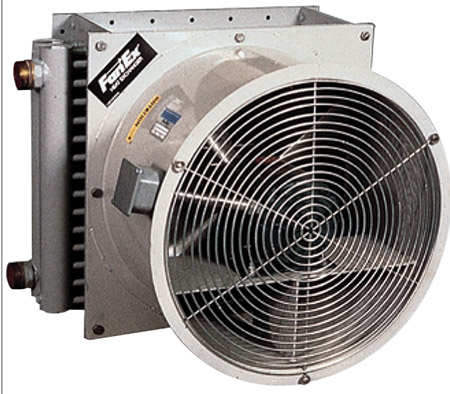
FIGURE 3. In tube-and-fin air-cooled exchangers, a motor-and-fan assembly forces ambient air over a series of tubes, to cool or condense the process fluids carried within. Tapered fins are typically added to the tubes to extend the surface area and maximize heat transfer
Air is readily available, but it is a relatively poor heat-transfer medium. Use of air-cooled heat exchangers can greatly help eliminate the use of valuable cooling-water supplies. To increase the heat transfer rates of the system, the tubes in air-cooled exchangers are typically given fins, which extend the surface area and increase heat transfer.
The diameter and materials specified for the tubes and fins depend on system requirements. The fins are commonly made from aluminum or copper but may be fabricated of stainless or carbon steel. Tubes are generally copper, but can be made from almost any material, and they typically range in size from 3/8- to 1-in. outer diameter.
Typical applications include:
- Oil cooling
- Compressed-air cooling
- Water or glycol cooling
- Heating and air conditioning
- Process heating and cooling
- Air-cooled process equipment
- Energy and solvent recovery
- Combustion air preheating
- Fluegas reheating
Aluminum-bar and plate air-cooled exchangers. Similar to the tube and continuous-fin design, this design also utilizes a motor-and-fan assembly, but instead of tubes, corrugated plates and fins are added to a brazed-composite core, to create alternating air and fluid passages (Figure 4). This compact, lightweight design is considered the most cost-effective air-cooled unit available. Turbulence created in the fluid channels boosts efficiency and reduces required size and surface area. Typical applications include:
- Cooling lubrication oil for power equipment
- Cooling fluids for hydraulic equipment
- Cooling gearbox fluids
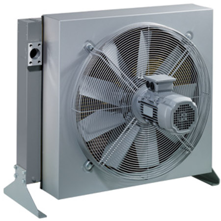
FIGURE 4. This design also utilizes a motorand fan assembly, but instead of tubes, corrugated plates and fins are added to a brazed-composite core, to create alternating air and fluid passages
Concluding remarks
Clearly, for most applications and heat exchanger types, there are a multitude of choices and options available. These guidelines should provide a basis for comparison. No matter what configuration is ultimately implemented, the emphasis on clean, efficient heat recovery ensures that the heat exchanger will remain one of the most critical components in the manufacturing process.
Authors
 John Boyer is the Heat Transfer Commercial Team manager at Xylem Inc. (1 International Drive, Rye Brook, N.Y. 10573; Phone: 716-303-6179; Email: john.boyer@xylem.com). He has additionally held roles in application engineering, product/market management, engineering and general management. Boyer holds a B.S.Ch.E. from the State University of New York at Buffalo and Six Sigma Green Belt Certification, Lean, from the University of Michigan College of Engineering.
 Jim Klimek is the Heat Transfer Global Product manager at Xylem Inc. (Same address as above; Phone: 716-862-4118; Email: jim.klimek@xylem.com). He has additionally held roles in application engineering and product and application-engineering management. He holds a B.S.Ch.E. from the State University of New York at Buffalo.