Presented here are some practical points to help in the selection of a shell-and-tube heat-exchanger design for various applications
Heat exchangers are widely used in various sectors of the chemical process industries (CPI), including: chemical; oil and gas; power generation; food and beverages; heating, ventilation and air conditioning (HVAC) and refrigeration; pulp and paper to name a few. Their use is expecting strong growth over the coming years, driven, in part, by a rising focus on environmental impact and improving efficiency standards.
Although used for varied applications, a heat exchanger’s primary role is to transfer heat from one fluid or gas to another in order to control the temperature of a system and manage waste heat. Growing environmental concerns and regulations are motivating energy-intensive industries to look at ways to improve heat exchanger performance and maximize energy efficiency use.
Choosing the right heat exchanger to fit the needs of specific applications and systems is critical in achieving optimal efficiency.
Operating conditions, ease of access for inspection and maintenance, and compatibility with process fluids are just some of the variables to be considered when assessing heat exchanger options. Other factors include the following:
- Maximum design pressure and temperature
- Heating or cooling applications
- Maintenance requirements
- Material compatibility with process fluids
- Gasket compatibility with process fluids
- Cleanliness of the streams
- Temperature approach
A properly selected, installed and maintained heat exchanger can help enhance the reliability and efficiency of a fluid system by optimizing energy consumption and reducing associated operating costs.
In this article, we look at the specification tips to maximize heat transfer in shell-and-tube (S&T)heat exchangers in order to boost heat exchanger performance and increase efficiency.
S&T exchangers
The shell-and-tube heat exchanger’s flexible design, high pressure and temperature capabilities, and its ability to handle high levels of particulate material make it the most common heat exchanger type used. Mechanically simple in design and a proven technology, the shell-and-tube design offers a low-cost method of heat exchange for many process operations. The following is a brief description of each of the most common shell-and-tube configurations:
Straight-tube, fixed-tubesheet exchangers. The fixed-tubesheet exchanger is the most common, and typically has the lowest capital cost per square foot of heat-transfer surface area. Fixed tubesheet exchangers consist of a series of straight tubes sealed between flat, perforated metal tubesheets (Figure 1).
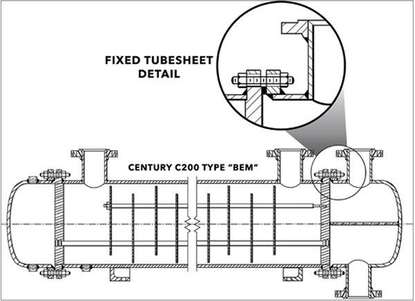
FIGURE 1. In a fixed tubesheet exchanger, straight runs of tubing are attached to two perforated tubesheets. The design has no shell-side gasket or packed joints. This minimizes the potential for leakage, and makes this exchanger ideal for high-pressure operations, or those handling potentially lethal fluids
Because there are no packed or gasketed joints on the shell side, potential leak points are eliminated, making the design suitable for higher pressure or potentially lethal service. However, because the tube bundle cannot be removed, the shell side of the exchanger (outside the tubes) can only be cleaned by chemical means. The inside surfaces of the individual tubes can be cleaned mechanically, after the channel covers have been removed. The fixed tubesheet exchanger is limited to applications where the shellside fluid is non-fouling; fouling fluids must be routed through the tubes.
In line with the Tubular Exchanger Manufacturers Association (TEMA) heat exchanger standards and nomenclature, shell-and-tube heat-exchanger types have a three-letter designation which refers to the specific type of stationary head at the front end, the shell type, and the rear-end head type, respectively.
Common TEMA designations for the straight-tube, fixed-tubesheet exchangers are BEM, AEM, NEN. Common applications include the following:
- Vapor condensers
- Liquid-liquid exchangers
- Reboilers
- Gas coolers
Removable-bundle, externally sealed, floating-head exchangers. Floating-head heat exchangers are so named because they have one tubesheet that is fixed relative to the shell, and another that is attached to the tubes, but not to the shell, so it is allowed to “float” within the shell. Unlike fixed tubesheet designs, whose dimensions are fixed at a given dimension relative to the shell wall, floating-head exchangers are able to compensate for differential expansion and contraction between the shell and the tubes.
Since the entire tube bundle can be removed, maintenance is easy and inexpensive. The shell-side surface can be cleaned by either steam or by mechanical means. In addition to accommodating differential expansion between the shell and tubes, the floating tubesheet keeps shell-side and tube-side process fluids from intermixing.
Although the externally sealed, floating-head design is less costly than the full, internal floating-head exchanger, it has some design limitations due to it being a serviceable joint exposed to the atmosphere: both shell-side and tube-side fluids must be non-volatile or non-toxic, and the tube-side arrangements are limited to one or two passes. In addition, the packing used in this exchanger limits design pressure and temperature to 300 psig and 300°F.
Common TEMA designations are AEW and BEW. Applications include exchangers handling the following:
- Inter- and after-coolers
- Oil coolers
- Jacket water coolers
Removable-bundle, outside-packed, floating-head exchangers. This design is especially suited for applications where corrosive liquids, gases or vapors are circulated through the tubes, and for air, gases or vapors in the shell. Its design also allows for easy inspection, cleaning and tube replacement, and provides large bundle entrance areas without the need for domes or vapor belts (Figure 2).
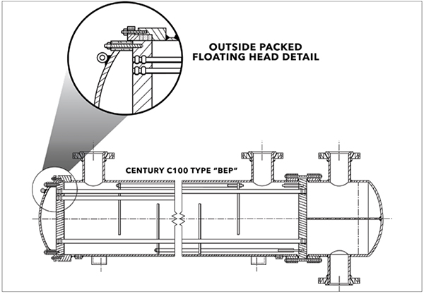
FIGURE 2. In a removable bundle, outside packed floating head exchanger, straight runs of pipe are attached to one fixed (or stationary) head, and one floating head, which allows the entire assembly to be removed for cleaning and repair. Also, the floating head accommodates differential thermal expansion during operation
Unlike the previous design, only shell-side fluids are exposed to packing, allowing high-pressure, volatile or toxic fluids to be used inside the tubes. The packing in the head does, however, limit design pressure and temperatures.
Common TEMA designations are BEP and AEP. Typical applications include the following:
- Oxygen coolers
- Volatile or toxic fluids
- Gas processing
Removable-bundle, internal clamp ring, floating-head exchangers. This design is useful for applications where high-fouling fluids require frequent inspection and cleaning. And, because the exchanger allows for differential thermal expansion between the shell and tubes, it readily accommodates large temperature differentials between the shell-side and the tube-side fluids.
This design has added versatility since multi-pass arrangements are possible. However, since the shell cover, clamp ring and floating-head cover must be removed before the tube bundle can be removed, service and maintenance costs are higher than in “pull through” designs (discussed next).
Common TEMA designations are AES and BES. Typical applications include the following:
- Process plant condensers
- Inter- and after-cooler designs
- Gas coolers and heaters
- General purpose industrial heat exchangers
Removable-bundle, pull-through, floating-head exchangers. In the pull-through, floating-head design, the floating-head cover is bolted directly to the floating tubesheet. This allows the bundle to be removed from the shell without removing the shell or floating-head covers, which eases inspection and maintenance.
This is ideal for applications that require frequent cleaning. However, it is among the most expensive designs. And, the pull-through design accommodates a smaller number of tubes in a given shell diameter, so it offers less surface area than other removable bundle exchangers.
Common TEMA designations are AET and BET, and typical applications include the following:
- Exchangers handling chemical fluids
- Hydrocarbon fluid condensers
- Air or gas compressors
- Inter- and after-coolers
Removable-bundle, U-tube exchangers. In the U-tube exchanger, a bundle of nested tubes, each bent in a series of concentrically tighter U-shapes, is attached to a single tubesheet (Figure 3). Each tube is free to move relative to the shell, and relative to one another, so the design is ideal for situations that accommodate large differential temperatures between the shell-side and the tube-side fluids during service. Such flexibility makes the U-tube exchanger ideal for applications that are prone to thermal shock or intermittent service.
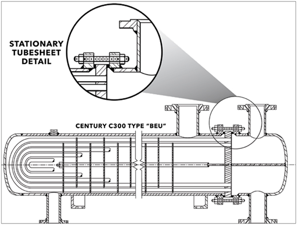
FIGURE 3. Removable bundle U-tube exchangers have only one tubesheet, which allows for maximum differential expansion between the shell and the tubes during operation
As with other removable bundle exchangers, the U-tube bundle can be withdrawn to provide access to the inside of the shell, and to the outside of the tubes. However, unlike the straight-tube exchanger, whose tube internals can be mechanically cleaned, there is no way to physically access the U-bend region inside each tube, so chemical methods are required for tube-side maintenance. As a rule of thumb, non-fouling fluids should be routed through the tubes, while fouling fluids should be reserved for shell-side duty.
This inexpensive exchanger allows for multi-tube pass arrangements. However, because the U-tube cannot be made single pass on the tube side, true countercurrent flow is not possible.
Common TEMA designations are BEU and AEU, and typical applications include the following:
- Oil cooling
- Chemical condensing
- Steam heating
Special designs
For applications with high vapor flow and high-pressure conditions, a specially designed shell-and-tube exchanger is often the only viable solution. Special designs may also be called for when applications have temperature crossing, meaning the outlet temperature of the warmed fluid exceeds that of the cooled fluid. The following are several examples:
- TEMA K-type shells, which allow for proper liquid disengagement for reboilers
- TEMA J-type shells, which accommodate high vapor flows by allowing for divided flow in the shellside
- Two-pass TEMA F-type shells, which can be used for applications when a temperature cross exists
- TEMA D-type front head designs, which are often the answer for high-pressure tubeside applications
While these specially designed heat exchangers may be the solution to a process problem, construction costs tend to be higher than those of “standard” engineered shell-and-tube equipment.
Common TEMA designations include BKU, BJM, BFM and DED. Specially designed exchangers are often called for in the following applications:
- Reboilers
- Steam heaters
- Vapor condensers
- Feedwater heaters
Pre-engineered exchangers
Fixed-tubesheet and U-tube shell-and-tube heat exchangers are the most common types of pre-engineered heat exchangers available today. Such models are often used as components in vapor condensers, liquid-liquid exchangers, reboilers and gas coolers for smaller capacity applications such as pilot plants.
Standard fixed-tubesheet units, the most common pre-engineered shell-and-tube heat exchangers, range in size from 2 to 8 in. in diameter. Materials of construction include brass or copper, carbon steel and stainless steel. Even though this exchanger is one of the least expensive available, it is still generally constructed to standards specified by the manufacturer and not to TEMA specifications. If the user desires, pre-engineered exchangers can be constructed to American Society of Mechanical Engineers (ASME) codes.
U-tube heat exchangers are commonly used in steam-heating applications, or heating and cooling applications that handle chemical fluids as opposed to water. While the U-tube is generally the lowest-priced heat exchanger available, service and maintenance costs tend to be higher than other exchangers, since the nested, U-bend design makes individual tube replacement difficult.
Custom-designed heat exchangers, though more expensive than the pre-engineered counterparts, are generally made to higher design standards than pre-engineered exchangers. Many manufacturers follow the TEMA standards for design, and fabrication following the TEMA industry classifications:
- TEMA B is the most common TEMA designation, and provides design specifications for exchangers used in chemical process service
- TEMA C guidelines provide specifications for units used in commercial and general process applications
- TEMA R guidelines provide specifications for exchangers used in petroleum refining and related process operations
Each of these classes are applicable to shell-and-tube heat exchangers with the following limitations:
- Shell diameter does not exceed 100 in.
- Pressure does not exceed 3,000 psi
- The product of shell diameter (in.) times pressure (psi) does not exceed 100,000
Standards set by the American Petroleum Institute (API) are also generally accepted throughout the heat exchanger industry.
While there are obvious advantages to purchasing a custom-designed exchanger that meets either TEMA or API manufacturing guidelines, these specifications add to the cost of the exchanger and may have a longer manufacturing cycle.
Authors
 John Boyer is the Heat Transfer Commercial Team manager at Xylem Inc (1 International Drive, Rye Brook, N.Y. 10573; Phone: 716-303-6179; Email: [email protected]). He has additionally held roles in application engineering, product/market management, engineering and general management. Boyer holds a B.S.Ch.E. from the State University of New York at Buffalo and Six Sigma Green Belt Certification, Lean, from the University of Michigan College of Engineering.
 Jim Klimek is the Heat Transfer Product & Business Development manager at Xylem Inc. (Same address as above; Phone: 716-862-4118; Email: [email protected]). He has additionally held roles in application engineering and product and application-engineering management. He holds a B.S.Ch.E. from the State University of New York at Buffalo.