These observations and recommendations —reflecting decades of experience — can help operators avoid a lot of headaches and heartache when it comes to handling bulk solids
Successful startup and operation of solids-handling processes depend on myriad small yet fateful decisions that are made during the various phases of the project. Many of these are not quantitative but qualitative in nature, and are largely based on experience and broad-based knowledge of solids handling. It is just as important to know what not to do as it is to know what to do. Since many engineers receive very little formal training on solids handling, their first instinct is to draw an analogy between solids-handling systems and fluids-based systems. This should be avoided. The behavior of solids (powders, pellets and granules) is often counter-intuitive to the behavior of pure fluids.
The guidelines presented here draw upon the collective experience of the authors and highlight key issues that need particular attention. These recommendations are by no means exhaustive, but merely provide a starting point for a thoughtful discussion.
STORAGE
Material Testing and Evaluation
Get a representative and traceable sample. Make sure that the sample is stable over time. If large variability is observed, understand the source (nature and range) of the variability, and collect multiple samples to establish the bounds on physical properties. Proper documentation of sample source and history is helpful in troubleshooting if the hopper does not perform as expected.
Variations in product condition arise for various reasons, most of which fall into the three general classes: uniformity, consistency and stability. Materials that initially have uniform composition may change during handling; for instance, if segregation occurs, the material may demonstrate different bulk properties. Meanwhile, supply inconsistencies may result from seasonal or process variations, or the need to secure materials from alternative sources. The product may also change with time, temperature, attrition, or through natural degradation or other mechanisms. All these changes must be considered in combination, taking into account the complete range of operating and ambient conditions to which the material may be subjected.
Use shear testing for evaluating material flowability and wall friction characteristics. The Jenike flow-factor tester [1] and Schulze Rotational Shear Tester (RST) [2] are typically used for such measurements. Shear testing is the domain of specialists, but experienced personnel can usually make an assessment of the degree to which such testing may be necessary. Critical arching dimensions, stable rathole diameter, hopper angle required for mass flow and feeder load can be calculated using the proven theories of Jenike and other researchers. A very important note: Sometimes the material’s angle of repose is incorrectly used to calculate bin design parameters. The angle of repose should only be used to estimate the volume of material in the bin.
Perform a wall-friction test on a representative wall sample obtained from the equipment fabricator. For example, a mill-finish aluminum sample from one fabricator may differ significantly from an aluminum sample from another vendor. If the material being handled is highly abrasive, consider the effect of wear on wall friction. Some wall materials become more polished (smooth) with wear while others might become rougher. Similarly, the effect of potential corrosion and oxidation must be taken into account.
Be sure to measure the appropriate bulk density. This critical measurement should reflect the circumstances of the application. For instance, a rapidly filled hopper may require the holding capacity to be based on a “loose poured” density, while one filled slowly may be better assessed using a “settled” density value. On the other hand, “aerated” bulk density should be used if aeration devices are used as flow aids. Care should be taken when dealing with a product that exhibits a wide range of density values according to how it is handled.
Selection, Specification and Design
Establish the range of moisture content, additive content and operating temperature. The design basis should reflect the full range of conditions in which a material is going to be handled and not just “typical” operating conditions. For outdoor applications, consider the consequences of temperature cycling and whether there may be condensation in the headspace (silo weeping) or on walls that may be in contact with the material.
Include discharge rate expectations in your design criteria. The discharge rate of a powder can be severely limited by its lower permeability as compared to a granular material.
Test the material for flowability changes resulting from consolidation over time. Try to anticipate problems that may arise from extended periods of storage, such as those occurring during normal operation, and from plant shutdowns, production cycles or weekends.
Choose mass flow mode. A bin is set to operate in mass flow mode when all material in the bin is in motion while the material is being discharged. When this does not occur, the bin is operating in funnel flow mode. In general, a mass flow pattern results in a smaller required outlet size, more reliable flow for cohesive materials and some re-mixing of segregated materials. Typical bin geometries are described in Figure 1, along with selection guidelines.
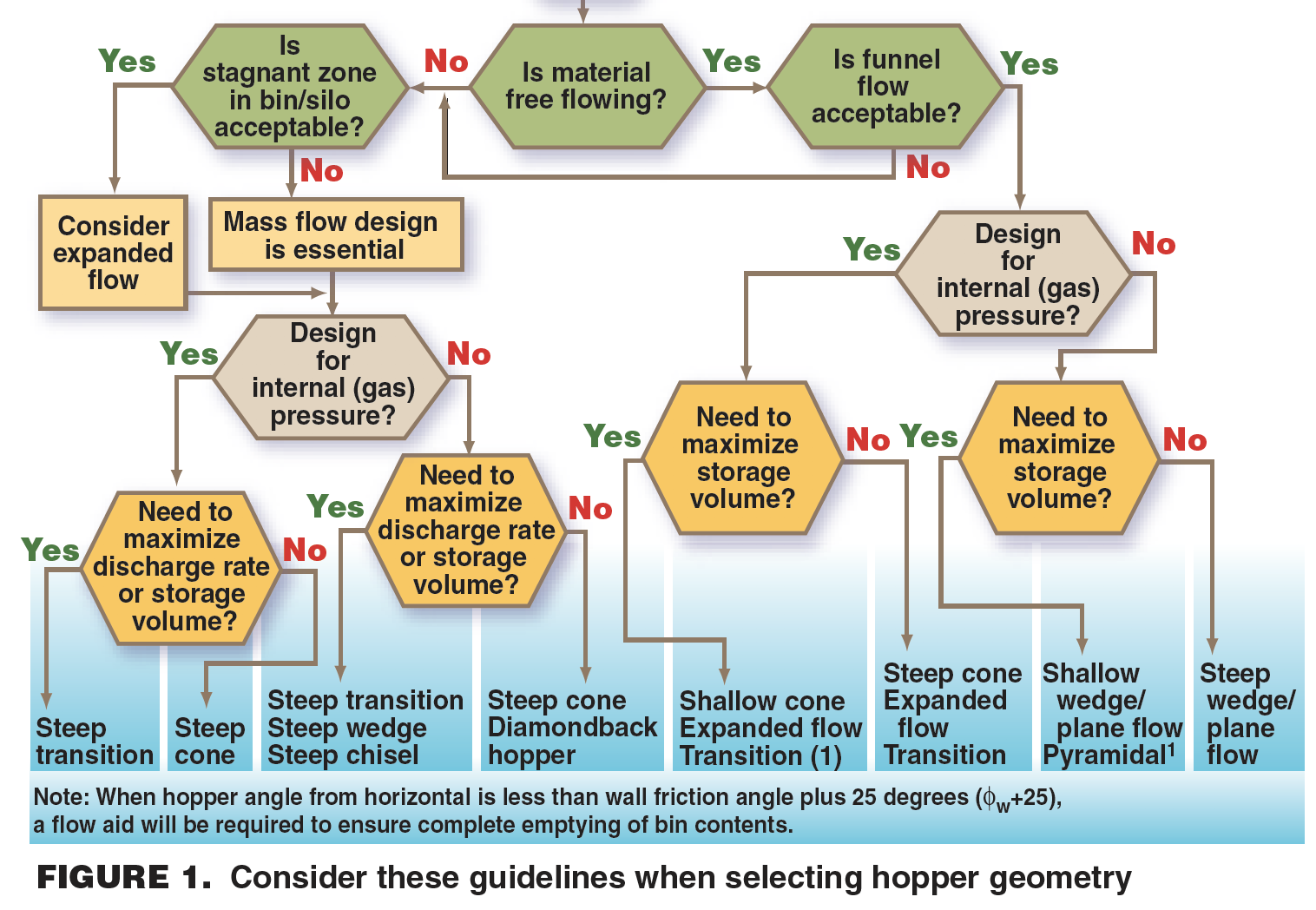
The first-in, first-out nature of mass flow also helps to prevent fluidizable powders from flushing straight through the hopper. It should be noted that the first-in, first-out flow pattern in mass flow can only be achieved if there is at least one diameter head of material in the cylindrical section of the hopper. This is a requirement to get a uniform draw of material during discharge.
Mass flow hoppers are typically taller than funnel flow hoppers (for a given hopper geometry, such as those shown in Figure 2), due to a steeper cone angle. There are applications where a self-cleaning funnel flow design will provide comparable duty at lower cost; therefore, careful evaluation of all factors is essential.

FIGURE 2. Shown here are five of the most commonly used hopper geometries for bulk solids
Be aware that choice of hopper shape is a multi-factor decision (Figure 1). The decision largely hinges on whether the flow benefits of plane flow, which occurs in a V-shaped flow channel, are justified over the poorer flow behavior associated with a conical or pyramid construction.
Flat walls and rectangular cross-sections allow easy construction and maximize holding capacity but generally have the worst flow characteristics and pressure capacity. Cones contain internal pressures well, but require simultaneous flow convergence in two directions at 90 deg to each other.
By comparison, plane flow allows the use of less-steep walls and permits flow through smaller outlets, but normally requires the use of a well-designed feeder to extract product from an extended slot. Such a feeder must extract product from the total cross-sectional area of the outlet for mass flow applications. The critical arching dimension in a plane-flow channel is half that of the diameter of a circular outlet, provided the slot length is greater than three times its width. For example, a 12-in.-wide slot that is 3 ft long is equivalent in flow terms to a 24-in.-dia. outlet and the walls can be less steep (about 10 deg shallower). Remember, flow aids can also be used to encourage flow for hard-to-handle materials [3, 4], but getting the wall slope wrong is far more difficult to correct.
In retrofit situations, have structural considerations re-evaluated by a trained solids-handling expert. For example, when a funnel flow bin or silo design is converted to operate in the mass flow pattern, the cylinder-cone transition may have to be reinforced to withstand highly localized peak stresses. On the other hand, if a silo that was designed for mass flow is operated with a more cohesive material that forms large voids and ratholes, the additional dynamic loads, due to erratic flow, must be taken into account.
Don’t overlook the value of close cooperation and collaboration with the supplier or vendor. To ensure success, it is important to have agreement on the following issues upfront:
• Definition of operating window, along with extreme bounds of operating conditions and material properties
• Sampling techniques and definition of representative sample (including handling instructions)
• Test methods to be used for product evaluation and eventual performance evaluation
• Expectations on performance validation and financial terms associated with it
• Degree of freedom available to the vendor to optimize total cost of the project and share the reduction in cost with the purchaser
Installation, Operation and Performance
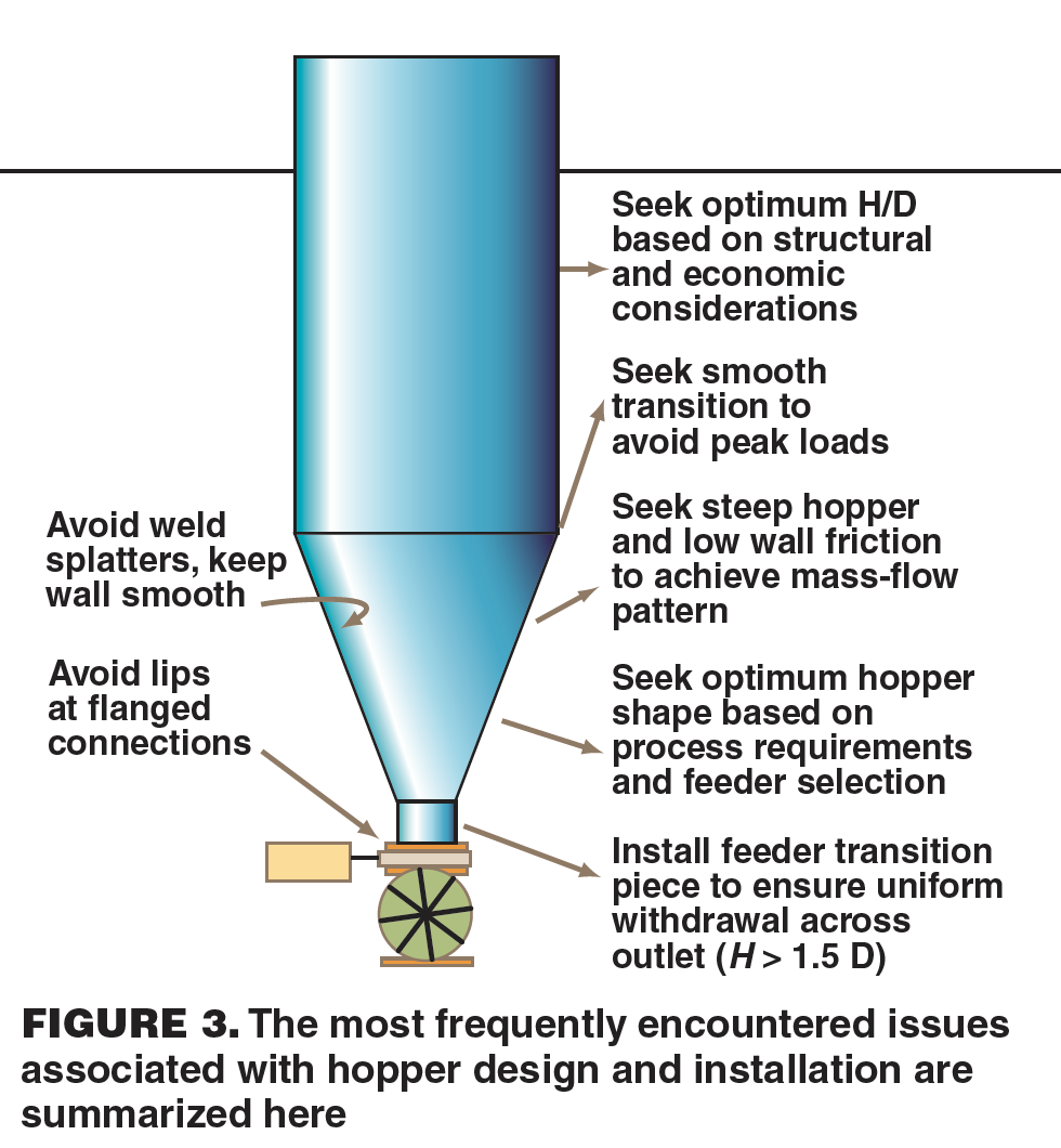
Keep the wall surface smooth. Surface impediments on the hopper wall such as weld splatters, offset flanges protruding gaskets, poke holes and badly installed liners prevent the material from sliding along the wall. Remember the humorous adage: “Protruding lips sink powder ships”
Avoid using a slide gate to throttle the flow because this will result in preferential flow at the outlet. This preferential flow problem can be alleviated by using a vertical transition piece (H > 1.5 D) at the outlet. Slide gates should only be used in the open or closed position. The inner diameter of the bottom flange can be slightly oversized to avoid any lips or protrusions in the flow path.
Avoid asymmetric stresses. Do not cut into the walls of a hopper to create additional discharge outlets. In most cases, they will disrupt the mass flow pattern and create high wall stresses.
Protect the wall finish and liners of the cone from the weather to prevent oxidation (rust) and corrosion. The internal surface of the hopper must be protected from fabrication until the time it is installed in the process. Make sure that all the protective liners are removed before commissioning the hopper. Avoid welding on cones with liners and wall coatings since the heat can cause delamination.
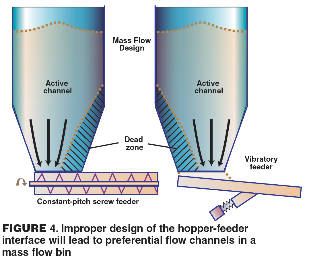
Avoid improper selection and installation of a feeder, which can destroy the flow pattern in a well-designed mass-flow hopper. Reliable flow out of a mass-flow hopper requires the material to be discharged across the whole cross-section of the outlet. For example, a screw feeder with progressively increasing pitch offers a proven option for drawing material across the entire outlet.
Some common installation issues discussed in this section are summarized in Figure 3.
FEEDERS (PROCESS AND ADDITIVE)
Material Testing and Evaluation
Conduct trials under realistic conditions. Materials that are sensitive to heat and moisture may appear to be well-behaved in air-conditioned labs. This can produce false confidence based on test results.
Establish feeding accuracy requirements. It is important to know whether feed rate control or totalized weight is required by the process. The time basis for calculation of feed rate accuracy must be established. Make sure that acceptable accuracy is achieved at the lowest feed rate.
Run extended trials (1–7 days) on new materials or critical applications. Many problems do not appear in short-duration (< 1 day) tests. Consider renting a unit for longer-term pilot-scale testing.
Be sure to test representative materials. Often times, offline tests are done on materials that do not reflect flow properties of actual material in process. Such tests may be misleading.
Selection, Specification and Design
Define operational requirements. Does the process require the material to be fed at a target rate (e.g., in a continuous blending operation), or to deliver a target totalized weight in a batch operation (e.g., in a packaging operation)?
Choose between gravimetric and volumetric feeders. Gravimetric feeders are recommended when feed rate uniformity of better than ±2% is required, especially for sample collection times less than 30 seconds. These feeders are also required for feeding fine cohesive powders with erratic flow, or powders with unpredictable bulk density that are prone to aeration.
Be sure to design the feeder and hopper as an integral unit. The feeder is not merely a “discharger;” therefore, reliable flow out of the hopper is essential for proper feeder operation. A feeder is designed to modulate the flowrate of the material that is reliably fed into it. Material discharge must take place over the entire outlet for a mass flow hopper to work (Figure 4). For some hard-to-handle products (such as those that are cohesive, caking, fibrous, stringy, time consolidation sensitive or hygroscopic), a discharger may have to be installed upstream of the feeder to ensure reliable flow [3, 4].
Plan for sufficient flight tip clearances. Make sure that flight tip clearances for screw feeders are large enough to avoid particle trapping or wedging, which can result in material degradation. On the other hand, rotary feeders require the clearances to be less than the particle size to avoid smearing inside the housing.
Determine whether the feeder is required to provide positive protection against uncontrolled flow that might result from flooding or flushing of fine powders. For example, a screw feeder will not restrain a fluidized powder from flushing out of a hopper. If the product is prone to flushing, install a valve on the discharge port. The valve should be interlocked to be open only when the screw is running, and should have an emergency override switch to close it.
Consider system-integration issues that may arise when feeder electronics are integrated with plant network and process computers. The ability to seamlessly integrate a feeder control package with the plant network and share data and diagnostic information will result in smooth operation.
Be aware that rotary and screw feeders are prone to pulsations in feed rate. Pulsations can be minimized in a number of ways:
Rotary feeders:
•Use a reduced-capacity rotor and ncrease the number of vanes
Screw feeders
• Install wire mesh at the nozzle outlet
• Provide a slot (1.5 times the pitch) on the side of the nozzle
• Install a wedge at the outlet over which the material must flow
• Reduce the pitch near the outlet
• Use a twin-screw configuration
Feeder selection considerations
The following issues must be considered during feeder selection:
1. Material properties
a. Particle size distribution and maximum lump size
b. Flowability and cohesion
c. Air-retention characteristics and their effect on bulk density
d. Flooding or flushing characteristics
e. Abrasiveness
f. Friability
g. Sensitivity to temperature
2. Operational requirements
a. Process temperature and humidity conditions
b. Feed rate (typical, maximum, turndown ratio requirements)
c. Feed rate uniformity versus accuracy and sampling requirements
d. Volumetric versus gravimetric feeding
e. Need for dust control and containment
f. Sealing requirements against pressure
g. Ease of cleaning (frequency of cleaning and acceptable effort necessary)
h. Sanitary requirements (for instance, in food and pharmaceutical applications)
i. Ability to handle unexpected materials (such as tramp metal or nuts and bolts)
j. Headroom constraints
k. Vibrations in the process area and isolation techniques required
l. Controller interface protocol and control system integration with existing plant network and process computer
m. Data and parameters that need to be exchanged, namely, instantaneous flowrate, setpoint, totalized weight, bulk density, alarms, system reset and PID control parameters
n. The location of the controller box vis-à-vis the feeder
A concise comparison of various feeders, shown in Table 1, provides a good starting point. An in-depth review of various feeders can be found in Carson et al. [5] and Thomson [6].
Installation, Operation and Performance
Always confirm that the outlet will not be blocked or obstructed or admit a reverse gas flow. Unvented rotary valves often pass back air by leakage, and via returning vane pockets. With no means of escape, this air can inhibit flow from the hopper. Allow a gas-bypass route to ensure that the material will flow freely into the feeder. Fit a torque limiter or a level detector to isolate the drive if there is any prospect of backup from downstream equipment.
Verify and minimize the starting load on the feeder. It is not uncommon for the starting load to be five times the operating load. During initial filling conditions, a peak stress field is generated in the bin where large loads are transmitted to the feeder. With flow initiation, an arched stress field is developed in the hopper where most of the load is supported by the hopper walls (further discussion on arched stress fields can be found in Jenike, [1]). The arched stress field is retained even if the flow is temporarily stopped. Feeder loads during startup can be significantly reduced by creating an arched stress field; for example, by withdrawing small amount of material during filling. Leaving the hopper partially full before refilling will also achieve the same result.
Provide a slide gate (or some other type of shutoff valve) above a feeder. This is especially important for situations in which the feeder fails and must be removed for maintenance or repairs when the overlying silo or bin is full of materials.
Make sure that the seals are adequately purged to prevent fine powder from entering and destroying the seal. Seal and bearings must be inspected and maintained on periodic basis to avoid premature failure.
Feeders for Pneumatic Conveying Systems
Material Testing and Evaluation
Feeders for pneumatic conveying systems are rarely tested on a standalone basis. Rather, their effectiveness is typically tested while conducting conveying trials. The following issues must be looked into during testing:
1. The effect of gas leakage or aeration on the bulk density of product. Reduced bulk density can result in lower feeder capacity.
2. The abrasiveness of material and its impact on feeder performance
3. Stickiness of material and any resulting reduction in feeder capacity
4. Ease of cleaning and unplugging
Selection, Specification and Design
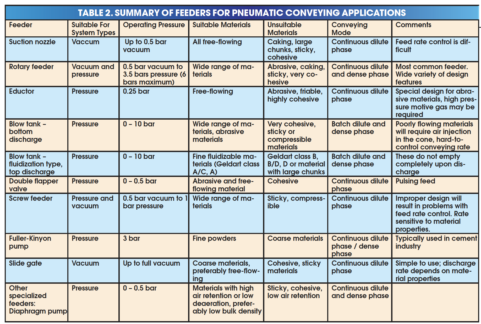
Give careful consideration during the feeder selection process. Feeder selection depends on the mode of operation (pressure versus vacuum), operating pressure, mode of conveying (batch versus continuous), space availability and material properties (such as abrasiveness and cohesion). See Table 2 for more details.
Match feeders with the characteristics of air movers. For instance, feeders that create large pulsations in the feed rate should not be used in systems that use fans as air movers. The interaction between pressure variations resulting from feed rate fluctuations and fan characteristics can result in an unstable system.
Installation, Operation and Performance
Design a proper venting system for rotary airlock feeders in positive-pressure applications. The upward leakage of air through clearances and returning pockets can impede material flow and may reduce bulk density, which can result in capacity limitations. The vent always contains entrained solids and therefore must be designed as a pneumatic conveying system.
Consider the effect of pipe and bolting stresses. Feeders connected to piping system (chutes) that are exposed to large variations in temperatures either due to process conditions or diurnal variations may experience high stresses. This can affect the operational clearances and cause jamming or excessive leakage to occur.
Consider relative expansion that may result from hot product and cold ambient conditions. Relative expansion of feeder internals due to a hot product can cause interference fit and result in a feeder jam. The problem can be alleviated by heat tracing the feeder.
Make sure that the feeder is appropriately designed for quick clean out for sanitary applications. Provide the necessary working space in the process area.
Proper interfacing of feeders with the conveying line is essential. The feeders are attached to the conveying line with a feed shoe or a feed box. A good feed shoe design provides for rapid removal of material from the bottom of the feeder, minimal reduction in local gas velocity at the feed point, and minimal recirculation patterns.
PNEUMATIC CONVEYING – DILUTE PHASE
Material Testing and Evaluation
For materials for which there is no prior pneumatic conveying experience, and for which no related data are available, pilot or full scale testing is recommended. Take the following issues into consideration:
• Conduct tests at material temperatures and moisture levels that are comparable to the process conditions
• Conduct tests on off-grade materials (not just the prime product) to ensure process reliability across a range of material properties
• Consider the effect of attrition on conveying characteristics if the material is being recirculated during the test
• If the conveying line is getting coated (by materials buildup) during the test, the data will exhibit scatter and may not be reliable
Selection, Specification and Design
In the project scope, clearly define current conveying-rate requirements and plant layout, along with plans for future expansions or potential rate enhancements due to improvements in process technology. This should include potential changes in the product slate due to improvements in process technology. Developing the project scope should be a collaborative effort between research, manufacturing and engineering personnel and the outside vendor.
Allow a ‘reasonable’ horizontal conveying length (15 to 20 pipe diameters), before the first bend to allow the bulk material to accelerate. Use of flexible hose at the pickup should be kept to minimum. Excessive length of flexible hose, often in the form of a coil, is the worst pickup pipe configuration. Inability to provide proper configuration at the pickup will result in plugging condition at gas velocities higher than saltation velocity
Consider stepping conveying lines (increasing the pipe diameter) to prevent excessive velocity at the end of the line. Be sure to maintain the minimum required Froude number at the step location, otherwise the material will settle out of the suspension (saltation). Properly stepped systems result in more efficient systems with lower degradation and wear. Using ISO pipes or tubes allows for more choices in diameters.
Be aware that proper venting of the rotary airlock and feeder in a positive-pressure system is critical for reliable operation. Upward leakage of air into the feed hopper can result in reduced discharge rates or an unsteady feed rate. This issue can be addressed by using proper design of a vent system, either using a body vent or a disengagement hopper. The vent system should be designed much akin to a conveying system with sufficient gas flow and minimal bends.
Be aware that product damage and wear at piping bends is very material-dependent. A blind tee piping configuration often has a lot of merit, but may also cause greater pressure drop compared to long-radius bends. Mitered elbows may offer a good compromise in some cases.
Remember that minimum conveying velocity is a function of conveying rate. Make sure that the gas velocity at the pickup is greater than the saltation velocity at the highest solids flowrate. Safety margin must be allowed for non-optimal line configuration at the pickup (such as insufficient acceleration lengths, back-to-back bends, and so on).
Installation, Operation and Performance
Avoid conveying line layout with bends or elbows placed back to back. This will inevitably cause excessive pressure drop and premature line plugging.
Be aware that conveying lines should not be routed like utility lines (i.e., those carrying compressed gas or steam), which follow the contours of a building. When designing solids-handling systems, minimizing the number of bends or directional changes will result in higher capacity, lower degradation, less erosive wear and more reliable flow.
Consider electrostatic effects. Electrostatic effects in pneumatic conveying systems can be minimized by increasing the relative humidity of the conveying air to more than 70%.
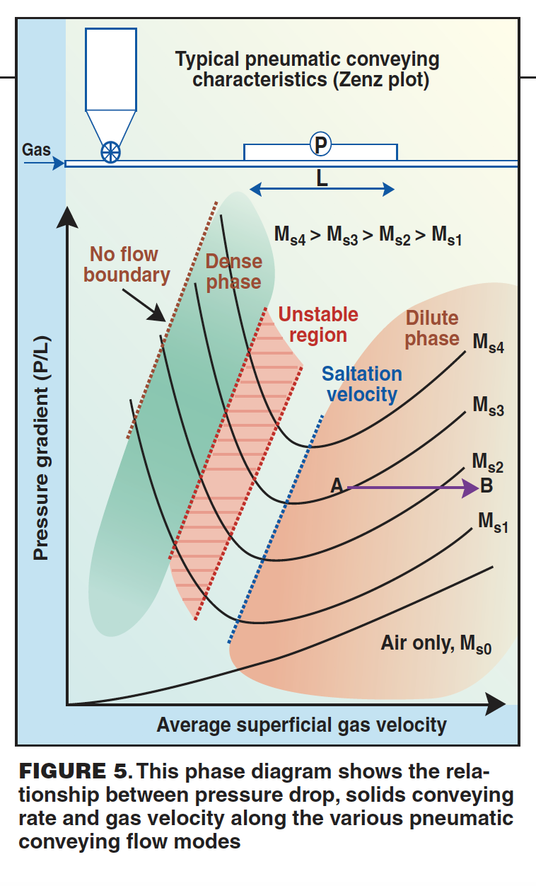
Remember that ‘more air’ can mean ‘less transfer capacity’ in dilute-phase systems. At constant conveying pressure, increasing gas velocity results in reduced conveying capacity (This is shown in Figure 5, at the line labeled A→ B). Operating limits can be best understood using the concept of operating windows (see Agarwal and Dhodapkar [7])
Install sufficient ports or couplings in the systems for pressure measurement during troubleshooting. Pressure measurement is a convenient way to measure the pulse of a conveying system. Take time to generate baseline data for an existing conveying system. It will come in handy for future troubleshooting.
Always verify installation in the field. The technical guidelines of system designers and engineers, even if well-documented, can be undone by contractors installing a system. Common mistakes, such as those listed here, can cause significant delay in successful startup:
• Incorrect rotational direction of rotary airlock/feeder or air movers
• Conveying lines with directional internal treatment (e.g., shot-peening) that are installed backwards
• Poor alignment of flanges or improper seating of gaskets (which can result in air leakage or material degradation)
• Specialized bends or elbows (such as blind tee configurations) that are installed backwards
• No allowance for pipe flexing (which can result in high bolting stresses on the components)
Always verify the control logic and the sequence of valve operation in the field. Follow these recommendations to avoid problems:
• For complex systems, run simulations before startup to understand unintended consequences. A software code is easier to mend than broken hardware during a startup
• Failure to include sufficient time delay between various steps may cause problems. For example, a large slide valve may take as much as 30 seconds to close fully.
• If control loops are being used for feed rate control, tune the parameters and provide upper limits to prevent overshooting. This might result in overfeeding solids into a conveying line resulting in plugged condition.
During startup, verify process instrumentation with field measurements. Make sure that calibration parameters, conversion factors and units are correctly entered, calculated and communicated to the process computers. If possible, use local gages for verification.
More guidelines on troubleshooting pneumatic conveying system can be found in Mills [8], and Dhodapkar and Jacob [9].
PNEUMATIC CONVEYING – DENSE PHASE
Material Testing and Evaluation
Conduct pilot-scale or full-scale testing on representative materials, especially for new or different products where no prior experience or data are available. Benchtop characterization tests (to determine such characteristics as wall friction, permeability and deaeration tendencies) are helpful for preliminary screening of a material’s suitability for dense-phase conveying. Dense-phase conveying performance can be sensitive to variations in material properties (such as particle size, size distribution, shape, density, moisture and cohesion).
Selection, Specification and Design
Ensure that the choice of a flow mode (and system) is based on the product properties (rather than on some imprecise definition or misleading solids-loading assumptions), and that the selected or supplied flow mode is confirmed during commissioning. The term “dense phase” is often misused in practice. For example, many so-called “dense phase” systems are found to be operating in dilute phase (or suspension flow). And, many researchers and designers define “dense phase” as a flow mode with solids loading (mass of solids/mass of gas) greater than 10 or 15.
Many different types of dense-phase conveyors have been developed over the past few decades to take advantage of certain product properties (such as air retention, deaeration, permeability, cohesion, and particle-size distribution). In most cases, “dense-phase” can simply be considered as some form of non-suspension flow that occurs at some time at any section along the pipeline. Using solids loading as an indicator of flow mode can be misleading (for instance, solids loading is a mass concentration parameter that depends on the mass or density of the particles; some dilute-phase systems are operating at a solid loading rate greater than 40, while some dense-phase systems operate at a solid loading rate less than 10).
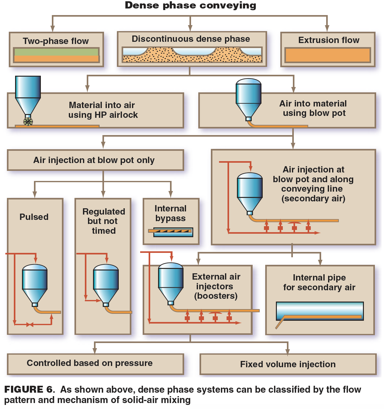
For materials that do not have a natural tendency for conventional dense- phase conveying, consider specialized systems with controlled and regulated gas injection or bypass pipeline technology (Figure 6). Ensure that proper dense-phase flow is actually achieved during commissioning. Using a conventional or “off-the-shelf” pipeline, not all materials can be conveyed reliably in dense phase. Some materials can be conveyed in single- or multi-slug/plug mode, some in fluidized moving-bed type flow, while others can only be conveyed in dilute phase. Not selecting the right flow mode for a particular material, or the right operating condition for a given flow mode, can result in excessive pressure spikes, system shutdown, unstable vibrations and pipeline blockages.
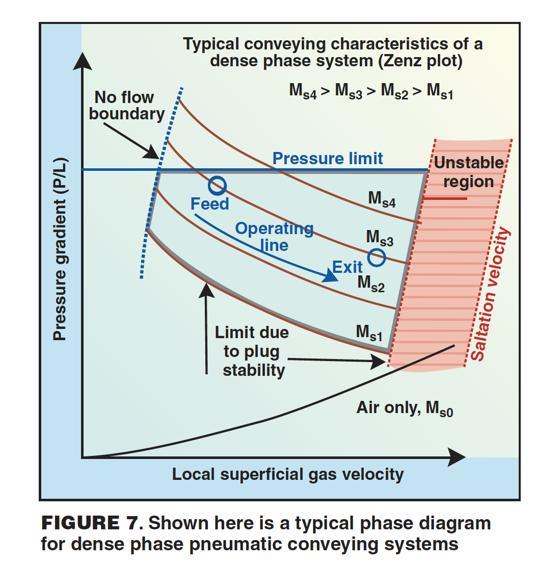
Compared with dilute-phase conveying, the dense phase regime can be more limiting and sensitive to variations in air flow and conveying rate. For some materials, a reduction in solids flowrate can shift the operating point into the unstable zone, thereby causing severe instability (evidenced as line vibrations and pressure spikes).
Ensure proper venting at the feeder to avoid feeding problems that may result from gas blowback. Feeder gas leakage can be a significant fraction (up to 50%) of total gas consumption. The gas leakage at the feeder (especially through rotary valves) must be considered in design calculations and compensated appropriately.
Use a gas-flow control system for multiproduct and multi-destination systems, to ensure that the operating point is maintained within the stable operating zone. Also, ensure that the gas-flow control system provides a constant gas mass flowrate for the full range of operating pressures and pressure fluctuations. Numerous control logic schemes are available from various vendors or can be designed by reputable consultants.
For systems with high pressure drop (7 psi or 50 kPa and higher), consider stepping the line diameter to reduce the velocity and maintain dense-phase conditions. In dense-phase systems, gas expansion can be significant between the feed point and destination. This will result in a corresponding increase in gas velocity, and a possible transition from dense- to dilute-phase flow along the conveying pipeline.
Remember that selection of optimal feeder is critical. Improper feeder selection can result in unreliable operation and high maintenance costs.
Installation, Operation and Performance
Make sure that the operating point (gas flowrate, solids flowrate) falls well within the bounds of plug stability at all locations in the system and for all pipeline configurations (if applicable). Coarse or granular materials that can be conveyed in dense phase (low-velocity slug-flow mode) exhibit an unstable operating zone in between (high-velocity) dilute-phase and (low velocity) dense-phase conveying. The dense-phase regime is bound by a high-velocity (unstable zone) boundary and a low-velocity (blockage) boundary (see Figure 7 for details).
A proper purge-control sequence may need to be designed and tested to avoid unnecessary product degradation or pipeline blockage. To purge a dense-phase line during cleaning, a controlled increase in gas velocity may be required. The dust collector must be designed to handle the peak gas flow rates.
Work closely with an experienced vendor to design and install proper pipeline supports, to prevent excessive deflection and line movement and reduce the prospect of fatigue failure. The motion of slugs and stresses generated within the conveying line during directional changes (such as those that occur at bends or diverter valves) results in significantly higher stresses on pipe supports as compared to dilute-phase systems.
In summary
The guidelines offered here provide a good starting point for designing a reliable bulk solids handling system involving selection, installation and operation of a silo, feeder and conveying system. Each new project offers unique challenges, especially with ongoing innovations in polymer science and fine (even nanoscale) particle production. The secret to success lies in understanding the fundamental concepts of solids handling, using material characteristics (real data) for designing, matching hardware performance specifications with the process requirements and paying attention to details during design and implementation.
Edited by Suzanne Shelley
