Severe service valves (SSVs) differ from general purpose valves in important ways. Presented here is guidance on how to increase service life, reduce costs and improve safety and environmental performance of SSVs
Severe service valves (SSVs) are often identified by applications that challenge the valve’s ability to survive, but the term SSV can mean different things to different people. In the past, defining SSVs had little, if any, global agreement or common recognition. That is about to change as the Manufacturers Standardization Society (MSS; Vienna, Va.; www.msshq.org) has accepted an application to produce a standard practice document to define them.
Within these challenging applications, the conditions that make the service severe are being analyzed, quantified and qualified. From this effort, it is expected that objective and repeatable definitions will arise, along with guidance to improve the performance of SSVs, reduce unnecessary costs, provide longer service life and process runs, improve safety and reduce environmental issues.
This article provides information about the selection of SSVs in all chemical process industries (CPI), but focuses on metallurgical processes and applications, and offers examples to illustrate both the successful and unsuccessful use of this type of valve. The intent of the article is to raise the awareness of SSV considerations for all industry stakeholders, including suppliers and manufacturers, specifiers and users, as well as owners. The article also supplies tools to better understand where and why SSVs shoud be categorized separately from commodity, or general purpose valves (GPVs).
SSVs can be found throughout the CPI. However, certain industry sectors have many more SSV-related challenges than others. For example, municipal water treatment will have fewer SSV opportunities or needs than the mining or chemical industries.
In general, valves have two basic uses; they either control a process variable (like pH), or they isolate the process. No matter what type of valve — ball, butterfly, check or globe — all fit somewhere into the basic role of control or isolation.
Severe service control valves
The dilemma facing all users of SSVs is for the valves to remain in service providing their singular functions while performing at the basic level required by the process. Severe services challenge both performance and life expectancy. SSVs must deliver a minimum performance over a minimum period of time. The valve industry does have a better understanding and agreement of what defines a severe service control valve (SSCV). Table 1 provides some reasonable thresholds that can be applied to any control valve situation and be used to make a reasonable determination that the application is severe and therefore requires a SSV.
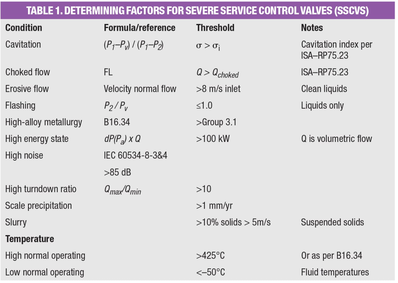
An example of a situation that would require an SSV would be where the fluid will likely be at or near a cavitating state. International Society of Automation (ISA) standard RP 75.23 provides basic formulas that can be used to determine whether or not a fluid will cavitate in service. At a state of cavitation, fluids are accelerated and their vapor pressure is reduced in a proportional relationship. If the pressure drops below the media’s vapor pressure, the fluid will separate into two or more phases — an effect known as flashing. Flashing by itself can and will be erosive to valves and other equipment, but if the downstream pressure recovery is such that the fluid is above its vapor pressure, the resultant collapse of the flashed gas creates the damaging condition of cavitation.
Severe service isolation valves
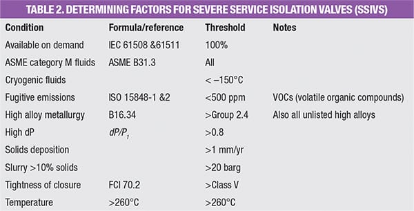
For isolation valves, the valve industry has far less agreement and acceptance on definitions of SSVs. Table 2 provides some reasonable thresholds, although it is admitted, the valve community is still debating and discussing these thresholds, and it appears that a combination of these thresholds may need to be present in order to qualify as severe. For example, if we use the temperature threshold of 260°C — the upper useable limit of fluorocarbons — this eliminates one of the best available options for seat materials, and users would be forced into using metal valve seats, which are far more challenging to use and achieve “tight” shut-off isolation performance. “Tight” itself needs further definition and objective measurements and is in fact also being defined by MSS.
Most isolation-valve datasheets lack a clear expectation of isolation performance. For many in the CPI, the standard FCI 70.2 from the American National Standards Institute (ANSI; Washington, D.C.; www.ansi.org) is used blindly as the performance level. It is common to see Class V or Class VI listed frequently as leakage classifications. These classes offer a measurement for “allowable” leak rate. The anomaly is that the title of the standard is Allowable Leak Rate for Control Valves. Control valves can leak because they should not be used as isolation valves, and SSIVs should not leak.
The valve industry is only now catching up with the demands of the highest performance valves and is providing industry users with better tools than those that have been available in the past. For instance, currently, there is no industry standard for isolation-valve performance that does not allow some passing (seat leakage). One can reference a valve test standard, such as the American Petroleum Institute’s API 598 or ISO 5208 from the International Organization for Standardization, and add a required performance statement, such as “valve seat testing to API 598 resilient seat.” However, doing so eliminates metal-seated valves as options for selection, even though some metal-seated valves are capable of the tightest isolation. For now, the most common isolation valve performance standard in North America is ANSI FCI 70.2, although it has no category for zero seat leakage.
An example of a severe service isolation valve (SSIV) would be a situation where the process requires a degree of isolation tightness after two continuous years of installation that exceeds the tightness allowed in FCI 70.2 Class V. A typical application for this example could be a high-pressure steam boiler drain. This is because a drain valve contains the energy inside the boiler until it is time to empty the valve, and while isolating the steam, any passing (leakage) will lead to loss of efficiency, wasted resources (fuel, demineralized water), and that leakage will lead to increased seat wear and even more leakage.
Valve selection data challenges
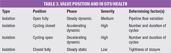
The focus on SSVs has uncovered a lack of data that has been responsible for making the proper selection of SSVs more challenging and therefore more prone to failures. When the datasheet of a control valve is compared to one for an isolation valve, observers will commonly discover that a fundamentally important element is missing from the isolation valve datasheet. The static conditions will be presented in the datasheet, along with maximum design temperature, pressure, pipe size, media, class, material of construction and often flowrates from minimum to maximum. For a control valve, this is all that is really needed because the control valve operates 100% of the time within the dynamic conditions that can be calculated from the data between minimum and maximum flowrates. But for an isolation valve, which is typically static for most of its service life, without knowing the number of cycles and normal operating position (normally either open or closed) engineers cannot properly consider the effects of the dynamic conditions that occur when transitioning between open and closed or vice versa (Tables 3 and 4). It is this transitional state that exposes the valve to very different conditions than those when it is at rest and when it is most vulnerable.
When isolation valves leak, passing energy in the form of differential pressure can produce a velocity increase and the media can become a destructive agent, removing mass from the seating areas. This makes the leak worse, and eventually the isolation valve is incapable of operating in its intended form.
Determining the minimum level of isolation that is required at the end of the service life of an SSIV is critical. That demands understanding what the lifecycle of the valve will be and all of the conditions that will be experienced during the valve’s life. Without this full knowledge, it is extremely difficult to select the valve type, the sealing system, materials of construction and the valve bore, in addition to the operation, whether manual or automated, and special options demanded by the application.
Differentiating SSVs from GPVs
A simple definition of a SSV is a valve that survives in a given application for a defined duration while performing a basic function (isolation or control) up to and until the agreed duration is reached. Those valves that cannot demonstrate this performance level are classified as general purpose valves (GPVs).
As indicated earlier, isolation valves have a more challenging definition than control valves. Severe services are identified by applications. If the process is such that the temperature, pressure, velocity, abrasiveness, corrosiveness or some combination of these parameters challenges the valve’s ability to maintain a basic performance level, then a valve that succeeds in that application is an SSV.
SSVs are important because the consequence of a failure or degradation of performance will have a higher negative impact on the process within which it is operating than GPVs. It may be a surprise to most that not all isolation valves isolate to the same ability or tightness, nor do all types of isolation valves have similar or even close performance abilities. Tightness is relative and often misunderstood. In general, the valve industry has done a poor job of being sufficiently transparent and objective.
It is important to understand that not all isolation valves need to be perfect in the duty; the application will always dictate what is actually required and there will be applications where some through-leakage is unimportant, while for others, it will be critical. This article will shed some light on both ends of the spectrum.
As stated earlier, SSVs can be used in nearly every process and industry, but they are essential in a few. The chemical industry uses a large number of SSVs and some will be examined here. While in a technical sense, all substances are chemicals, for the purpose of this article, the examples discussed involve chemicals that, if their containment is lost, can cause great damage to personal health, property and equipment. A good example of such a chemical is hydrochloric acid (HCl).
HCl is corrosive; it will literally dissolve metals into solution, and if the integrity of the containment of the hydrochloric acid is lost, then the acid may present multiple hazards to unprepared people, equipment and ancillary processes. Corrosion is one of the key elements in the determination of SSVs — an SSV’s resistance to corrosion is often of paramount importance.
Defining SSVs for chemicals
While there are many benign chemicals (water is a chemical), many chemical manufacturing processes and the chemicals that are used and produced are dangerous. They can be toxic, explosive, aggressively reactive or corrosive. These types of chemicals need containment and management so that they are not released in areas where their properties can result in damage or where they can be lost to the downstream process for which they are designated.
For containment of hazardous chemicals, if the purpose of the valve is isolation, then resistance to corrosion from the process fluid needs to be considered carefully. Design codes like the American Society of Mechanical Engineering standard ASME B16.34 provide operating pressure and temperature limits for each pressure class at various operating temperatures for categories of materials. For example, valves of ASME Standard Class 300 for Group 2.2 materials, consisting of several grades of stainless steels including the common forged and wrought 316 and cast CF8M steels, have a working pressure by Class (in psig) at a range of temperatures. A Class 300 valve of this material operating between –29 to 38°C, has a 720-psig pressure limit, the valve’s maximum allowable working pressure (MAWP).
In order to meet that working pressure, the manufacturer will produce a valve body with a minimum body-wall thickness. This wall thickness will be thicker than necessary to provide an additional safety margin. In factory testing, this extra safety is proved by pressurizing the body to 50% beyond the MAWP during its factory hydro-test.
If the corrosion begins to reduce the wall thickness either evenly or in discrete pockets or sections, the valve becomes vulnerable to loss of containment. When referring to the sulfuric acid isocorrosion chart (Figure 1), lines depicting less than or equal to 20 mpy (milli-inches, or mils, per year) corrosion. Note how alloy CF8M is only suitable for very weak or very strong acid at low temperatures and alloy CD4MCu disappears from suitability, while two others that were in the same suitable category remain for a range of higher temperatures.
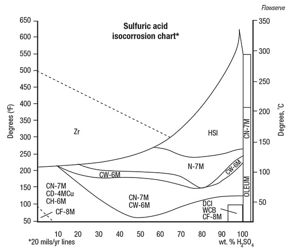
FIGURE 1. This sulfuric acid isocorrosion chart depicts corrosion performance of several materials
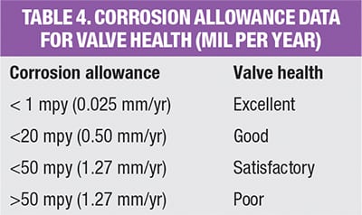
Respecting the overall piping system’s corrosion allowance, often expressed as x mpy, engineers should generally select valves with a trim (the sealing parts) that have a corrosion rating of less than 1 mpy, while the valve body would have a corrosion rating of less than 20 mpy. This practice leads to examining the body-wall thickness during the time the piping is examined. Some applications requiring SSVs would demand a lower corrosion allowance, based on the severity of an upset, the time period between maintenance turnarounds or minimum process runs.
SSVs in pulp and paper
An example application of SSVs is in the pulp-and-paper industry, where chemicals for bleaching the pulp have evolved from chlorine (Cl2) into less dangerous chlorine dioxide (ClO2), sodium hypochlorite (NaOCl) or hydrogen peroxide (H2O2). For the kraft pulp process, cost efficiencies have encouraged the mills to create the necessary chemicals required on-site in a plant within a plant, known as Chem Prep. One process within this sub-plant can produce the bleaching agent — chlorine dioxide.
Chlorine dioxide can be made by reducing sodium chlorate in a strong acid (sulfuric or hydrochloric acid) solution and a reducing agent like methanol, hydrogen peroxide or sulfur dioxide. The basic production route is: chlorate + acid + reducing agent ➞ chlorine dioxide + byproducts. A commercially important production route uses methanol as the reducing agent and sulfuric acid for the acidity. Advantages of not using chloride-based processes are two-fold; the formation of elemental chlorine is eliminated, and sodium sulfate, a valuable chemical for the pulp mill, is a side-product.
Lessons learned
Decades worth of experience working with SSVs in the CPI have allowed the author and other industry experts to glean many important lessons. The following are three that are helpful to consider when selecting your next valve.
Lesson 1: Consider the whole application. The photograph in Figure 2 is a testament to the idiom that “you get what you pay for,” and it shows the importance of considering the application holistically to avoid adverse outcomes. In 1995, a new copper mine was built in Chile. It was designed to use 85 g/L of weak sulfuric acid to irrigate a heap of copper oxide ore. The acid was sprayed over a huge pile of crushed ore, which leached the copper into solution, where it was later electro-won out into pure copper cathodes. This type of mine and process plant is known as a heap leach-SXEW (solvent extraction, electro-winning).
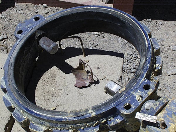
FIGURE 2. The iron disc of this seated butterfly valve was dissolved by sulfuric acid after the PVDF coating was removed by flowing acid
CGIS
 |
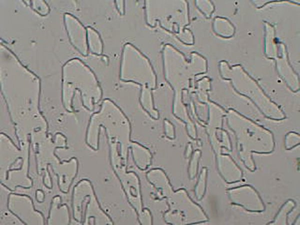 |
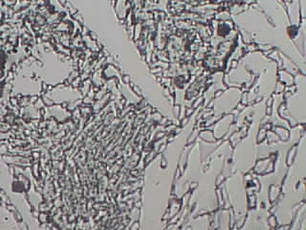
| FIGUREs 3 and 4. Proper heat-treatment of metal valve components can have a crucial effect on valve performance. The micrograph on the left shows a non-heat-treated metal structure at 200-times magification, while the right image shows the metal after heat-treatment (same magnification) | |
The original process designers selected titanium as their corrosion-resistant material of construction for the valves used to direct and isolate the weak acid. These 24-in. valves cost upwards of $60,000 each originally. When a small brownfield project later arose, the local project team balked at the price and decided to investigate alternatives. They checked the corrosion charts and saw that a Buna-N (nitrile rubber) resilient seated ductile iron butterfly valve with a PVDF (polyvinylidene fluoride)-coated ductile iron disc was rated “A” for the temperature and the 85 g/L concentration of sulfuric acid. These valves cost under $6,000 each, far lower and much more attractive for the buyer.
The problem with this type of valve is that they only lasted a few months because they were not used only as full open-or-closed isolation valves. Besides being used to isolate the centrifugal pumps for maintenance, the valves were also used on the discharge of the pumps to assist the pump during startup to develop head pressure. That required them to be placed in the near closed position. Unfortunately, the velocity of the acid that was developed while nearly closed was so high that it physically removed the thin PVDF coating covering and protecting the ductile iron disc. This exposed the iron disc and the acid simply dissolved it. Of note, the originally supplied titanium valves are still in service 22 years later. Sometimes buying cheap costs more in the longterm.
Lesson 2: Use properly processed materials. At a recent valve conference in Düsseldorf, the global audience heard a presentation from the quality assurance (QA) manager of a major global chemical company. The QA manager identified a significant number (more than 35%) of the material test reports (MTRs) for valves and fittings purchased by his company during the year were incorrect, missing, contained obvious errors and, in some cases, were fraudulent. If this is a common occurrence, then the confidence in the valves used in severe service applications is surely mistaken.
The information in the presentation was reminiscent of a situation the author experienced at a plant in Australia in 2006. A distraught client reported a number of valve issues related to the leakage of sulfuric acid in the plant.
An investigation of the situation focused attention on the knife gate valves that had been provided by the author’s company. The manufacturer used castings to make the valve bodies and wrought plate to make the blade. For the casting material, the material selected had been ASTM A890 Gr 5a, a super-duplex stainless steel well suited for the 70–80°F temperatures of the 40 wt.% sulfuric acid in the countercurrent decantation circuit of this hydrometallurgical facility.
For several years, these valves worked flawlessly. The client became very comfortable and decided to try them in an upstream, more challenging process — one in which the temperatures reached 200°F. The higher temperatures resulted in a significant problem. From the isocorrosion chart for sulfuric acid, it can be observed that this acid creates some interesting variations based upon the weight percent and temperature. At the higher temperature, the material had a lower corrosion resistance.
The investigation also exposed the potential for issues using the A890 ASTM method. The non-destructive testing is a little weaker than the more popular ASTM A995 method used today. Metallurgical testing showed that the castings were improperly heat-treated (Figures 3 and 4). While at the lower temperatures, the acid was not as aggressive at exposing the poor manufacturing, but at the higher temperature, the flaws were exposed and the valve failed to contain the acidic solution.
This situation is another case of “you don’t know what you don’t know” and the experience with this issue caused the author’s company to re-evaluate its own QA systems, including purchasing. Key vendors were requested to provide better control of the vendor data to eliminate, or at least greatly reduce, errors that could lead to future valve issues.
Of particular interest, the gate material, which was made from plate (wrought UNS S32750 alloy) was minimally affected by either temperature. This is not to imply that wrought materials are better than cast ones, only that properly processed materials are what is really important.
Lesson 3: Don’t ignore the importance of plastics. Metals are not the only material of construction used to fight against corrosion. Plastics and elastomers are also effective allies in the effort to protect against corrosion from a particular chemical or chemical process. The invention of fluorocarbons like Teflon (polytetrafluoroethylene) and its variants has given the valve industry a wonderful family of extremely corrosion-resistant materials.
Valves for corrosive services are often lined with one of the fluorocarbons, normally Teflon PFA, a perfluoroalkoxy copolymer which can fully isolate the valve body from the process medium. These plastic materials do not corrode like metals, but can and do allow fluids to permeate them. Thus, the quality of their manufacturing to reduce the permeability, the type of liner used, how the plastic components are anchored into the body, as well as the thickness of the lining, are all keys to preventing damage and failure of the less-noble and generally non-corrosion-resistant valve bodies that provide the application’s pressure containment and retention.
Very few solid plastic valves have the strength to withstand the needs of even the lowest ASME B16.34 Class 150 pressure-retaining requirements and are typically rated to a maximum of 225 psig or lower at ambient temperatures. Lined metal-body valves are available fully rated to ASME Class 150 and up to and including Class 300, 720 psig at ambient temperatures. These alternatives to solid metallic valves often offer significantly reduced acquisition costs over high-alloy valves and can provide equivalent long-lasting service lives if selected and operated correctly. Of course, the maxim “the application dictates the valve” applies, and it is incumbent upon the valve selectors to consider all aspects of the valve requirements.
A significant challenge for plastic-lined valves has been that there are no industry standards that provide guidance on what the minimum thickness should be or on any of the other key manufacturing details that make the valve a successful piece of process equipment.
For a Teflon PFA-lined, weir-style diaphragm valve, a typical 3-mm-thick body liner is the norm and is generally sufficient to provide protection for the ductile iron body. This rigid liner is formed over the weir, which serves as the base seat for the moving diaphragm seal (Figure 5). Together, the combination provides the isolation. Due to Teflon’s relatively inflexible and non-resilient properties, the diaphragm consists of a thinner layer cushioned by an elastic resilient material, such as EPDM (ethylene propylene diene monomer) or Viton.
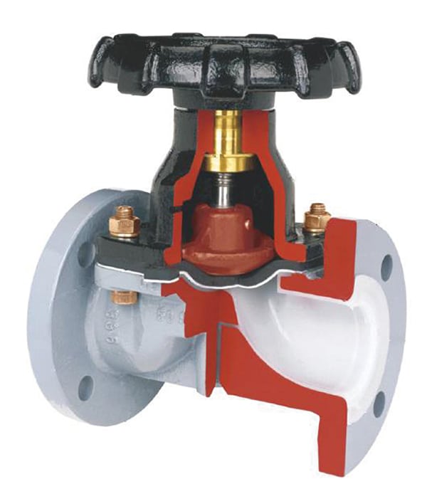
FIGURE 5. Plastic-lined metal diaphragm valves can offer effective solutions in severe-service
applications Gemu
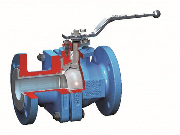
FIGURE 6. This ball valve uses quarter-turn rotary action to open and close, rather than multiturn linear force
Flowserve
This combination diaphragm seal must be able to flex multiple times without distortion or damage. Yet there is a line between how thin the corrosion-resistant liner should be to allow multiple flexing and how immune it is to the stress caused by the closure of the handwheel and that rotary-to-linear torque-to-thrust ratio. Too much torque will cause the PTFE to cold flow and weaken, perhaps to a point where the protective liner is compromised and the liner is torn, exposing the less resistant elastomer cushion to the process media, as well as to an uneven sealing surface that allows leakage even when the valve is fully closed.
When it is impractical or impossible to limit the closing torque’s potential for damage, simply changing valve design can be the obvious solution. One approach is to convert multi-turn linear force into quarter-turn rotary action, as shown in the lined ball valve (Figure 6).
Thankfully, MSS will shortly publish “Plastic-Lined Ferrous Metal Valves” as a Standard Practice. The scope covers plastic-lined ferrous metal valves intended primarily for conveying corrosive fluids. This new tool will recommend minimum liner thicknesses, grades and formulations of plastic liners including PFA, PTFE, PVDF, PP and UHMWPe, liner anchoring, inspection and testing
Summary and future outlook
The valve industry is working to provide better information to ensure the correct selection of SSVs and the proper language to nominate the valve so that it can function in service and meet or exceed expectations. We have discovered the need for more details on the actual process dynamics, including the percentage of time spent during different dynamic conditions, as well as upsets, and to consider what those dynamic situations are doing that could damage the function of the valves, whether immediately or over time as the sum of the damage adds up.
There are many applications requiring SSVs, just as there many for GPVs, and knowing where to draw that line is essential in obtaining the best, safest and lowest-cost valve solutions. In the coming months, the industry will see better tools for identifying SSVs, including new standards for SSV testing, defining SSVs, standard practices for corrosion-resistant-lined valves and deeper knowledge that will assist in providing better valves for the most challenging applications.
Our exposure over the last five decades to a wide range of industrial applications in all of the regions of the world has provided us with an appreciation that communication is a key aspect of success and without it, of failure. Industry’s acceptance of terms like “high-performance” and “tight shut-off” gave false confidence and assurance that valves will work in difficult applications. We have begun to rid ourselves of subjective terminology and have started to bring objective and measureable performance to the task. This greatly enhances everyone’s chances of success.
Edited by Scott Jenkins
Author
 Ross Waters, president of CGIS (558 East Kent Ave. South, Vancouver, B.C., Canada; Phone: 604-263-1671; Email: ross@cgis.ca; website: www.cgis.ca). CGIS parlayed an early focus on chemical processes and exposure to several corrosive chemicals into an eventual specialization in SSVs. The company has expertise in valves using a range of materials, including titanium, Inconels, Hastelloys and fluorocarbons such as PVDF and PTFE. Waters has been involved with industrial valves for over fifty years. Initially working in the bleached kraft pulp-and-paper industry and learning from Canadian chemical-plant-engineering company Chemetics, Waters grew his passion for supplying the highest performance valves into a life-long pursuit. Today, Waters serves on the ASTM Gaseous Oxygen Committee and the Manufacturer’s Standardization Society as a task force member on C-114 Steel Valves and C-409 Knife Gates. He also chairs the task force committed to publishing a new standard on severe service valves.