Operational troubleshooting guidance is provided for several scenarios involving trapped non-condensable gases in distillation towers
Non-condensable gases are often present in distillation towers, either expectedly or unexpectedly. When they do appear, or when the quantity of non-condensable gases varies from the design or expectation, they can adversely affect condensation, cause instability or lead to excessive venting and product loss. Some of the causes of gas trapping issues are well known, while others remain obscure. This article briefly describes the better-known issues, while focusing on those that are more obscure, presenting experiences in which non-condensable gas trapping led to operating problems. Gas trapping issues in distillation towers can be classified into three groups:
- Gas trapping due to tower or auxiliary equipment hardware
- Gas trapping due to liquid head
- Unexpected quantity of gas (high or low) entering the tower
Each of these points are addressed and discussed in this article, with some guidelines for preventing and overcoming gas-trapping issues.
Equipment-related gas trapping
Gas-trapping issues associated with the tower equipment itself, or its auxiliary equipment hardware, are some of the more common and better-known issues, and are therefore only discussed briefly here.
Condensers and reboilers using a condensing heating medium. Gas trapping in condensers and reboilers is well known, and is discussed at length by many references [1– 5]. A famous statement by Smith [3] is that to troubleshoot a condenser, one needs to ask three questions: “Is it clean? Is it vented? Is it drained?” Prof. Bell, the legendary heat-transfer expert, estimated that inadequate venting of non-condensable gases accounts for half of condenser malfunctions [2]. Twenty years later, a malfunction survey [6] reinforced his statement with a slightly smaller fraction of 41%.
Accumulation of even a small fraction of non-condensable gas can impair condensation. The non-condensable gas increases the vapor-phase resistance to heat transfer. In addition, the gas depresses the condensate partial pressure, lowering the condensing temperature and therefore the log mean temperature difference. The diffusional resistance to mass transfer is also important. For film condensation, the heavier components must diffuse to the interface. Heavy components diffuse slowly, and a high concentration of non-condensable gas retards their diffusion. As heavy components condense out, the vapor near the interface becomes leaner in heavy components and richer in non-condensable gas, which further retards diffusion. These mechanisms are responsible for the phenomenon termed “inert blanketing,” which drastically reduces condensation rates in condensers. When the non-condensable gases are acidic or corrosive, like CO2, their accumulation is known to have caused severe corrosion [7, 8, 11].
Several guidelines have been proposed for venting non-condensable gases from condensers and from the condensing side of reboilers [1– 4]:
1. There should be a clear flow path to positively guide non-condensable gases from the exchanger inlet to the vent. If the flow path is governed by baffles, baffle design should ensure adequate sweeping of the gas.
2. The vents should be located at the end of the flow path. Gilmour [9] describes a case history of inert blanketing of the condenser shown in Figure 1 before the vents were added. A similar problem was also reported by others [3].
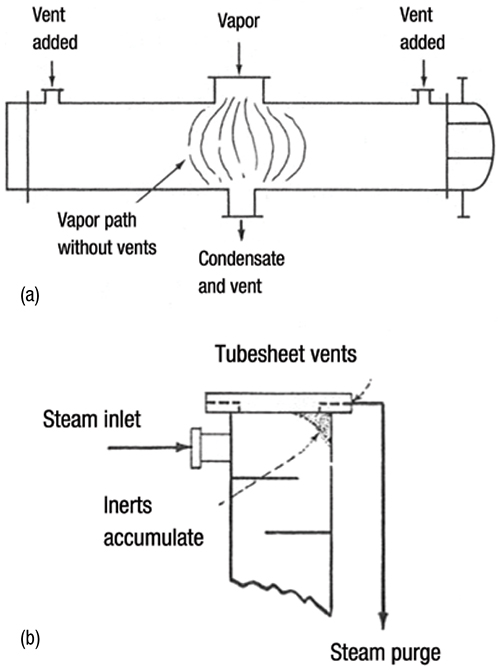
FIGURE 1. Illustrated here are the locations of vents on condensing exchangers to remove non-condensable gas. As shown in 1a, adding properly located vents in a horizontal condenser can eliminate inert blanketing [9]. In 1b, a tubesheet vent is installed in a steam-heated vertical reboiler [8]. (Reprinted courtesy of Chem. Eng.)
3. Figure 2 shows adequate venting of a horizontal thermosiphon reboiler. The balance line goes from below the partition baffle to the top of the condensate pot to minimize condensate backup into the reboiler, as advocated by Risko [5] and Lieberman [7]. Venting is accomplished by cracking valve B open. Opening valve C vents inlet steam, but not the non-condensable gas, so it is useful only for clearing the air out during startup. Similar principles apply to some in-tube condensers, but there the vent valve B is usually mounted on the reflux drum.
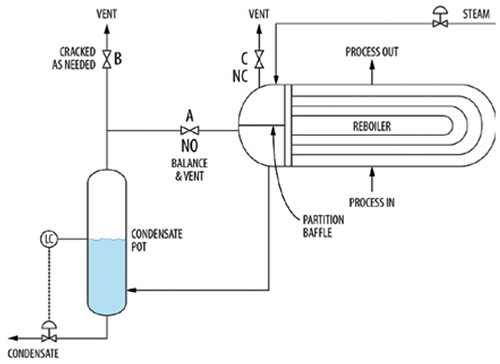
FIGURE 2. This configuration shows adequate venting in a horizontal thermosiphon reboiler. The balance line and vent are drawn from below the partition baffle
4. The flow path should preferably be tapered to maintain high velocities and to avoid gas collection in dead pockets.
5. The effect of different cooling conditions on the regions where non-condensable gases are trapped should be considered.
6. All vapors to be condensed should be considered to contain non-condensable gases. Note that 100 parts per million (ppm) of non-condensable gas in a vapor can fill a reboiler up with non-condensable gas in less than 10 h [2].
7. In vertical reboilers, it is a good practice to provide tubesheet vents [1, 8– 10], as shown in Figure 1b, opposite the top vapor-inlet nozzle. This is essential if the non-condensable gas is acidic or corrosive, such as CO2.
8. Carefully review the vent line piping to ensure it is not choked by a liquid head.
9. Carefully review the condenser design for the possibility of Rayleigh condensation. This occurs when liquid condensed close to the condenser entry, rich in heavy components, is removed as soon as it is formed, and is no longer mixed with the remaining condensing mixture. This mode concentrates the non-condensable gas in the condensing mixture, lowering the vapor dewpoint, and preventing its removal by absorption in the condensate. Case 1.13 in Ref. 15, contributed by Hollowell, describes a case where “an entire refinery capacity was sometimes limited by the gas rate, that was calculated to be zero” (because Rayleigh condensation occurred but was not accounted for in the design calculations).
10. Adequate venting is most important during startup, when air or nitrogen is likely to be present.
Trapping of gas in liquid collection sumps. Liquids in towers are collected in bottom sumps, chimney trays, downcomer trapouts, redistributors and collectors. These liquids inherently contain gas or vapor bubbles. As a rule of thumb, a degassing time of 0.5 to 1 min is needed to degas this liquid [1]. In addition, gas or vapor can be entrained into these liquids by frothing (known as “waterfall pool effect”), gas jets directed into the liquid, flashing (especially when hot and cold liquids are mixed) and vortexing. This subject is discussed at length in Ref. 1.
Gas trapping by liquid head
The mechanisms of gas trapping by liquid head are not as well-documented or widely discussed, and therefore are presented in more detail here.
Trapping of gas by liquid level at drum, condenser, or bottom sump baffles. This is the most common mechanism in this class. An excellent example of this issue is described in detail in Case Study 24.3, co-authored by Olsson and the author in Ref. 15. Overheads from a chemical tower (Figure 3) were condensed in a spray condenser by direct contact with cooled circulating reflux. The condenser drained freely to the reflux drum. Non-condensable gases from the reflux drum went to the vacuum system. The tower experienced pressure fluctuations and intermittent flooding near the top.
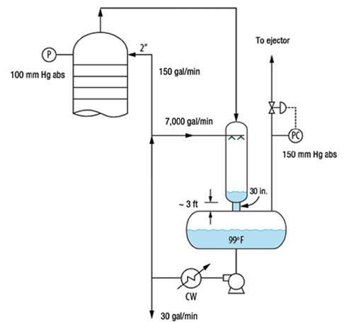
FIGURE 3. This tower experienced pressure fluctuations and intermittent flooding near the top due to gas trapping by the liquid leg in the drain pipe from the direct-contact condenser
A key observation was that the reflux accumulator was at 150 mm Hg, while the tower top was at 100 mm Hg. This can only be explained by a liquid leg in the condenser and in the short pipe between the condenser and reflux drum pulling the other 50 mm Hg of the vacuum in the tower. Operating records confirmed that the 50 mm Hg pressure difference was established as soon as liquid circulation was established, meaning it occurred before vapor was flowing through the tower. This pressure difference was therefore produced by the liquid. The short 30-in. dia. pipe was 3 ft long. At the normal circulation rate, there was an estimated pressure drop of 1 ft of liquid in the pipe (mostly entrance and exit). This leaves 2 ft of net suction, which roughly coincides with the pressure difference (50 mm Hg) between the accumulator and the tower. Calculations using the correlation in Ref. 1 showed that the 30-in. pipe was capable of handling up to 5,400 gal/min of self-venting flow. The actual liquid flowrate leaving the condenser was much higher, at 7,200 gal/min. This means that some liquid backed up in the condenser, and that the 30-in. pipe was running liquid-full.
The liquid leg prevented non-condensable gases from freely leaving the condenser bottom. The gases were trapped in the condenser, raising its pressure. With the pressure in the accumulator fixed by the pressure control, the pressure in the tower and condenser would slowly rise, until there was enough pressure difference to push the liquid leg into the reflux drum and release the gas. Once vented, the tower pressure fell. When more non-condensable gas entered the system, fluctuations intensified.
The fall of the tower top pressure during the cycle could have induced intermittent flooding. Once flooded, hot liquid was entrained by the tower overhead vapor. This heavy-rich liquid absorbed some of the lighter components, dropping pressure in the condenser, and aggravating the flooding.
To solve the problem, the pressure controller was relocated from the top of the reflux drum to the tower overhead upstream of the condenser. This kept a steady pressure in the tower and completely eliminated the pressure fluctuations.
In an analogous case, a boiler feedwater (BFW) deaerator drum (Figure 4) would pressure up. Once it pressured up, air removal from the condensate deteriorated, raising the air concentration in the condensate from 10 to 700 ppm. There was also an instability issue — the deaerator drum would pressure up and then the pressure would suddenly be released.
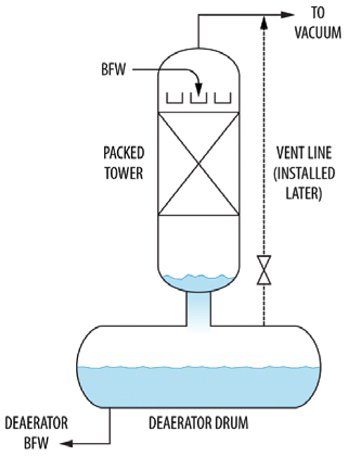
FIGURE 4. This diagram shows a deaerator that was experiencing pressuring up and cycling
The cause was that the drain line from the packed tower above was undersized for self-venting flow. This backed up liquid in the packed tower. Eventually, either a vapor slug broke through or the liquid siphoned out and the process repeated. The problem was eliminated by installing a vent line (shown dashed) from the drum to the packed tower overhead.
Another deaerator (Figure 5) received steam condensate from three sources: 212°F, 240°F and 285°F at variable flowrates, as well as a demineralized water makeup at 90°F. The 12-in. line served both as a vent and a heating line.
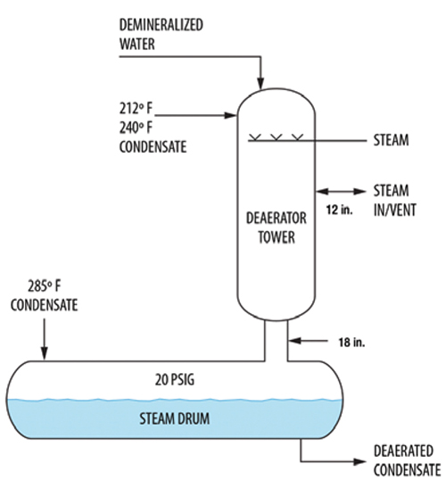
FIGURE 5. This diagram shows an aerator that was experiencing violent shaking
Initially, all three condensate streams entered the top of the tower. Later, the 285°F condensate was routed into the steam drum as shown in Figure 5 to reduce steam venting. Upon restart, at high condensate rates the deaerator shook violently. There was so much flash steam in the drum that the vapor velocity up the 18-in. line was high enough to exceed the system limit [16]. To stop the shaking, the drum pressure was raised from 12 psig to 20 psig, which lowered the vapor velocity below the system limit. The liquid downflow rate of about 300 gal/min was not high for an 18-in. line, so the problem was vapor-driven.
Trapping of gas generated by liquid jets. Liquid feeds often enter the tower as liquid jets. When liquid jets impact on a liquid surface, they entrain vapor into the liquid. When the entrained vapor cannot freely vent out, it may cause liquid backup, as in the situation described below.
A parting box is a rectangular box typically mounted right above packed-tower distributor troughs (Figure 6). A feed sparger pipe elevated just above the box and oriented parallel to it supplies liquid to the box. The pipe may contain holes in its underside or dip tubes that transport the liquid to near the bottom of the box [ 12]. The liquid may be overhead reflux, collected internal liquid mixed with liquid feed, or pumparound return liquid. Holes in the floor of the parting box, located above each of the troughs, meter the liquid to each trough (Figure 6), targeting a uniform liquid head in all the troughs.
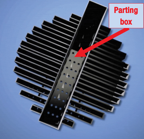
FIGURE 6. A parting box serves to meter liquid to the troughs of a packing distributor. In this distributor, there are holes in the bottom of the troughs, visible in the three troughs in the bottom left of the photograph (Reprinted courtesy of Fractionation Research Inc.)
When feeding the box from a sparger containing holes in the underside (no dip tubes), the liquid jets issuing from the holes impact the liquid surface in the box, generating intense uneven frothing in the box, which in turn leads to maldistribution of liquid to the troughs. A perforated impingement plate (PIP; shown in Figure 7a), stretching wall-to-wall in the box, mounted 2 to 4 in. above the floor, with perforation area typically 10–20% of the box cross-sectional area, is often used to even the froth. The area of the holes of the PIP significantly exceeds the hole area at the bottom of the parting box, so the PIP does not retard the flow. Rather, it breaks the momentum, evens the froth and improves the distribution of liquid exiting the box [12].
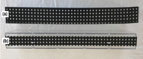
FIGURE 7. Impingement plate design impacts venting [12]. A perforated impingement plate (PIP), shown in 7a is the same width as the parting box, extending from wall to wall. A vented impingement plate (VIP), shown in 7b, has gaps between the main walls of the parting box insert and the plate (Reprinted courtesy of AIChE)
Recent tests with water using a scaled-down model of an actual parting box showed a venting issue when using a PIP [12]. Water jets exiting the sparger feed pipe entrained air upon impact with the PIP and the water above it (Figure 8). This air passed downward through the PIP and was trapped beneath it by the prevailing water head above the PIP. This air gap generated excessive froth heights above the PIP, leading to premature overflows from the box. Overflowing liquid is maldistributed and often picked up by the vapor, causing entrainment and premature flooding in packed towers [6].
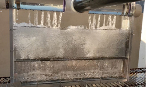
FIGURE 8. Tests were conducted with a 20% open area PIP, 4 in. above the parting box floor [12]. The liquid level at the bottom of the box was only about 1 in., with an air gap occupying the other 3 in. between the PIP and the floor of the box (Reprinted courtesy of AIChE)
Adequate venting of the PIP is achieved in some commercial designs by using a narrower impingement plate that leaves gaps on the sides to permit gas venting. Such vented impingement plates (VIPs; Figure 7b) were tested in the same test rig. The tests showed that using the VIPs with 40–50% open area completely eliminated the air gap, lowered the froth heights and eliminated the box overflow, while still providing an excellent liquid split to the parting box perforations at full rates and down to 50% turndown. The takeaway is that when perforated impingement plates are used in parting boxes, they should be well-vented. We have seen a case where overflow from a parting box containing a PIP caused a separation deterioration at high rates.
Trapping of gas by bottom sump baffles. Inadequate venting of a bottom sump baffle can cause liquid to back up above the baffle. This backup can initiate cycling or premature flooding. In one case described in Ref. 13, the base level swung by as much as 30% of its range every 10 min, resulting in bottoms flow swings between zero and 3,000 lb/h. The tower differential pressure (dP) and some temperatures also fluctuated.
Figure 9a shows the baffle arrangement at the bottom of a debutanizer tower [13]. The downcomer from the bottom tray is submerged deep within the reboiler draw sump. Liquid from the reboiler return flows to the top of the sump, under an upper sloped baffle, and then overflows a vertical baffle to reach the bottom sump. Note that the downcomer contains frothy liquid that has a lower specific gravity than the reboiler sump liquid, causing it to rise to a greater height.
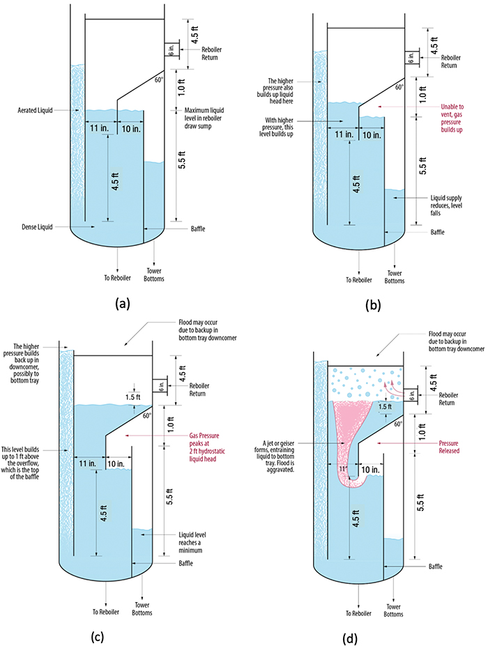
FIGURE 9. This debutanizer bottom sump cycle, detailed in Ref. 13, shows four stages: (a) initial steady state; (b) pressure buildup; (c) pressure peaks; and (d) vapor breakthrough and pressure release (Reprinted courtesy of PTQ)
Figure 9b shows the key issue. The vapor space above the bottom compartment is not vented, so vapor getting in cannot get out and will back-pressure the liquid in the reboiler draw compartment. Less liquid will overflow the vertical baffle, and the bottom level will drop. The higher pressure in the vapor space above the bottom compartment will push liquid up in the reboiler draw compartment, and its level would rise. This will also raise the backup of frothy liquid in the bottom downcomer towards the bottom tray.
This process will continue until the liquid head above the vertical baffle reaches about 2 ft, at which time the vapor space above the bottom compartment would reach the bottom of the sloped baffle (Figure 9c). The tower bottom level will reach a minimum, while the frothy liquid height in the bottom downcomer will peak, possibly flooding the bottom tray.
A vapor path now forms and the trapped vapor geysers out through the liquid (Figure 9d). Once the puff is gone, the reboiler draw compartment returns to its initial state in Figure 9a, and the process would repeat. This mechanism explained the observed fluctuations in the debutanizer.
To overcome the venting problem, the solution was to vent the bottom draw compartment using a gooseneck vent (Figure 10), and to shorten the downcomer from the bottom tray, reducing its submergence. This completely eliminated the swings.
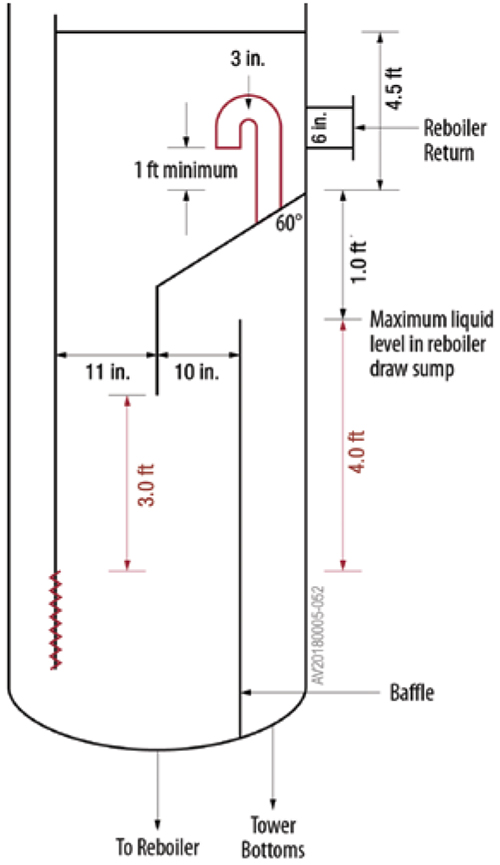
FIGURE 10. Adding a goose-neck vent allowed gas to escape from the bottoms draw sump and eliminated swings [13] (Reprinted courtesy of PTQ)
Trapping of gas in flooded reflux drums. In many total condensing systems, the reflux drums operate liquid-full and the tower pressure is controlled by manipulating the distillate rate (PC 1 in Figure 11). With the liquid-full drum, closing the valve raises the liquid level in the condenser, covering some of its heat transfer area, which in turn reduces condensation rates and raises tower pressure. Conversely, opening the distillate valve PC 1 lowers the liquid level in the condenser, exposing more tube surface for condensation, which lowers the tower pressure. Sometimes, especially in gravity systems that have no reflux pump, the reflux drum itself is omitted. Due to the absence of vapor space, the flooded drum is smaller than a drum with a vapor space, the piping is simpler, and together with the elimination of the level control offers handsome capital cost savings.
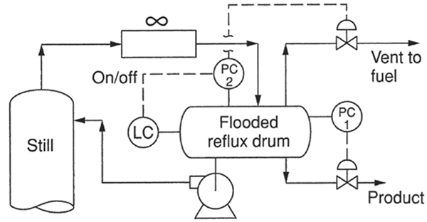
FIGURE 11. This configuration shows a flooded-drum automatic vent system that worked well [14] (Reprinted courtesy of AIChE)
Besides the condenser venting issue described earlier, the flooded drum has an additional potential venting issue. Desorption of non-condensable gases in the drum may unflood the drum and interrupt the control action. These non-condensable gases cannot return to the condenser due to the liquid leg in the line from the condenser. They need to be vented from near the top of a liquid-full drum, so the vent is likely to contain entrained liquid. The vent system and downstream need to safely handle the entrained liquid and its flash. Failure to vent these gases would render the pressure control erratic, swinging the reflux and distillate systems. If non-condensable accumulation is infrequent, manual venting from the top of the drum is often sufficient. If non-condensable gases accumulate frequently, or the column is run unattended, automatic venting is required.
Figure 11 illustrates an automatic vent system that has worked well [1, 14, 15]. A second pressure controller (PC 2), a level controller, and a control valve in the vent line are added. The set point of PC 2 is lower than that of the normal pressure controller (PC 1). When the drum is full, the level controller keeps PC2 tripped off, and the vent valve is closed. Drum unflooding (due to non-condensable gas trapping) is sensed by a drop in drum level. The lower level activates PC2. Since the setpoint of PC2 is lower than PC1, it opens the vent valve. As the pressure falls, PC1 closes, helping to build up the drum liquid level. As soon as the drum refills, the level controller trips PC2, and the vent valve closes.
Excessive gas in the tower
Issues with an excessive quantity of gas entering the tower are common, potentially troublesome, and often are unacknowledged. This is considered in detail here. In vacuum towers, there may also be issues with deficient quantities of gas entering the tower. These too are addressed.
The economic impact of non-condensable gas venting. Other than operating issues and instability in the tower, the vented non-condensable gas usually drags some product with it, which is lost. These product losses can be quite expensive, as is illustrated in the following example.
Consider a tower whose overhead product is hexane, with the reflux drum at 30 psia and 80°F. There is also some nitrogen in the drum, whether coming from the process or from a control system that adds non-condensable gas to maintain the drum (and tower) pressure. The drum pressure (Pdrum, psia) is the sum of the partial pressures of the liquid and that of the gas, given by Equation (1):
Pdrum = VPliquid + Pgas (1)
Assuming ideality and equilibrium, the partial pressure of the hexane liquid equals its vapor pressure, VPliquid, in psia. Pgas is the partial pressure of the gas in psia. At 80ºF, the vapor pressure of hexane liquid is 3.1 psia. This means that the gas partial pressure is 30 psia – 3.1 psia = 26.9 psia. On a molar basis, 10% (equal to 3.1 psia divided by 30 psia) of the vent gas at 80°F will be hexane. On a weight basis, the hexane fraction of the vent gas is higher at 26%, due to the lower molecular weight of the nitrogen. So, every ton of vent gas contains 0.26 tons of hexane. This vented product is likely to be lost, and may increase flaring or emissions. The non-condensable gas, even nitrogen, can be absorbed into the product, and can later increase pressure in downstream equipment, resulting in more product loss and flaring downstream, as discussed below.
To minimize the losses of product in the vent, the vent gas is sometimes chilled, often in a knock-back condenser, and the condensate recovered. Even cooling by as little as 20°F (to 60°F), which can be achieved with cold water, would reduce the liquid hexane vapor pressure to 1.8 psia. It would also would reduce the hexane content of the vent gas from 26 wt.% to 16 wt.%, almost halving the product loss in the gas.
Gas absorption by feed or reflux drum liquid. This mechanism is one of the most common, yet unappreciated, sources of wasteful venting. It is often inconceivable to think that a gas like nitrogen or fuel gas can be absorbed in significant quantities by process liquids. Given enough contact surface, the relatively small quantity absorbed can become significant, turn into a major economic loss, and generate environmental issues and tower instability, as described below.
Nitrogen was used to maintain pressure in a newly added debutanizer feed drum (Figure 12). Following restart, it was observed that much of the nitrogen ended up in the downstream plant. The plant needed to do considerable venting from the downstream debutanizer, deisobutanizer and depropanizer. The nitrogen got into all of these towers. The plant operators also noticed that the nitrogen control valve was opening almost fully, suggesting that a lot of nitrogen was coming in. This nitrogen had to get out, and the only open route is with the drum outlet liquid.
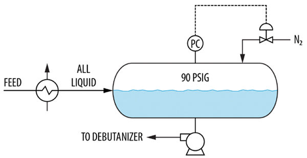
FIGURE 12. Here, nitrogen is absorbed by the liquid in a newly added debutanizer feed drum
The high absorption rate was due to the feed entry near the liquid surface. This exposed extensive contact area between the feed liquid and the nitrogen in the drum vapor space. The way to avoid this is to pipe the feed liquid to discharge near the bottom of the drum, so the entering liquid has no contact with the vapor space. The only contact area between the nitrogen and the liquid is then the stagnant surface, that will reach saturation and, as long as it remains undisturbed, will not absorb additional nitrogen.
A possible “band-aid” solution would have been to raise the liquid level, but this was undesirable because the feed frequently fluctuated, so the level was controlled at 50%. Other temporary solutions would be to keep the feed warmer or reduce the drum pressure, which the plant did until a permanent solution could be implemented.
In another tower, a split-range pressure controller on the reflux drum would either bring fuel gas in or vent gas to the flare (Figure 13). The valve adding fuel gas was always widely open and the valve to the flare closed, which was desirable to minimize flaring. The wide opening means that a significant quantity of fuel gas was absorbed by the drum liquid. The pressure control kept the drum pressure steady, but the tower pressure would swing by as much as 7 psi.
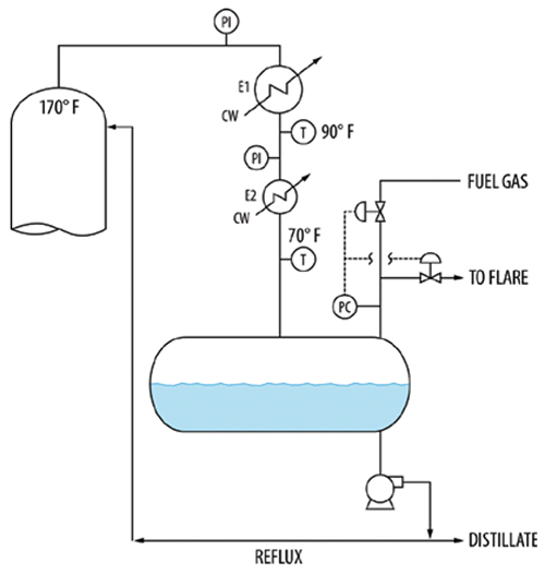
FIGURE 13. Fuel gas absorbed by the liquid in a reflux drum causes pressure fluctuations in towers and condensers
The tower overhead at 170ºF was totally condensed in exchanger E1, with an outlet temperature of 90ºF, then subcooled by exchanger E2 to 70ºF. The pressure drop across the condensers varied between 3 and 15 psi depending on the rates. As the rates increased, the pressure drop across each exchanger would rise, reaching as high as 7 psi across each exchanger. The high exchanger pressure drops, especially in subcooler E2, could only be explained by the presence of gas.
The subcooled liquid entry (by splashing onto the drum surface) would generate a large surface to absorb the gas. This gas exited in the drum liquid. Some ended in the distillate product, the rest was refluxed. In the tower, the gases absorbed in the reflux stream were desorbed, and gas blanketed the condenser and subcooler, causing the high and fluctuating dP that destabilized the tower pressure control.
A solution would be to extend the condensate pipe to near the bottom of the reflux drum. This would shield the condensate from the fuel gas and mitigate the absorption of fuel gas. The only absorption would take place right at the drum surface. As long as the surface remained undisturbed, it would quickly become saturated and there will be little additional fuel gas absorption.
Deficient or variable gas quantity
Tower design is usually based on a range of expected quantities of non-condensable gases entering the tower. When the actual quantity deviates from the design, the control system may not keep up with it, causing swings or other major operation issues. Theunick’s statement in Ref. 18 — “Effectively managing the vapor inventory is the key to controlling the pressure” — summarizes this issue.
According to Equation (1), when the product vapor pressure, VP liquid is low, and at the same time there is not enough non-condensable gas to keep the pressure Pgas high, the drum pressure, Pdrum, will fall, at times below the desired setpoint on the pressure controller. Lowering the controller setpoint reduces tower pressure, raising vapor velocities in the tower, which in turn may induce premature flooding or entrainment, possibly limiting tower capacity. Attempting to keep the controller at the higher (desired) setpoint may induce cycles of accumulating and discharging the little non-condensable gas that is present. The swings can be severe — in one case described in Ref. 18, tower pressure cycled by 20% every 6 min, inducing temperature swings as high as 90ºF, temperature inversions and off-specification product. The problem was generated by the absence of a low-boiler, which acted as a non-condensable gas. The problem was solved by adding nitrogen downstream of the condenser to increase Pgas.
Another superb illustration of this issue is in the vacuum tower described by Van der Merwe in Ref. 17. Figure 14 is a simplified diagram of the tower based on Ref. 17. The tower had an internal large dimple plate condenser (E-1) using a treated condensate stream referred to as warm tempered water (WTW) entering at 130ºF, and a smaller internal dimple-plate inerts cooler (E-2) using colder WTW (95ºF), with 1/20th the duty of E-1. The main pressure control on the tower was by manipulating the WTW rate from E-1. In case of excess pressure, the inerts flow to the vacuum system would be increased by the other pressure controller. The operator had the ability to manipulate the flow of inerts to the vacuum via the HC.
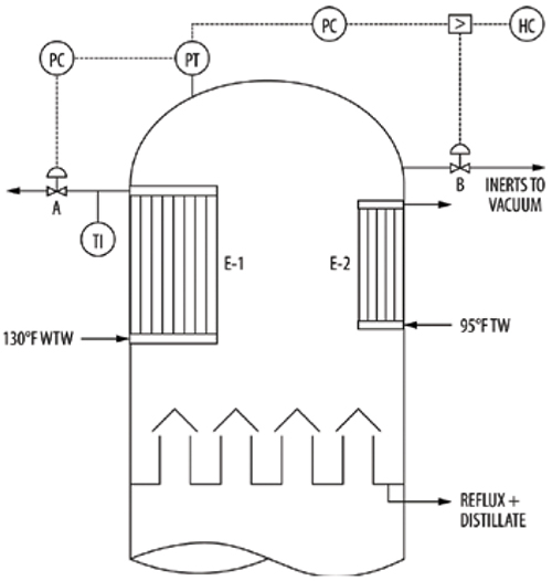
FIGURE 14. Based on Ref. 17, a vacuum tower is shown that experienced severe pressure-control problems
As it turned out, the actual air ingress into the system was 1/100th of the design. For vacuum towers, the design leakage rate is usually based on the number and sizes of flanges in the system, and it appears that the construction crew did too good a job of tightening all the flanges. The absence of inerts enhanced condensation, causing the pressure to fall. To keep up the pressure, the plant cut back the WTW flowrate, but this raised the WTW outlet temperature, which reached the maximum allowable to prevent WTW boiling. This was not sufficient to bring up the tower pressure, and it ended about 6 psi below design, which limited tower hydraulic capacity.
To compensate for the lack of air ingress, a metered nitrogen purge was added to the tower. This did not work as intended, and the tower pressure experienced oscillations of±1.5 psi, causing temperature and level oscillations, probably because of the delicate balance required between the control valve characteristics and the nitrogen addition rate.
The problem was eventually solved by changing the pressure control philosophy, and adding a WTW outlet temperature control, keeping the WTW valve as open as possible, and allowing a smaller margin between the WTW outlet temperature and its boiling point. The improved control arrangement is spelled out in detail in Ref. 17.
Case 24.5 in Ref. 15 describes an analogous problem, except that the condenser used cooling water, with the condensate temperature 250ºF. At low rates, the cooling-water valve closed, inducing high outlet temperatures accompanied by severe tube corrosion and even water boiling. Fouling was not a problem because the condenser was cleaned every few weeks. In this case, adding a nitrogen purge successfully reduced condenser heat transfer, which permitted larger opening of the cooling water valve, preventing excessive temperatures.
Another example is the vacuum tower in Figure 15. This tower had a differential pressure controller (dPC) manipulating the addition of non-condensable gas to the tower overhead. A fall of the top pressure would increase the differential pressure, and the dPC would bring in gas to keep up the pressure. This worked well for years.
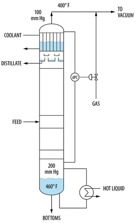
FIGURE 15. A steam leak caused pressure-control problems in this vacuum tower system
At one time, a steam leak from a service line into the tower caused major swings to occur. At the tower temperatures and pressures, the steam behaved as a non-condensable gas, greatly reducing the condenser heat transfer, as observed by a dramatic fall in the coolant level in the condenser shell. When the quantity of non-condensable gases (including steam) entering the tower exceeded the ability of the vacuum jets to remove them, the condenser became fully inert-blanketed. Condensation stopped, the product rate dropped and was lost, the top pressure drastically increased and the tower differential pressure dived.
Once the differential pressure fell, the dPC cut the gas flow to the tower overhead, helping the vacuum system remove the non-condensable gases from the condenser. The condenser was resuscitated, gradually bringing the tower pressure down. When the differential pressure returned to normal, the non-condensables rate entering the tower would again exceed its removal rate, and the cycle would repeat.
In systems similar to those in Figures 14 and 15, a high non-condensable gas rate can cause excessive upward vapor velocities in the knock-back condenser, with liquid carryover downstream. This was also reported in Case Study 24.5 in Ref. 15, and was solved by adding a valve limiter on the valve to the vacuum system (equivalent to valve B in Figure 14).
Closing throughts
Venting issues are far more common than people think. The author has often been called in to troubleshoot an operating problem, such as tower instability, poor separation or excessive product loss, which turned out to be a venting issue. The purpose of this article is to bring these venting issues to the troubleshooter’s checklist by presenting common experiences with trapped gases and how the issues were solved. Following such guidance should contribute to fewer venting issues and more trouble-free towers. ■
References
1. Kister, H. Z., “Distillation Operation,” McGraw-Hill, N.Y., 1990.
2. Bell, K. J., Coping with an Improperly Vented Condenser, Chem. Eng. Prog. 79(7), p. 54., 1983.
3. Steinmeyer, D.E., and Mueller, A. C., Why Condensers Don’t Operate as They Are Supposed To, Panel Discussion, Chem. Eng. Prog. 70(7), p. 78, 1974.
4. Standiford, F. C., Effect of Non-Condensibles on Condenser Design and Heat Transfer, Chem. Eng. Progr. 75(7) p. 59, 1979.
5. Risko, J. R., Process Optimization Allocate New Plant Focus to Steam System Design – Part 2, Hydroc. Proc., p. 49, February 2019.
6. Kister, H. Z., What Caused Tower Malfunctions in the Last 50 Years?, Trans. IChemE, Vol 81, Part A, p. 5, January 2003.
7. Lieberman, N. P., “Process Equipment Malfunctions,” McGraw-Hill, N.Y., 2011.
8. Lord, R. C., Minton, P.E. and Slusser, R.P., Guide to Trouble-Free Heat Exchangers, Chem. Eng., p. 153, June 1970.
9. Gilmour, C. H., Troubleshooting Heat Exchanger Design, Chem. Eng., p. 221, June 1967.
10. Shah, G. C., Troubleshooting Reboiler Systems, Chem. Eng. Prog., 75(7), p. 53, 1979.
11. Irhayem, A. Y. N., Purging Prevents Condenser Corrosion, Chem. Eng., p. 178, August 15, 1988.
12. Kister, H. Z., Jacobs, G. and Kister, A. A., Parting Boxes Can Make or Break Packed Tower Performance, Part 1, Perforated Sparger Feeds, Chem. Eng. Progr., p.22, May, 2021.
13. Kister, H. Z., Trompiz, C. and Clancy-Jundt, B., Troubleshooting an Instability in a Debutanizer Tower, p. 11, Revamps 2019.
14. Kister, H. Z., and Hower, T. C. Jr., Unusual Case Histories of Gas Processing and Olefins Plant Columns, Plant/Operations Prog. 6(3), p. 151, 1987.
15. Kister, H. Z., “Distillation Troubleshooting,” Wiley, N.J., 2006.
16. Stupin, W. J., and Kister, H. Z., System Limit: The Ultimate Capacity of Fractionators, Trans. IChemE Vol. 82, Part A, January 2003.
17. Van der Merwe, J., Distillation Pressure Control Troubleshooting – The Hidden Pitfalls of Overdesign, Chem. Eng. Res. Des., 89, p. 1,377, 2011.
18. Theunick, G., Composition Change Impacts Pressure Control, Kister Distillation Symposium 2019, Topical Conference at the 2019 AIChE Spring Meeting, New Orleans, La., p. 597, March 31 – April 4, 2019.
Author
 Henry Z. Kister is a senior fellow and the director of fractionation technology at Fluor Corp. (3 Polaris Way, Aliso Viejo, CA; Phone: 949-349-4679; Email: henry.kister@fluor.com). He has over 35 years experience in design, troubleshooting, revamping, field consulting, control and startup of fractionation processes and equipment. Kister is the author of three books, the distillation equipment chapter in Perry’s Handbook, and over 130 articles, and has taught the IChemE-sponsored “Practical Distillation Technology” course more than 530 times in 26 countries. A recipient of several awards, Kister obtained his B.E. and M.E. degrees from the University of New South Wales in Australia. He is a Fellow of IChemE and AIChE, and serves on the FRI Technical Advisory and Design Practices Committees.