Laminar Pipe Flow
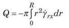
For steady flow in a pipe (whether laminar or turbulent), a momentum balance on the fluid gives the shear stress at any distance from the pipe centerline.
![]()
In Equation (1), Φ = P + ρ gz. The volumetric flowrate Q can be related to the local shear rate by doing an integration by parts of Equation (2).
Newtonian fluid. For a Newtonian fluid, τ rx = µY rx, which gives the following volumetric flowrate, known as the Hagen-Poiseuille equation.
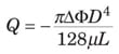
It can be written in dimensionless form in Equation (4) with the two terms defined in Equations (5) and (6).
![]()
Power law. A fluid that follows the power law model obeys the relationship τ rx = – µ(– Y rx) n. This gives the following equation.
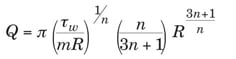
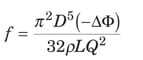
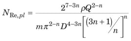
Equation (7) can be rearranged into the following dimensionless form.
![]()
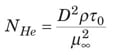
Bingham plastic. In this case, there is a solid-like “plug flow” region from the pipe centerline (where τ rx = 0) to the point where – τ rx = τ 0 (that is, at r = r 0 = R x τ 0/ τ w). The result is a flow integral modified from Equation (2). For a Bingham plastic, – τ rx = τ 0 + µ ∞ ( – Y rx). Using this expression and the modified flow integral, the Buckingham-Reiner Equation (10) is found.
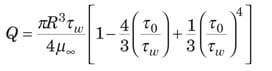
The equivalent dimensionless form is given by Equations (11), (12) and (13).
![]()
Turbulent Pipe Flow
Since most turbulent flows cannot be analyzed from a purely theoretical perspective, data and generalized dimensionless correlations are used.
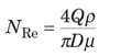
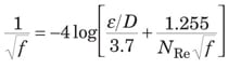
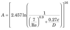
Newtonian fluid. The friction factor for a Newtonian fluid in turbulent flow is a function of both N Re and the pipe relative roughness, ε /D, which can be read off the Moody diagram [ 5]. The turbulent part of the Moody diagram (for N Re > 4,000) is accurately represented by the Colebrook equation (14).
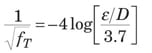
When N Re is very large, the friction factor depends only on ε /D. This condition is noted with f T as the “fully turbulent” friction factor in Equation (15).
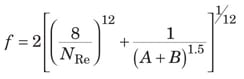
The Churchill Equation [ 2] represents the entire Moody diagram, from laminar, through transition flow, to fully turbulent flow. It is presented here as Equations (16), (17), and (18).

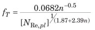
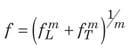
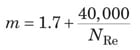
Power law. For a power-law fluid, the friction factor depends only upon Equation (9) and the flow index, as represented by Equations (19) – (25) [ 3].
![]()
![]()
![]()
![]()
The value of N Re where transition from laminar to turbulent flow occurs ( N Re,plc) is given by Equation (25).
![]()
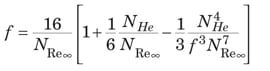
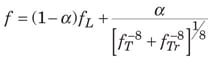
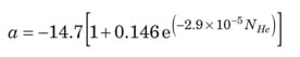
Bingham plastic. For the Bingham plastic, f T is solely a function of N Re ∞ and N He, as represented by Equations (26) – (29).

DefinitionsNewtonian fluid. A fluid is known to be Newtonian when shear stresses associated with flow are directly proportional to the shear rate of the fluid Power law fluid. A structural fluid has a structure that forms in the undeformed state, but then breaks down as shear rate increases. Such a fluid exhibits “power law” behavior at intermediate shear rates Bingham plastic fluid. A plastic is a material that exhibits a yield stress, meaning that it behaves as a solid below the stress level and as a fluid above the stress level |
Nomenclaturea Dimensionless parameter A Dimensionless parameter B Dimensionless parameter D Diameter, m f Fanning friction factor, dimensionless f L Laminar friction factor, dimensionless f T Fully turbulent friction factor, dimensionless f Tr Transition friction factor, dimensionless g Gravitational acceleration, m/s 2 L Length of cylinder or pipe, m m Consistency coefficient, (N)(s)/m 2 n Power law fluid flow index, dimensionless N He Hedstrom number, dimensionless N Re Reynolds Number, dimensionless N Re,pl Power law Reynolds Number, dimensionless N Re,plc Power law Reynolds Number at transition from laminar to turbulent flow, dimensionless N Re∞ Bingham-plastic Reynolds Number, dimensionless P Pressure, Pa Q Volumetric flowrate, m 3 /s r Radial position in a pipe or a cylinder, m R Pipe or cylinder radius, m V Velocity, m/s z Vertical elevation above a horizontal reference plane, m α Dimensionless parameter Y rx Shear rate in tube flow, s – 1 ε Wall roughness, m µ Newtonian viscosity, Pa – s µ ∞ Bingham Plastic limiting viscosity, Pa – s ρ Density, kg/m 3 τ 0 Yield stress, N/m 2 τ rx Stress due to force in x direction acting on r surface, N/m 2 τ w Stress exerted by fluid on tube wall, N/m 2 Φ Flow potential, P + ρ gz, Pa âˆ†Φ Increase in flow potential, Pa |
References
|