There are many factors to consider when selecting a flare system for CPI sites that can impact safety, operating costs and environmental performance
Flaring has long proven to be an effective technology for disposing of gases that cannot be used otherwise. Different flaring techniques are utilized in the chemical process industries (CPI), depending on environmental regulations, site requirements and process needs. Different flare technologies offer tradeoffs among equipment cost, operating expense, design complexity and process requirements. Selecting the proper flare equipment can result in optimized capital and operational costs while maintaining compliance with environmental requirements. Before a flare type is selected, it is important to understand the environmental impacts, process requirements and economic considerations of a particular operation or project. Improper application of a flare technology can lead to not only poor performance, but also negative environmental impacts, which can later result in significant costs and legal implications. This article provides details of the different types of flares used at CPI sites and their selection criteria.
Flare design
A flare is a device used to safely dispose of unwanted or excess gases and liquids from normal, unplanned or upset conditions during process operations in CPI sites. Flaring is done by burning off the gas or liquid into the atmosphere. The gases or liquids to be combusted are usually rich in heat content, enabling them to self-sustain the combustion without the need for additional external combustion gas.
A typical flare consists of a gas inlet connected to a flare header. Combustion is achieved through an ignition device located at the ground level and a pilot burner tip located at the top of the flare header. The gas to the pilot is usually provided from a utility source. A water seal or purge-gas arrangement is used to prevent any flashback into the process stream. A flare usually generates water vapor and CO 2, which are discharged into the atmosphere.
Flare types
Flares are classified into two common types: elevated and ground flares. Elevated flares are the most widely used flare type in CPI sites. In elevated flares, the gases are combusted using flare headers that are located at a considerable height above the ground. Elevated flares are again classified into several types, depending on the type of gas, the incoming gas pressures, smoking or non-smoking requirements, heat radiation levels and location. Elevated flares have an open flare associated with them. An open flare consists of a visible flame that generates heat and some noise.
Ground flares are systems where the combustion of the gases takes place at the ground level. Since these flames are close to the ground, they have to be enclosed in a refractory-lined chamber or enclosure. As combustion takes place at the ground level, gases are released close to the ground, resulting in poor gas dispersion. Due to these limitations, enclosed ground flares are commonly used in situations where the gases to be burned are relatively clean and when reducing noise pollution is critical.
Elevated and ground flares used at CPI sites can be further classified into two types: single-point and multi-point flares. Single-point flares are typically oriented to fire upwards. Single-point flares can be smokeless or non-smokeless using air-assisted or steam-assisted designs, and are suitable for low-pressure applications. Multi-point flares are designed for higher-pressure applications and where smokeless burning is required. Multi-point flares are used to improve the burning by applying multiple burning points. These can be located on the ground level or at an altitude using boom supports.
Single-point elevated flares
Utility flares.These are elevated flares that are commonly used for low-pressure natural-gas flaring. They are used for non-smokeless flaring of heavy hydrocarbons present in gas streams. They are mostly emergency-only flare systems. Their key design features a double-thick flame-retention ring and they work with all types of ignition systems.
Air-assisted flares.These flares are also elevated flares used for smokeless flaring of heavy hydrocarbons. They are commonly used where low-pressure waste gas is present. Air-assisted flares (Figure 1) use air to surround the gas during the combustion. The air removes the smoke that is present when burning off heavy hydrocarbons. The flares’ design features multiple flare-tip devices with a large air-fuel boundary in the enclosure.
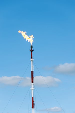
FIGURE 1. Air-assisted flares are a type of elevated flare where air is used to remove the smoke produced from burning off hydrocarbons
Steam-assisted flares. This type of elevated-flare system utilizes steam to remove the smoke generated upon combustion of heavy hydrocarbons. They are very similar to air-assisted systems, except steam is used instead of air.
Sonic flares. Sonic flares are typically used when the gas to be flared is under high pressure. Smokeless flaring of heavy hydrocarbons at high pressures is done using these types of flares. Sonic flares usually operate at Mach 1 speeds. They are associated with lower stack heights due to the high velocity requirement. Low radiation is required for such applications.
Portable flares.Portable flares are used in situations where a vessel or a tank needs to be evacuated for maintenance purposes. They are also used as temporary flares during a facility shutdown or when bypassing of the main flare is required.
All types of flares require some sort of structural support, due to the height requirements. The commonly used flare supports for onshore applications are guyed wires, freestanding and derrick support types. Some of the derrick support types are demountable for maintenance purposes. Permanent boom structures used in production flares are arranged at a 15–45 deg angle from horizontal.
Multi-point flares
Multi-point flares (Figure 2) are used when improved burning performance is required. Here, the gas stream is divided into multiple streams and into multiple burning points. They can be arranged near grade or in elevated booms. For CPI sites, multi-point flares are designed to achieve smokeless burning.
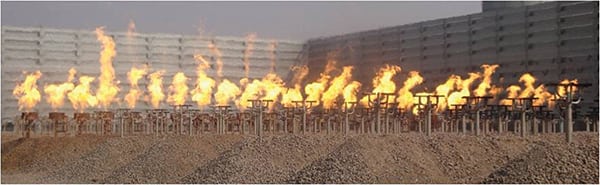
FIGURE 2. Multi-point flares divide the gas stream into multiple streams and burning points
Enclosed ground-flare systems
Enclosed flares (Figure 3) are installed in situations where flame visibility is unacceptable. They feature flares at the ground level and come into play when measuring flare emissions is required. The gases treated are typically low-flow and low-pressure exothermic waste streams. These flares are required in areas where heat radiation must be kept to a minimum. Enclosed flare systems come in both natural and forced-draft types. Usually, the combustion chamber is a steel structure lined with refractory material. Most of the units are temperature-controlled with sample ports available for measurements.
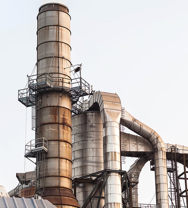
FIGURE 3. An enclosed flare is a useful option when measurement of emissions is required
Safety considerations
The primary safety concern for flares is thermal radiation. Special consideration must be given to thermal radiation for flares that are located close to the boundaries of CPI sites. Safety regulations must be followed by plant operators to ensure that flares are operated in safe zones in a responsible manner. Often, the safest operations can be accomplished by increasing the flare height or putting up restrictions (such as signs or barriers) denoting the area as a low-access area. Enclosing the flares is another way of limiting radiation in plants that have limited area for use.
Smokeless flares are sometimes desired in areas that are environmentally sensitive. Air-assisted or steam-assisted flaring is utilized in such instances to convert the flares to smokeless flares. Combustion gases from flares that mix with indoor air can cause serious problems when inhaled. Therefore, adequate ventilation is required in facilities that are located close to flares. Companies must assess the toxicity of the gases that are being emitted and implement appropriate measures if there is a health risk if these gases are inhaled.
Noise pollution is another safety concern when flaring of gases occurs. Workers or personnel exposed to the noise over a continued period of time have experienced hearing loss or other auditory problems. Companies must provide personal protective equipment, such as ear plugs or other protection, for prolonged exposure to the noise generated by flares.
Finally, it is imperative for companies to engage in emergency planning and prevention measures in case of any flare malfunction. The potential risk to workers in the event that a flare does not function properly is a serious safety concern. Regular maintenance is required to ensure that the flares are functioning properly, and that there is always a backup plan in case of such emergencies.
Design plays an important role in the safety of flares. Some of the key parameters that need to be considered while designing a flare include spacing, location, height, capacity and flashback.
Radiant heat can be minimized if the flare is located at a safe distance from buildings and office spaces. Therefore, it is important to have enough space available in case of any mishaps. Flare height is also an important safety design consideration. The height of the flares must be such that it prevents any burnt material from falling down onto the ground. Also, height is taken into consideration during air-dispersion modeling studies to prevent hazardous materials from entering breathing air.
Flare capacity must be sized so that it is large enough to handle gas releases from relief valves, emergency systems and blowdowns from different processes. Improperly sized flares can lead to flare damage and can also cause explosions. Finally, flashback is a situation where flames can travel back into the process piping. To prevent flashback, flares are designed with water seals or purge-gas systems.
Flare performance
Flares usually operate at a combustion efficiency of 98% for converting organic compounds to CO 2 and water vapor. Greater than 98% efficiency is achievable if the flares are properly designed. The key parameters to measure the performance of flares are the following:
- Thermal radiation
- Smokiness using the Ringelmann smoke chart (Figure 4)
- Flame intensity
- Combustion efficiency
- Emission levels
- Noise levels
- Pilot flame stability
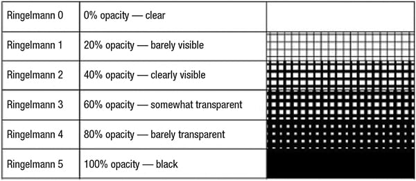
FIGURE 4. The Ringelmann Smoke Chart measures the smokiness of a flame, which helps to quantify flare performance
The following paragraphs provide details on testing methods used to measure flare performance.
Ringelmann chart.A Ringelmann chart is commonly used to measure the smokiness of a flame. The Ringelmann scale, as shown in Figure 4, ranges from 0 to 5, based on the level of visibility. Flares that have a good performance usually range in the lower scale values. A black flame with a scale of 5 indicates a very smoky flame. A clear flame with a scale of 0 indicates a fully smokeless flame.
Thermal radiation.Thermal radiation is measured using sensors and radiant heat-flux monitors. These usually give a measure of either the solar and flare radiation combined or just the flare radiation levels alone.
Flame intensity.Flame intensity and lengths are measured using flame intensity monitors. These devices use single-wavelength sensors to detect flame intensity and also have capabilities to measure flame lengths.
Combustion efficiency.With recent technological advancements, combustion efficiency is now measured using Fourier transform infrared (FTIR) methods. FTIR uses remote-sensing technology to detect combustible products, such as carbon dioxide, carbon monoxide and select hydrocarbons. Conventional, non-FTIR measurement techniques rely on calculations using derived carbon-balance and tracer-injection methods.
Emissions levels.Emissions levels from flares are difficult to determine. This is because flares do not contain emissions after combustion has taken place. Typical methods to evaluate emissions are inferred measurements, which take into account the amount of gas flared, along with emission and oxidation factors.
Noise levels.Noise levels are measured using noise meters at different points in the flare. Noise levels are classified as sound pressure levels or sound power levels as functions of either pressures or flowrates.
Pilot flame stability.Pilot flame stability is usually tested using scanning devices, such as ultraviolet (UV) scanners. The stability of pilot flames is important to monitor because it keeps the flare burning and indicates reliable operations.
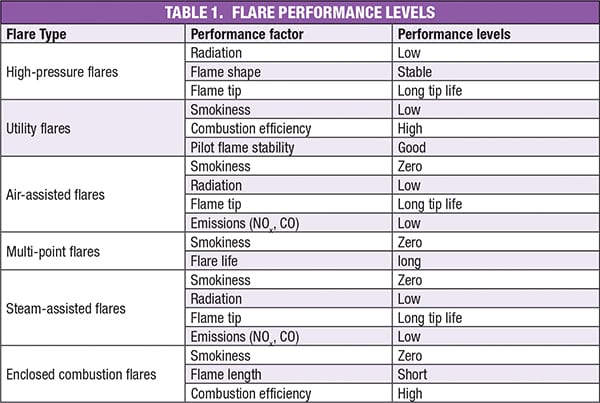
Performance expectations
Table 1 shows what performance levels are to be expected for different types of flares.
With all the different performance factors that can influence the selection of a flare system, it can be difficult to determine where to start the process of designing and selecting a flare technology. By evaluating the design considerations discussed in this article, engineers can assess the available technologies and the performance expectations of each flare before beginning the flare selection process. Selecting the right flare is critical for the overall design of a process from the safety, environmental, economic and social impact point of view. The correct flare choice will ensure that the flare can meet its objective, which is safely disposing of waste gases and liquids into the atmosphere. ■
Edited by Mary Page Bailey
Author
 Anu D. Vij is chief operating officer (COO) of Ship & Shore Environmental Inc. (2474 N. Palm Drive, Signal Hill, CA 90755; Phone: (562) 997-0233; Email: [email protected]; Website: www.shipandshore.com). Vij has over twenty years of experience in the environmental, chemical, petrochemical and air-pollution-control industries, and has specific expertise in thermal oxidation technologies. As COO at Ship & Shore, he oversees several business units, including Sales, Finance, Engineering, Project Management, Procurement, Production and Services. Prior to joining Ship & Shore, Vij served as vice president, enclosed combustion systems, at Aereon and was director of engineering at OnQuest Inc. Vij holds an M.S.Ch.E. from the University of Southern California and a B.S.Ch.E. from Panjab University in India.