Many branches of the chemical process industries (CPI) make use of impact comminution to process solid matter, such as minerals, foodstuffs, pharmaceutical products, and above all, products for the chemicals industry. Impact comminution is also used for coarse crushing, but the focus of this article is fine grinding with end-product particle sizes below 500 µm. The technology of impact comminution is, however, not particularly popular with the users of impact grinding systems because it is energy-intensive, associated with a high noise level and frequently also gives rise to time-consuming maintenance work. In spite of this, impact comminution is still the most cost-effective solution in many processing operations.
The fundamentals
With every method of comminution, one has to generate a level of stress in the particles that is so high that the particles fracture as a result. Beside other methods, this stress can be generated by pressure (compression) or impact (Figure 1). In the case of compression, the particle is stressed between two solid elements, whereas in the case of impact comminution, the particle is in contact with only one other element at the moment of fracture, either an impact plate or another particle.
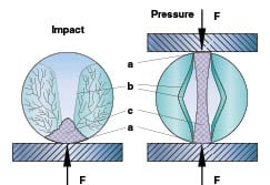
Figure 1. Fragmentation of glass beads is achieved by either impact or pressure (F = force; a = contact area; b = cracks; c = fines)
A prerequisite for impact comminution is brittle-elastic material behavior. Materials scientists call a material brittle-elastic if deformation of the sample is initially proportional to the applied stress and the fracture occurs suddenly (Figure 2). The dark area under the plotted line is equivalent to the work that is necessary to deform the particle. With impact comminution, the kinetic energy of the particles is employed to generate the requisite degree of deformation. In the linear range, the deformation is elastic and reversible. As soon as higher stresses occur, the material strength is exceeded locally and cracks are triggered. The cracks grow extremely quickly and lead to destruction of the particle.
Equipment has been built for scientific experiments in which individual particles are subjected to one single impact under defined conditions. From these single-particle impact tests the following three things are known: that a minimum fracture energy must be applied to the particles, that the probability of fracture is dependent on the kinetic energy and that the resultant particle-size distribution is dependent on the properties of the material being processed.
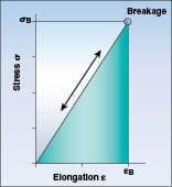
Figure 2. This stress-strain curve shows the behavior of brittle-elastic materials
According to theory, a speed multiplication of 5.6 would be necessary to double the stress in the particles. In other words, increasing the impact speed has only a limited influence on the expected fineness. On the other hand, the impact speed is the only parameter with which it is possible to effectively change the stress condition in a particle, which is why impact mills usually run at high peripheral speeds of up to 150 m/s. When two rotors are driven to rotate in opposite directions, relative speeds of up to 250 m/s can be achieved. In jet mills, compressed gas is expanded in Laval nozzles. At common gas pressures and temperatures, the exit velocity of the gas jets is around 500 m/s.
As Figure 1 shows, a single fracture event leads to a number of coarse fragments but to relatively little fine product. Because of this, the aim is multiple stressing of the particles in mills in order to obtain a fine end product. One can assume that a feed material is subjected to between 5 and 20 impact events in simple rotor impact mills. With fine grinding, air classifiers can be integrated into mills that allow only those particles with the desired end-particle size to pass through the classifying wheel, but which return coarser particles for final grinding. For jet mills, up to 100 stressing events can be necessary to grind the feed material to high fineness values if it is of poor grindability. The number of stressing events is therefore a parameter that has a greater influence on the product fineness than the stressing speed.
The particle size distribution of the ground product is a function of the mill parameters, stressing frequency and stressing intensity, as well as the feed material characteristics. Today it is not possible to accurately predict the result of a comminution trial with an impact mill based on scientific principles. This applies to particle size distributions and to the specific grinding energy.
Feed material requirements
If impact comminution is to be economically viable, the feed material must fulfill a number of general requirements. In the case of fine impact mills, there is a maximum feed size that must not be exceeded if the mill is to remain undamaged by any large lumps in view of the high peripheral speed. A particle size of 5 to 10 mm can be assumed as the maximum, whereby the faster the rotor rotates, the finer the feed material should be. Tramp material must be removed from the feed material.
Mechanical impact grinding can be used on materials with a Mohs hardness of up to 3–4 (see Table 1). But even small amounts of harder components in the feed material can lead to an uneconomical degree of wear. When grinding natural gypsum — which is actually soft — a few percent of quartz in the feed will make it necessary to exchange the wear plates in the mill frequently. The same or similar phenomenon applies to vegetable products that are contaminated with sand. In the case of especially fine feed materials, harder materials can also be processed, provided that the wear protection in the mill is well adapted to the product properties.
| Table 1. Mohs’ scale of hardness | |
| 1 | Talc |
| 2 | Gypsum |
| 3 | Calcite |
| 4 | Fluorite |
| 5 | Apatite |
| 6 | Orthoclase |
| 7 | Quartz |
| 8 | Topaz |
| 9 | Corundum |
| 10 | Diamond |
The feed material should not be heat-sensitive, that is, the softening or melting point has to be above 70°C if the material is to be ground in a mechanical impact mill. The reason is that the energy of the motor is converted almost completely into heat, and mills and systems heat up to 50–60°C under full load. Heat-sensitive products can be processed only by cooling the feed material or the mill air, or both, which ultimately means additional energy costs.
Liquid components in the feed material can also have an extremely disruptive effect. The product should be dry, with the maximum moisture content of normally only a few percent. If liquid is released during comminution, this frequently leads to the formation of build-up. This also applies to feed material that contains oil or fat.
Besides the specifications related to the particle size distribution, the product properties mentioned here play a major role in the selection and design of impact mills. For this reason, trials are always carried out with a test system for new applications.
Machine types for fine grinding
Rotor impact mills have been in use for over 100 years. As a result of the wide range of feed products, a great number of different machine types have established themselves on the market during this time. Jet mills, which operate with a gaseous medium, have also been on the market for a long time. In this article, only a few of the widely available machine types can be described.
Mechanical impact mills. Simple impact mills consist essentially of a high-speed rotor. Fine particles follow the flow of air in the mill after extremely short acceleration paths. Because of this, the clearance between rotating and stationary grinding elements should only be a few millimeters. Characteristic for fine impact mills are a high-speed rotor and stationary grinding elements located in its immediate proximity. The grinding zone can be disc-shaped, in which case the product is fed centrally and the feed material migrates in radial direction across the disc, just as with the pin mill. The grinding zone can also be cylindrical, in which case the feed material migrates along the cylindrical surface through the mill. The transport of the material can take place against the force of gravity, in the direction of the force of gravity, or even at right angles to it. In addition, impact mills can be equipped with a classifying discharge, for example sieves, screens or classifying wheels. The design most suitable for a given application must be determined during the course of trials.
Classic rotor impact mill. These machines are characterized by a flat-cylindrical, vertically upright housing and a horizontal shaft supporting the rotor (Figure 3). These machines have a big door, which can be easily opened for maintenance of the grinding equipment. The product is fed to the center of the rotor and exits in ground condition at the periphery of the mill. Air flowing through the mill assists transport of the product and cools the machine and product. The high-speed rotor with impact elements grinds the feed material and assists the transport of the air, in a similar way to a radial fan. The fineness is set as a function of the rotor speed and the product throughput. Higher throughputs lead to a coarser product, which is attributed to increasingly ineffective particle-particle impacts. The feed metering unit is controlled by the current loading of the mill motor.
Sieve inserts with various kinds and arrangement of perforations have the benefit of top-size control, but are always more prone to wear. Sieves can only be employed down to a minimum aperture size of approximately 0.5 mm. The design shown in Figure 3a is therefore suitable for coarser grinding tasks. In the fine range and with coarse feed materials, grinding tracks are used. Grinding tracks usually have an annular discharge gap for the ground product. In the case of the plate beater unit (Figure 3b), exchangeable impact plates permit the processing of mildly abrasive materials. At high speeds and low throughputs and in combination with a grinding track, fine products are achieved. When employed in combination with a grinding track or sieve ring, or both, the plate beater unit is suitable for fine grinding, defibration, chipping and deglomeration.
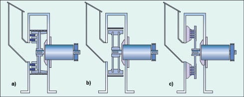
Figure 3. Simple rotor impact mills with crushing rotor and sieve (a), with plate beater unit and grinding track (b) and with pin discs (c)
With pin discs (Figure 3c), comminution takes place between the rotating and stationary concentric rows of pins. The diameter of the pins and the pitch diameter for the pins are geared to each other such that particles cannot flood through the pin rows. The fineness is regulated as a function of the speed. The principle of multiple stressing is implemented in this mill in an extremely graphic manner: the particles have to pass through every row of pins before they are able to exit the mill and impact against many pins in the grinding process. The narrow gap between the rows of pins ensures high impact speeds, even for fine particles. Tramp material in the feed material is a risk to the relatively fragile pins and can cause a lot of damage.
The largest mills of this type have rotor diameters of some 1.5 m and a drive power of up to 315 kW. The maximum peripheral speeds reach 150 m/s. The maximum fineness that can be expected for simple impact mills is, for many products, around 100 µm. When reference is made in this article to the product fineness but is otherwise not specified, this is understood as the cumulative undersize of the particle size distribution of 97%. Table 2 shows some applications for simple impact mills.
| TabLE 2. Applications for simple rotor impact mills | |||
| Pharma/Food | Chemicals | Minerals | Other |
| Sugar | Fertilizer | Natural gypsum | Wood shavings |
| Lactose | Paint | FGD-gypsum | Cork |
| Casein | Pigments | Limestone | Fodder |
| Herbal tea | Salts | Chalk | Recycling |
| Starch | Silicates | Used paper | |
| Gelatine | Wax | Tobacco | |
| Spices | Resin | ||
| Hibiscus | Stearate | ||
| Sage | Sulfates | ||
| Rose hips | Phosphates | ||
| Active pharmaceutical ingredients (API) | Plastics | ||
| Cellulose derivatives | |||
Pin mills with two rotating pin discs (disintegrators). The basic design of this machine corresponds to that of the classic, fine impact mill, although here, both pin discs are driven separately (Figure 4). The fineness of the end product is set as a function of the peripheral speeds of the counter-or co-rotating pin discs. The relative speed of the outside row of pins can reach up to 250 m/s. Compared with the simple, fine impact mill, the counter-rotating pin mill achieves significantly higher fineness.
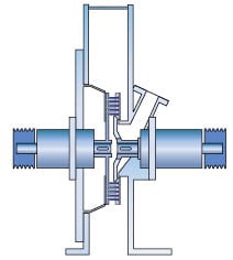
Figure 4. A pin mill with two rotating pin discs
The use of two rotating discs reduces the formation of deposits on the pins in comparison with pin mills equipped with one stationary disc or mills with grinding tracks. This can be accomplished by a generously dimensioned housing, the so-called wide-chamber housing. Therefore, this machine is especially suitable for the grinding of sticky feed material. Applications for this machine type are given in Table 3. The largest pin mill of this type ever to be built has a pin disc diameter of approximately 1.1 m and a drive power of 500 kW.
| Table 3. Applications for pin mills with two rotors | |||
| Pharma/Food | Chemicals | Minerals | Other |
| Spices (cryogenic grinding) Cacao press cakes | Paints Pigments Stearate Plastics (cryogenic grinding) | Chalk Limestone Coating of limestone | Proteins Rubber (cryogenic grinding) |
Long gap mills. In contrast to the classic, fine impact mill, the rotor here is vertically arranged (Figure 5). The feed material is charged from below, entrained in the transport air and is conveyed pneumatically through the grinding zone, but can also be fed to the lower area of the grinding zone. The grinding zone extends over the entire cylindrical area between the rotor beaters and the peripheral grinding track. The product must travel all the way along this gap, which is longer compared with other mills. Mills of this type are therefore called long gap mills, although the name air vortex mill is also known. This name, however, implies that comminution is the result of particle-particle impacts in an air vortex. Because an efficient fine-grinding operation necessitates unhindered impact of the particles on the grinding elements of the mill, grinding in air vortices can only be a minor effect. The fineness in this mill is also set by the rotor speed and the throughput of the feed material.
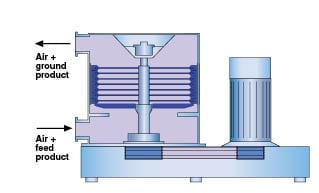
Figure 5. In long gap mills, the rotor is vertically arranged
The rotor of the long gap mill consists of grinding stages located one on top of the other and separated from each other by discs. Each grinding stage is equipped with a number of impact plates. Exchanging the many impact plates is time-consuming, which is why machines are now available that are equipped with continuous impact bars that can be exchanged easily. The rotor is surrounded by the grinding track, which is composed of grooved grinding track segments. An air classifier can be installed above the grinding zone. The classifier, however, does not make a real classifier mill out of the long gap mill, because the recirculation of the coarse material upstream of the grinding zone is complicated.
The long gap mill is especially suitable for simultaneous grinding and drying. (Further applications are given in Table 4.) This is due to the fact that there are no dead zones in which the moist product could cake and deposit. Long gap mills are operated at peripheral speeds of up to 150 m/s, and can grind finer than the simple impact mill as a result of the higher number of stressing events. They can also produce steeper particle size distributions as a result of a narrow residence time distribution. The largest mills of this type have rotor diameters of over 2 m and a drive power of over 1,000 kW. Large long gap mills are by far the largest fine impact mills.
| Table 4: Applications for the long gap mill | ||||
| Food | Chemicals | Minerals | Other | |
| Fine grinding | Cereals Vegetables Soya Fish meal Starch Fiber Bran Thickener | Pigments Paints Carbon black Titanium dioxide Plastics Iron oxide | Gypsum Coating of limestone | Wood PVC Rubber Polyurethane foam |
| Impact drying | Proteins Starch Lactose Casein | Cellulose derivatives Titanium dioxide Pigment suspensions Press cakes | PCC (precipitated calcium carbonate) suspensions Gypsum Aluminium oxide | Blood products PVC filter cakes |
Fine impact mills with air classifiers. Because the grinding elements and an air classifier are integrated into a single machine housing, this type of mill is known as a classifier mill. With classifier mills it is the integrated classifier that controls the product fineness and not the speed of the grinding rotor. Classifier mills thus offer the advantage of the highest finenesses among the mechanical impact mills and stable product properties even if the properties of the feed material are changing. These reasons are the motivator behind the increasing use of classifier mills. However, these advantages give rise to higher costs because a more powerful fan is needed than with the simple rotor-impact mills. The fan sucks the transport air through the mill against the resistance of the classifying wheel. The pressure drop at the classifying wheel can be several thousand Pascals. The feed rate is usually controlled with the current of the mill motor.
A schematic of the most-widespread classifier mill is shown in Figure 6. The maximum peripheral speed of these mills is up to 150 m/s; the air classifiers run at peripheral speeds of up to 60 m/s. This mill type has been on the market since about 1970 and is built in over 20 machine sizes. The largest mills have a drive power of up to 500 kW.
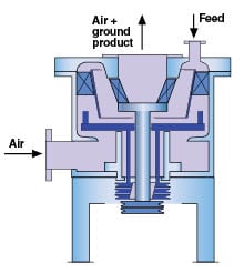
Figure 6. Classifier mills achieve the highest fineness among mechanical impact mills
The grinding disc is driven from below via a hollow shaft. The shaft for the conical deflector classifying wheel, which has its own frequency-controlled drive, runs through the hollow shaft. The feed material is charged pneumatically, for which a partial flow of the mill air has to be branched off. Comminuted material follows the flow of air around the guide cone to the classifying wheel. The high-speed classifying wheel allows only fines to pass through it; coarse material is rejected and returned to the grinding disc where it is reground. The cover for the machine can be hinged back so that internals are easily accessible for cleaning.
Dictated by their function, deflector wheels cannot be set to any coarse value desired, but are limited to a top value of around 200 µm (assuming a feed material with a bulk density of 2,000 kg/m3). At high speeds, classifier mills compete with jet mills, and at coarser fineness values, also with pin mills. Compared with jet mills, the energy consumption of the classifier mill is comparatively low, and compared with pin mills, it has advantages in terms of operating stability, an exact top cut and a higher resistance to wear. Over the course of the years, a number of different classifier mills have been developed, each of which have their strengths for certain applications (Table 5).
| Table 5: Applications for classifier mills | |||
| Pharma/Food | Chemicals | Minerals | Other |
| Cacao press cakes Sugar Lactose Vegetable products Gelatine Alginate | Powder coating Paints Pigments Silica Resins Wax PVC | Limestone Talc | Proteins Wood Sodium bicarbonate |
Jet mills. In combination with an air classifier, jet mills deliver the highest finenesses as a result of the high impact speed and multiple stressing of the feed material.
Jet mills use the effect that compressed gas is accelerated to extremely high speeds when it is expanded in a nozzle. Thereby, the energy contained in the compressed gas in the form of heat is converted to kinetic energy. The gas can even be accelerated to supersonic speed in a Laval nozzle. A Laval nozzle is characterized by its hourglass shape, which widens downstream of the narrowest diameter in a similar way to Venturis.
Compressed air at 20°C and between 6 and 8 bar overpressure is frequently used, in which case the exit velocity of the air is approximately 500 m/s. If the product permits, the compressed air is not cooled downstream of the compressor, and jet mills are operated at elevated temperatures. Air velocities of approximately 600 m/s can be achieved in this way. After exiting the nozzle, the speed of the jet drops rapidly as a result of air and product being sucked in from the surroundings.
If superheated steam is used as the propellant, it is possible to achieve speeds of over 1,000 m/s. A significant disadvantage of grinding with steam, however, is the tricky operation of a system where the risk of condensation in the downstream filter is high. This is the reason why more and more jet mill owners have meanwhile switched from steam operation to compressed air mode.
Increasing demands on the product quality and the development of the fluidized-bed opposed jet mill (described below) have helped jet milling gain acceptance, even though the energy consumption of jet mills is extremely high. Besides taking a look at the fluidized-bed opposed jet mill, the spiral jet mill, which continues to be popular in the pharmaceuticals industry is also considered.
Spiral jet mill. The spiral jet mill is a simple piece of equipment. At the periphery of the flat-cylindrical grinding-classifying chamber, compressed air is expanded in nozzles that are pitched at an angle of between 30 and 50 deg. to the radius (Figure 7). This causes a rotating air stream in the grinding chamber. The feed material, charged to the grinding chamber through an injector, becomes caught up in the rotating flow of air, is centrifuged and ultimately forms a rotating ring of material at the periphery. This transports the feed material into the jets of grinding air, where it is comminuted mainly as the result of impacts between the particles traveling at different speeds. The air stream in the grinding chamber effects a spiral classification: fine material is conveyed to the central discharge opening, whereas coarse material is centrifuged back out to the periphery. A high pressure builds up in the mill as a result of the air rotating at high speed. This makes it necessary to use an injector operated with compressed air to feed the material; with approximately 30%, the injector requires a considerable share of the total air flow.
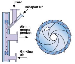
Figure 7. The spiral jet mill is relatively simple
The spiral jet mill has no fineness control. At a constant air flowrate, the feedrate is the main parameter used to adjust the fineness. A high throughput results in coarse product because the spiral is decelerated, and this leads to a coarser classification.
The advantages of the spiral jet mill — simple design, simple cleaning [(clean-in-place (CIP) capable] and simple sterilization [sterilize-in-place (SIP) capable] — have all combined to ensure that this machine has remained the standard machine in the pharmaceutical industry for fine grinding. And this is in spite of the disadvantages: high noise level in operation (injector), additional gas requirement for the injector, sensitivity to wear, and no fineness adjustment. Spiral jet mills are employed in the chemicals industry for the dispersion of pigments. During a dispersion process, the final particle size is dictated more by the primary particle size in the feed material than by the air classification. Large mills have a diameter of the grinding chamber of approximately 1 m and consume up to 3,000 m3/h of compressed air. Small mills for product development have diameters of only 30 mm.
Fluidized-bed jet mills. The fluidized-bed opposed-jet mill came onto the market around 1980. The big advantage of this jet mill, when compared with the spiral jet mill, is the integrated deflector-wheel classifier, which, together with the constant air flowrate, ensures an extremely constant product quality.
The nozzles expand the compressed grinding air horizontally in the grinding chamber (Figure 8). In the case of frequent product change — that is, the desire to completely empty the vessel — additional bin floor nozzles can also be used. The nozzle diameters range from 1 mm with the small mills to 30 mm with the largest ones. The rising flow of air transports ground product to the integrated classifying wheel. Fines are able to pass through the classifying wheel, whereas coarse material is rejected and falls back into the grinding zone. To ensure that a constant material level is maintained, the metering unit is controlled by the power consumption of the classifier drive or the weight of the filled mill.
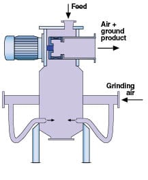
Figure 8. This fluidized-bed opposed-jet mill has an integrated deflector-wheel classifier
Grinding takes place both in the individual jets themselves and in the focal point of the jets. The gas jets introduced into the particle bed fluidize the product and draw individual particles into the jets. Fine and light particles are accelerated and blasted away at the circumference of the jet and cannot enter into the center with the highest velocity. This problem can be reduced with special multiple nozzles, which, in some cases, leads to energy savings of 30%.
The major difference between the fluidized-bed opposed-jet mill and conventional jet mills is that comminution takes place exclusively in the fluidized bed as a result of the particles impacting against each other, and is thus largely free from wear, because the particles never impact at high speed against the machine wall. The only wear-prone component in the mill is the classifying wheel, which can be protected by selection of a suitable construction material. Monobloc classifying wheels made of aluminum oxide and silicon carbide have proven themselves in operation for even the hardest and most abrasive products.
To prevent high pressure drops and increased wear, it is necessary to operate the classifying wheels at the lowest possible peripheral speeds. For large jet mills with high air flowrates, the highest fineness values can best be achieved with several small classifying wheels. This is due to the fact that at the same peripheral speed, the cut point of classifying wheels shifts into the coarse range with increasing classifying wheel diameter.
The fluidized-bed opposed-jet mill has the following strengths: finenesses down to 3 µm, depending on the product density; low degree of wear, regardless of the product hardness; low product contamination; cool grinding; easy cleaning; quiet operation; and SIP capabilities. These advantages have served to open up a wide range of applications for this mill (Table 6). The largest mills require up to 15,000 m3/h of compressed air, and the compressors needed to operate the mill are equipped with up to 1,000 kW drive power.
| Table 6: Applications for the fluidized-bed opposed jet mill | ||||
| Cool grinding | Delamination / deglomeration | Hard material | Contamination-free processing | Other |
| Toner Powder coating Wax Plant protectors Paints | Mica Talc Ceramic pigments Pigments Tungsten carbide | Abrasives Technical Ceramics Perlite Glass frits | Dental ceramics Fluorescent powders Silica gel Pharma auxiliaries Acive pharmaceutical ingredients (API) | Silica Flame retardants Rare-earth-magnet materials PTFE Graphite |
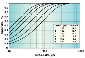
Figure 9. The particle size distributions for sugar grinding with a pin mill
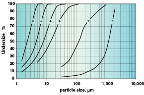
Figure 10. The particle size distributions for marble achieved in different mill types. (1) feed material; (2) impact mill with crushing disk (Figure 3a); (3) impact mill with plate beater (Figure 3b); (4) double rotor pin mill; (5) classifier mill; (6) fluidized-bed jet mill
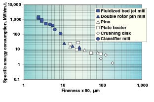
Figure 11. Specific energy consumption for grinding marble in different mill types
Pros and cons of different mills
Certain product properties can lead to a mill being particularly suitable for a specific application or to it not being suitable at all. Table 7 gives an overview of the suitability of various machine types on the basis of different criteria.
| Table 7: Suitability of different mill designs for specific applications | ||||||
| Mill design | ||||||
| Material properties | Fine impact mill | Long gap mill | Dual-rotor pin mill | Classifier mill | Spiral jet mill | Fluidized- bed jet mill |
| Fineness | > 100 µm | > 80 µm | > 32 µm | > 10 µm | > 5 µm | > 3 µm |
| Top cut | – | o | – | + | + | + |
| Mohs’ hardness < 3 | + | + | + | + | + | + |
| Mohs’ hardness > 3 | o | o | – | o | – | + |
| Heat-sensitive materials | o | o | – | o | + | + |
| Moist materials | o | + (1) | o | o | – | o |
| Sticky materials | o | o | + (2) | – | – | – |
| Machine sizes | ||||||
| Rotor diameter, mm | 50 – 1,800 | 200 – 2,800 | 50 – 1,120 | 50 – 2,000 | 30 – 1,000 (3) | 40 – 1,800 (3) |
| Drive power, kW | 0.5 – 355 | 4 – 1,400 | 2×0.5 – 2×250 | 0.5 – 500 | 1,200 (4) | |
| + ideal; o suitable to a limited degree; – not recommended | ||||||
| Footnotes: (1) The long gap mill is capable of processing products with a high moisture content — even liquid suspensions — provided that the air is preheated adequately; (2) In combination with wide-chamber design; (3) Diameter of grinding chamber; (4) Drive power of compressor | ||||||
System engineering
An impact mill on its own is not functional; it needs a more-or-less elaborate system for operation. A standard system for the classic impact mill is shown in Figure 12. Feed metering channels or screws (1) ensure a uniform feedrate. A magnet in the feed chute (2) protects the grinding elements from metallic tramp material. The door interlock (3) ensures that the mill cannot be switched on if the door is open and that the door cannot be opened if the rotor is still running. A suction-side silencer (4) reduces the noise at the site of machine installation. A large part of the ground product accumulates directly in the fines collection bin (5), whereas fine dust is collected in the automatic filter (6). A suction fan (7) compensates the filter resistance in order to maintain a slight under-pressure in the system and thus prevent formation of dust. The rotary valve at the base of the fines collection bin discharges the product and serves as an air-lock.
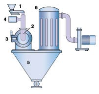
Figure 12. A standard impact mill system is composed of: a feeder (1), magnetic separator (2), a mill plus safety switch (3), a silencer (4), a product collection bin (5), an automatic filter (6) and a fan (7)
In times with the focus on customized solutions, standard systems play an increasingly insignificant role. Today, solutions are developed for the individual market segments that are more and more specific, whereby the peripheral conditions specified by a product itself must always be taken into account.
Explosion protection
Even though dust explosions are relatively rare, they can cause serious damage to people and machines when they do occur. Besides preventive measures, such as the avoidance of potentially explosive dust concentrations, the avoidance of critical oxygen concentrations by inerting and the avoidance of ignition sources, there are a number of design measures that can limit the damage in the event of a dust explosion. In laboratories, for example, inerting is often used — likewise in the pharmaceuticals industry. In the case of large systems, an explosion-pressure, shock-proof design is too expensive, and pressure venting and a reduced explosion pressure is therefore used (Figure 13). Conformance with the explosion protection directives 94/9/EC for manufacturers and 99/92/EC for owners became mandatory in the EU member countries in recent years.
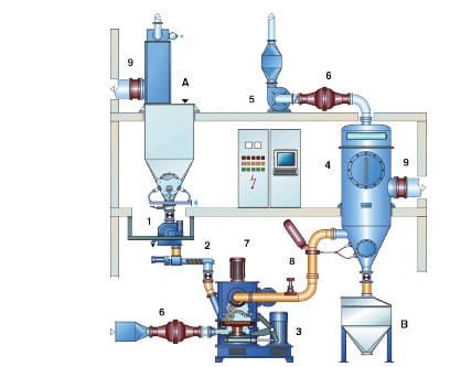
Figure 13. Flowchart of a pressure-relieved processing system with classifier mill. [(A) feed; (B) ground material; (1) metal separator; (2) feed metering screw; (3) classifier mill; (4) reverse jet filter; (5) fan; (6) explosion-barrier valve (7) explosion venting; (8) fire extinguishing system; (9) rupture disk]
Compact system
In the case of brittle products that have a low grinding energy, there is a high mass flowrate of product through the grinding system. Thus, the system can be cooled by the product and does not need additional cooling by an air flow through the system. A compact system without dust collector can be designed for these applications. This is especially advantageous for potentially dust-explosive products, because the system is so compact that it can easily be built in a 10 barg design to withstand dust explosions (Figure 14). This ensures a safe operation of the system and saves investment costs. An example for the use of such compact systems is milling sugar, which is preferably ground with pin discs (see also Figure 9).
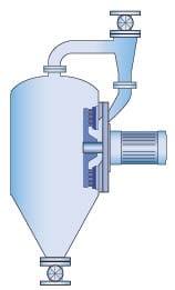
Figure 14. Shown here is a compact grinding system with pin mill and two air-locks
Cryogenic grinding
Some materials that are subject to plastic deformation at ambient temperature can be cooled to make them brittle enough to be subsequently ground by impact. Cryogenic grinding is used for spices to make sure that the flavor and aroma is preserved. At the same time, cryogenic grinding also increases the throughput. Other applications are the fine grinding of plastics and rubber. The supply of nitrogen is controlled as a function of the mill outlet temperature. The temperatures downstream of the mill often range between 0 and –20°C. The nitrogen requirement is considerable and usually ranges between 1 and 3 kg of liquid N2 per kilogram of product, which naturally raises the costs significantly.
Figure 15 shows a cryogenic grinding system operated with liquid nitrogen. Large sections of the system are insulated to reduce the nitrogen requirement, and the cold air is circulated. Operating in the through-air mode is out of the question because freezing water from the air would cause the mill to ice up.
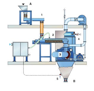
Figure 15. Cryogenic grinding system operated with liquid nitrogen [(A) feed; (B) ground material; (1) feed metering channel; (2) screw cooler supplied with liquid nitrogen (LN2); (3) dual-rotor pin mill; (4) automatic filter; (5) temperature sensor]
Pharma systems
The demands posed by the pharmaceutical industry are very different, depending on whether active substances or additives are to be processed and in what form the medicine will be administered. In the case of highly active substances, the batches are relatively small, and thus so are the machines and systems used to process these products. Another important point is that the production personnel must be afforded effective protection. This has led to the increasing use of isolators (Figure 16). A machine is much more difficult to operate if housed in an isolator, than under normal conditions. Grinding systems in isolators are unique systems with every detail designed to users’ needs.
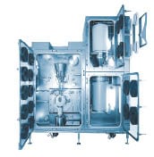
Figure 16. This fine impact mill inside an isolator features a mill housing and grinding elements in monobloc design, and polished surfaces (Ra = 0.8 µm)
Final remarks
During the last decades impact grinding has gone through several developments. Dust emissions of systems have been reduced. Products have become finer and finer. Processes have become more stable by using classifiers. Machines have become more reliable in continuous operation. Nowadays customized solutions are available for many applications. Future developments will be: machine diagnosis for planned preventative maintenance, noise reduction, energy efficient grinding processes and use of wear-resistant construction materials to process harder products by impact grinding. ♦
Edited by Gerald Ondrey
Author

Bodo Furchner is general manager of the technical division of Hosokawa Alpine AG (Peter-Dörfler-Str. 13-25, D-86100 Augsburg, Germany; Phone: +49-821-5906-0; Fax: +49-821-5906-234; Email: [email protected]), a position he has held since 1993. Prior to this, he was manager of Hosokawa Alpine’s Test Center Mechanical Processing from 1995–1999, and worked in the companys R&D department since 1987. Furchner earned a process-engineering degree from the Technical University of Munich, as well as a Ph.D., which he earned while working as scientist at the Institute for Process Engineering in the team of Professor Mersmann.