An understanding of instrumentation is valuable in evaluating and troubleshooting column performance
Instrumentation is critical to understanding and troubleshooting all processes. Very few engineers specialize in this field, and many learn about instrumentation through experience, myth and rumor. A good understanding of the various types of instrumentation used on columns is a valuable tool for engineers when evaluating column performance, starting up new towers or troubleshooting any type of problem. This article gives an overview of the common types of instruments used for pressure, differential pressure, level, temperature and flow. A discussion of their accuracy, common installation problems and troubleshooting examples are also included.
The purpose of this article is to provide some basic information regarding the common types of instrumentation found on distillation towers so that process engineers and designers can do their jobs more effectively.
Anyone trying to complete a simple mass balance around a column understands that process data contain some error. Closing a mass balance within 10% using plant data is usually considered very good. Generally, some values must be thrown out when matching a model to plant data. Understanding which measured plant data is likely to be most accurate is invaluable in making good decisions about a model of the plant, column performance and future designs.
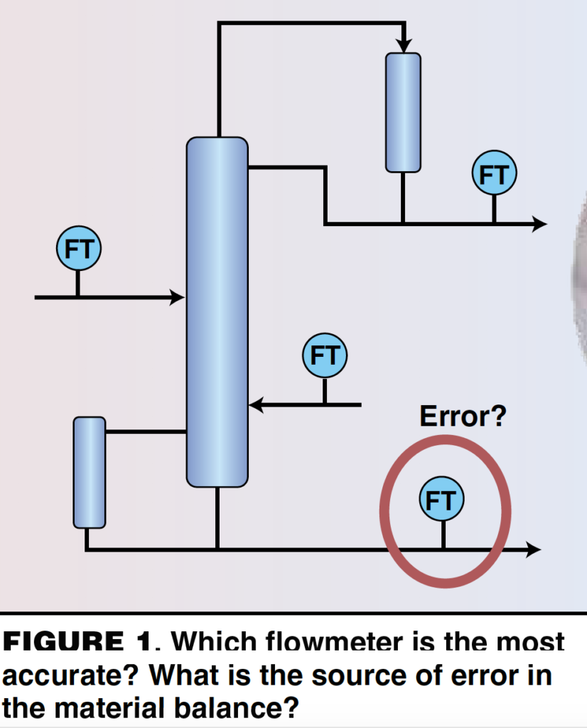
The following is a real case and a telling example of how little the average chemical engineer may understand about instrumentation. A process engineer with over 20 years of experience was doing a material balance around a distillation tower, illustrated in Figure 1. Based on the material balance, the engineer concluded that the bottoms flowrate must be in error and wrote a work order to have the flowmeter recalibrated. The instrument group disagreed heartily. By the end of this article, the reader will understand the instrument group’s response.
Pressure
There are three common types of pressure transmitters: flush-mounted diaphragm transmitters, remote-seal diaphragm transmitters and impulse-line transmitters. All use a flexible disk, or diaphragm, as the measuring element. The deflection of the flexible disk is measured to infer pressure. The diaphragm can be made of many different materials of construction, but the disk is thin and there is little tolerance for corrosion. Coating of the diaphragm leads to error in the measurement. The instrument accuracy of all three types of pressure transmitters is similar, usually 0.1% of the span, or calibrated range.
Flush-mounted diaphragms
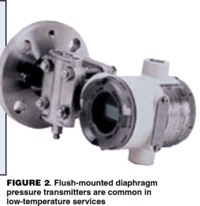
These pressure transmitters are common in low-temperature services, such as in scrubbers and storage tanks. The process diaphragm, an integral part of the transmitter, is mounted on a nozzle directly on the vessel, and the transmitter is mounted directly on the nozzle. See Figure 2.
Remote-seal diaphragm
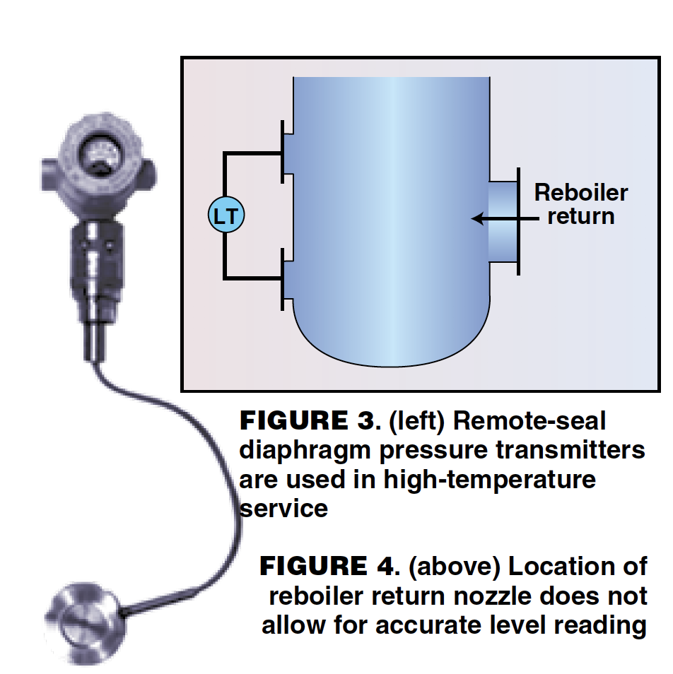
Used in higher temperature service when the electronics must be mounted away from the process, a flush-mounted diaphragm is installed on a nozzle at the process vessel. A capillary tube filled with hydraulic fluid connects the flush-mounted diaphragm to a second diaphragm, which is located at the remotely mounted pressure transmitter. The hydraulic fluid must be appropriate for the process temperature and pressure. Hydraulic fluid leaks will lead to errors in measurement. Calibration is complex because the head from the hydraulic fluid must be considered. The calibration changes if the transmitter is moved, the relative position of the diaphragms changes or if the hydraulic fluid is changed.
Impulse-line
Impulse-line pressure transmitters can either be purged or non-purged. Purged impulse-line pressure transmitters measure purge-fluid pressure to infer the process pressure. Most commonly, the purge fluid is nitrogen, but it can also be air or other clean fluids. The purge fluid is added to an impulse line of tubing to detect pressure at the desired point in the process. The purge fluid enters the process and must be compatible with it. Check valves are required to ensure that process material does not back up into the purge-fluid header. The system must be designed so that the pressure drop through the impulse line is negligible. A pressure transmitter measures the purge-fluid pressure with a diaphragm to infer the process pressure.
Non-purged, impulse-line
Rather than a purge fluid, this type of pressure transmitter uses process fluid. Usually, this style is chosen when the process is non-fouling or it is undesirable to add inerts to the process. One example is a situation where emissions from an overhead condenser vent must be minimized. An impulse line is connected from the desired measurement point in the process to a pressure transmitter, which measures the process pressure at the remote point. The system must be designed so that the pressure drop through the impulse line is negligible. The system designer must consider the safety implications of an impulse-line failure. The consequence of releasing hazardous material from a tubing failure may warrant the selection of a different type of pressure transmitter. Adequate freeze protection on the impulse lines is also important to obtain accurate measurements.
Example 1. A good example of a problem with impulse-line pressure transmitters can be found in Kister’s Distillation Troubleshooting [ 2]. Case Study 25.3 (p. 354), contributed by Dave Simpson of Koch-Glitsch U.K., describes three redundant impulse-line pressure transmitters used to measure column head pressure. Following a tray retrofit, operating difficulties eventually led to suspicion of the head pressure readings. The impulse lines and pressure transmitters had been moved during the turnaround. The transmitters had been moved below the pressure taps on the vessel. Condensate filled the impulse lines and caused a false high reading. Relocating the transmitters to the original location above the nozzles solved the problem by allowing condensate to drain back into the tower.
Transmitters in vacuum service
Pressure transmitters in vacuum service are generally the most problematic, leading to greater inaccuracy in the measured value. Damage to the diaphragm can occur from exceeding the maximum pressure rating of the instrument. Often, this happens on startup, or it can happen when performing a pressure test of the vessel. The diaphragm deflects permanently and introduces error.
Calibration of vacuum pressure transmitters is more difficult for instrument mechanics. The operating range must be clearly defined; for example, is the range 100-mm Hg vacuum, 100-mm Hg absolute, or 650-mm Hg absolute? Using different measurement scales in the same plant is confusing, and it can make it very hard for mechanics to calibrate the pressure transmitters accurately.
Another issue is measuring the relief pressure. The system designer must consider the instrument ranges available and the accuracy of the measurement for the operating range versus the relief pressure range. It is good practice to install a second pressure transmitter on vacuum towers to measure the relief pressure.
Example 2. An excellent example of calibration problems is illustrated in vacuum service in Reference [2]. Case Study 25.1 (p. 348), contributed by Dr. G. X. Chen of Fractionation Research, Inc., describes several years of troubleshooting a steam-jet system in an attempt to achieve 16-mm Hg absolute head pressure on a tower. It was eventually determined that the calibration of the top pressure transmitter was wrong, and they had been pulling deeper vacuum than they thought. The top pressure transmitter was calibrated using the local airport barometric pressure, which was normalized to sea-level pressure and was off by 28-mm Hg.
Differential pressure
Differential pressure can be measured either with a differential pressure (dP) meter or by subtracting two pressure measurements. Subtracting two pressure readings is not always accurate enough to obtain a meaningful measurement, so it is important to consider the span of the anticipated measured readings. If the dP is a substantial fraction of the top pressure, then it is okay to subtract the readings of two pressure transmitters. However, if the dP is a small fraction of the top pressure, then it will be within the instrument error of the pressure transmitter.
For example, a column at a plant runs at 30 psia top pressure. The expected dP is 2-in. H 2 O over a few trays. The instrument error for a 0 – 50 psi pressure transmitter is 1.4-in. H 2 O. The measurement is within the accuracy of the pressure transmitters, and a dP meter is the appropriate meter to obtain an accurate measurement. The downside of dP meters is that very long impulse lines are required on tall towers.
Level
Level and flow are the hardest basic things to measure on a distillation tower. Kister reports that tower base level and reboiler return problems rank second in the top ten tower malfunctions, citing that “Half of the case studies reported were liquid levels rising above the reboiler return inlet or the bottom gas feed. Faulty level measurement or control tops the causes of these high levels…Results in tower flooding, instability, and poor separation…Vapor slugging through the liquid also caused tray or packing uplift and damage.” (Reference 2, p. 145)
One of the main reasons for faulty level indications is that dP meters are the most common type of level instrument, and an accurate density is required to convert the dP reading to a level reading. In many cases, froth in the liquid level decreases the actual density and causes faulty readings. Changes in composition or the introduction of a different process feed with a different density are cited several times as reasons for level measurement problems. Plugging of impulse lines and equipment arrangements that make accurate readings impossible are also very common problems.
Differential pressure transmitters are the most common type of level transmitter. The accuracy of the instrument is quite good, at 0.1% of span (calibrated range). Any type of dP meter can be used: flush-mounted diaphragms, remote-seal diaphragms, purged impulse-line, or non-purged impulse-line pressure transmitters. The level measurement is dependent on the density of the fluid:

An accurate density is required for calibration. Changes in composition or the introduction of a process feed with a different density will cause erroneous readings. Level transmitters suffer from the same problems that occur in pressure transmitters. Hydraulic fluid leaks, compatibility of the hydraulic fluid, damage to diaphragms, and plugging or freezing of impulse lines are just a few of the problems that can be encountered with dP level transmitters.
Example 1. A column in a high-temperature, fouling service began to experience high pressure drop, and the plant engineers were concerned that they were flooding the column. Calculations showed that the tower should not be flooding if the trays were not damaged. Downcomer flooding was a possibility if the cartridge trays had become dislodged and reduced the downcomer clearance. The tower was taken down, and internal inspection revealed no damage to the internals. It was determined that a false low level caused the bottoms flow controller to close. This raised the level in the tower above the reboiler return line and above the lower column pressure tap. The column dP meter was reading the height of liquid above the lower-column pressure tap. Consultation with the instrument manufacturer revealed that the remote, seal hydraulic fluid was not appropriate for the high temperature of the process. The hydraulic fluid was boiling in the capillary tubes and had deformed the diaphragm, which was also coated from the fouling service. The level transmitter was switched to a periodic, purged impulse-line dP meter. An automated high-flow nitrogen purge prevents accumulation of the solids in the impulse lines and is done once per shift. Logic was added to the control loop to maintain the previous level reading during the short nitrogen purge, a method that has eliminated the problem with the level.
Example 2. Another common example of a level transmitter failure is based on the fact that equipment is designed in such a way that an accurate level reading can never be obtained. Though this may be surprising, it is mentioned in Ref. [ 3], Case Study 8.4 (p. 149), as illustrated in Figures 3 and 4. A column that was being retrofitted was originally designed so that the reboiler return was introduced directly between the two liquid-level taps. The level in the tower could never be accurately measured, and it was modified on the retrofit to rectify this situation.
Nuclear level transmitters
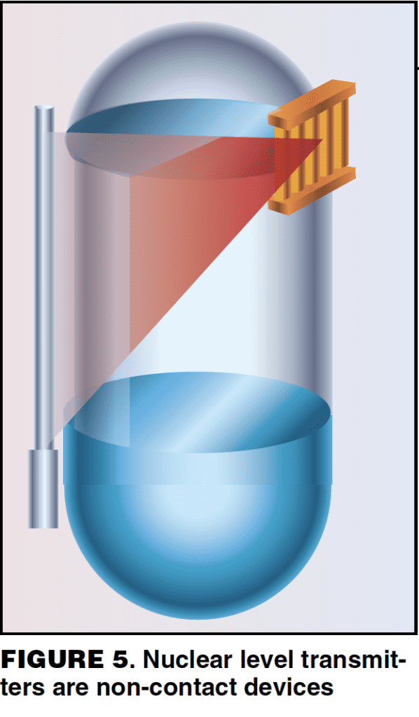
Common in polymer, slurry and highly corrosive or fouling services, these instruments work by placing a radioactive source on one side of the vessel and a detector on the other side. The amount of radiation reaching the detector depends on how much material is inside the vessel. A strip source and strip detector are more accurate than a single source, strip detector. A sketch of a single source, strip detector is shown in Figure 5. The advantage of nuclear level transmitters is that they are non-contact devices, making them ideal for services where the process fluid would coat or damage other types of level instruments.
Nuclear level transmitters are more expensive than other level devices. They also require permits and a radiation safety officer, so they are often only used as a last resort. The instrument accuracy is generally ±1% of span. The total accuracy depends on how well the system was understood by the designer and installer. The thickness of the vessel walls and any other metal protrusions in the measuring range, such as baffles, must be taken into account in the calibration, along with the correct rate of decay of the source. Build-up of solids in the measuring range will also result in error.
Radar level transmitters
This type of level transmitter has been used in the chemical processing industries (CPI) for the last 30 years. They demonstrate high accuracy on oil tankers and have been used frequently in storage-tank applications. Radar level transmitters are now being applied to distillation towers but are still more commonly found on auxiliary equipment, like reflux tanks. There are contact and non-contact types of radar level instruments.
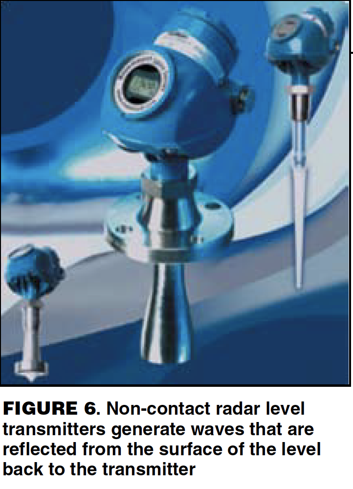
A non-contact, radar level transmitter (Figure 6) generates an electromagnetic wave from above the level being measured. The wave hits the surface of the level and is partially reflected to the instrument. The distance to the surface is calculated by measuring the time of flight, which is the time it takes for the reflected signal to reach the transmitter. Some things that cause inaccuracy with non-contact radar are: size of the cone, heaving foaming, turbulence, deposits on the antenna, and varying dielectric constants caused by changes in composition or service. The instrument accuracy is reported as ±5 mm.
Contact radar sends an electromagnetic pulse down a wire to the vapor-liquid interface. A sudden change in the dielectric constant between the vapor and the liquid causes some of the signal to be reflected to the transmitter. The time of flight of the reflected signal determines the level.
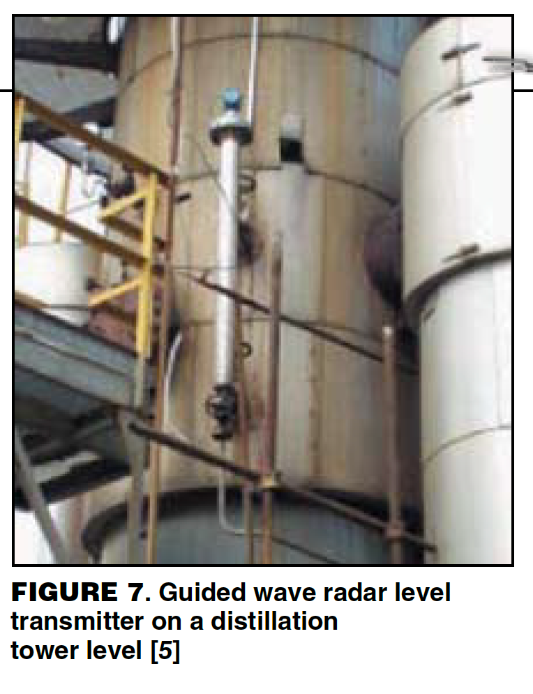
Guided wave radar can be used for services where the dielectric constant changes, but is not a good fit for fouling services. A bridle (Figure 7), is used on distillation towers to reduce turbulence and foaming and therefore increases the accuracy of the measurement. Instrument accuracy is ±0.1% of span.
Example 3. A reflux tank on a batch distillation tower had a non-contact radar level transmitter. The tower stepped through a series of water washes, solvent washes, and process cuts. The reflux-tank level transmitter gave false high readings during the solvent wash cycle, which used toluene. The reflux pumps would always gas off during this part of the process. The dielectric constants of the various fluids in the reflux tank, of which toluene had the lowest dielectric constant, varied ten times during the cycle, affecting the height of liquid able to be measured. Larger antennas focus the signal more and give greater signal strength. As the dielectric constant decreases, a larger antenna is required to measure the same height of fluid. The level transmitter used in this service was not appropriate for all measured fluids and could not accurately measure the liquid level when the reflux drum was inventoried with toluene.
Temperature
There are two common types of temperature transmitters in distillation service — thermocouples and Resistive Temperature Devices (RTDs). Both are installed in thermowells.
Thermocouples. The most popular temperature transmitter, thermocouples, consist of two wires of dissimilar metals connected at one end. An electric potential is generated when there is a temperature delta between the joined end and the reference junction. Type J thermocouples, made of iron and Constantine, are commonly used in the CPI for measuring temperatures under 1,000°C.
RTDs
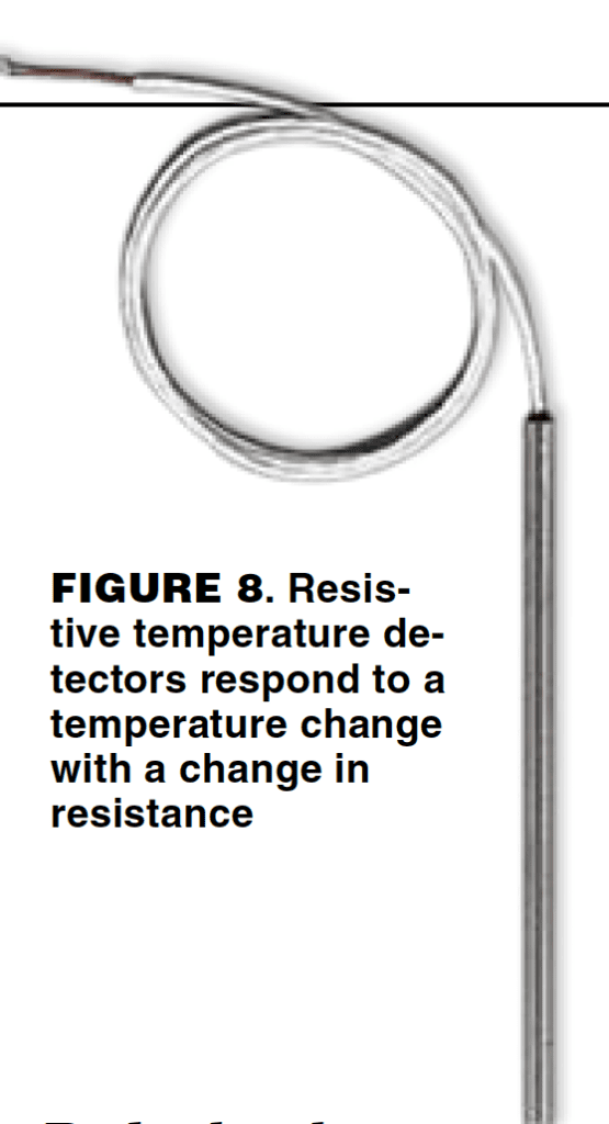
The second most-common type of temperature transmitter, RTDs consist of a metal wire or fiber that responds to a temperature change by changing its resistance (Figure 8). Though RTDs are less rugged than thermocouples, they are also more accurate. Typically, they are made of platinum. The instrument accuracy of thermcouples and RTDs is very good in both. However, thermocouples have a higher error than RTDs. The total accuracy of a thermocouple is 1 – 2°C. There is greater error due to calibration errors and cold-reference junction error.
It is important to note that, with temperature transmitters, there is a lag in the dynamic response to changes in process temperatures. All temperature measurements have a slow response, because the mass of the thermowell must change in temperature before the thermocouple or RTD can see the change. The lag time will depend on the thickness of the thermowell and on the installation. The thermocouple and RTD must be touching the tip of the thermowell for best performance. If there is an air gap between the thermowell and the measuring device, the heat-transfer resistance of the air will add substantially to the lag time, which is also why temperature transmitters work better in liquid service. The response time for temperature transmitters in liquid service is between 1 – 10 s, whereas the response time for temperature transmitters in vapor service is about 30 s. Heat-transfer paste is a thermally conductive silicone grease; it has been used with success in some plants to improve the response time of temperature transmitters.
Example. The plant in this example experienced a temperature lag problem. A thermocouple near the bottom of a large tower controlled the steam to the reboiler. The temperature control point had a 10-min delayed response to changes in steam flowrate. The rest of the column responded to the change in boilup in about 3 min. The lag in the control point caused cycling of the steam flowrate and created an unstable control loop. The cause was determined to be a thermocouple that was too short for its thermowell. Normally, thermocouples are spring-loaded to ensure that the tip is touching the end of the thermowell, but the instrument mechanics had installed a thermocouple of the wrong length because they lacked the proper replacement part. The poor heat transfer through the air gap between the end of the thermocouple and the thermowell caused the delay in temperature response. Replacing the installed thermocouple with one of the proper length fixed the problem.
Flow
There are many different types of flowmeters. Here, the types commonly used in plants will be discussed: orifice plates, vortex shedding meters, magnetic flowmeters and mass flowmeters.
Orifice plates
Orifice plates are the most common type of industrial flowmeter. They are inexpensive, but they also have the greatest error of all the common types of flowmeters. Orifice plates measure volumetric flowrate according to the following equation:
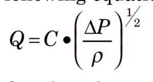
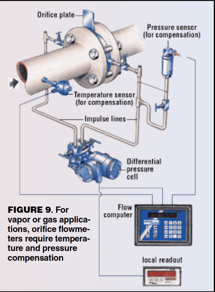
Q is the volumetric flowrate, C is a constant, ΔP is the pressure drop across the orifice, and ρ is the fluid density. To obtain an accurate flowrate, an accurate fluid density must be known. Temperature and pressure compensation are required for vapor or gas applications and may be required for some liquids. Figure 9 shows the equipment arrangement for an orifice flowmeter with temperature and pressure compensation.
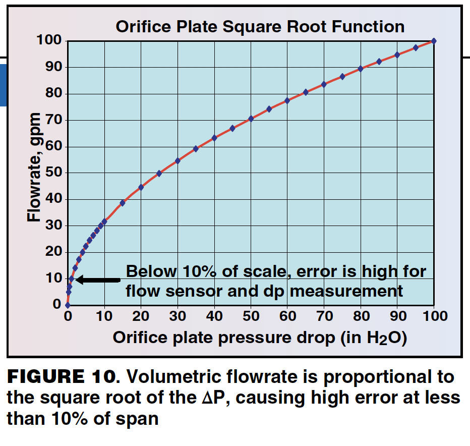
Typical turndown for orifice plates is 10:1. Below 10% of span, the measurement is extremely erroneous because the volumetric flowrate is proportional to the square root of the ΔP. At 10% of span, the meter is only measuring 1% of the ΔP span (Figure 10).
Multiple meters can be used to overcome the turndown ratio when high accuracy is required over the entire span. This is often worth the effort when measuring the flowrate of raw materials or final products. At one plant, three orifice plates in parallel were used to measure the plant-boundary steam flowrate due to the large span and the accuracy required at the low end of the range. This resulted in a very complicated system.
There are many common problems that lead to error in the orifice plate measurement, including inaccurate density, impulse-line problems, erosion of the orifice plate, and an inadequate number of pipe diameters upstream and downstream of the orifice plate.
An accurate density is required to obtain an accurate flowrate. In a plant that has a process feed that varies from as low as 12% to as high as 30% water, the density changes significantly, and therefore an orifice meter will not provide an accurate reading without density compensation.
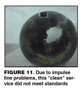
Impulse line problems include plugging, freezing due to loss of electric heat tracing, and leaking. Condensate filling the impulse lines in vapor/gas service and gas bubbles in the impulse lines in liquid service are also commonly cited. Figure 11 shows a pipe just upstream of an orifice that was in “clean” water service for two years. There was a filter just upstream of this section of pipe. The impulse lines to the orifice plate flowmeter were completely plugged. This section of pipe was removed and a Teflon-lined magnetic flowmeter was installed instead.
Orifice plates can erode, especially in vapor service with some entrained liquid. This is common in steam service, and orifice plates should be checked every three years for wear.
Orifice plates generally need 20 pipe diameters upstream and 10 pipe diameters downstream of the orifice plate for the velocity profile to fully develop for predictable pressure-drop measurement. This requirement varies with the orifice type and the piping arrangement. This is rarely achieved in a plant, which introduces error in the measurement.
The instrument accuracy of orifice plates ranges from ±0.75 – 2% of the measured volumetric flowrate. Various problems are encountered with orifice plate installations, and they have the highest error of all flowmeters. “Orifice plates are, however, quite sensitive to a variety of error-inducing conditions. Precision in the bore calculations, the quality of the installation, and the condition of the plate itself determine total performance. Installation factors include tap location and condition, condition of the process pipe, adequacy of straight pipe runs, gasket interference, misalignment of pipe and orifice bores, and lead line design. Other adverse conditions include the dulling of the sharp edge or nicks caused by corrosion or erosion, warpage of the plate due to water hammer and dirt, and grease or secondary phase deposits on either orifice surface. Any of the above conditions can change the orifice discharge coefficient by as much as 10%. In combination, these problems can be even more worrisome and the net effect unpredictable. Therefore, under average operating conditions, a typical orifice installation can be expected to have an overall inaccuracy in the range of 2 to 5% AR (actual reading)” [ 6].
Vortex shedding meters
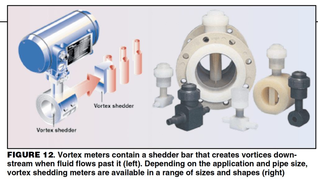
Vortex shedding meters contain a bluff body, or a shedder bar, that creates vortices downstream of the object when a fluid flows past it (Figure 12). The meters utilize the principle that the frequency of vortex generation is proportional to the velocity of the fluid. The whistling sound that wind makes blowing through tree branches demonstrates the same phenomenon.
The fluid’s density and viscosity are used to set a “k” factor, which is used to calculate the fluid velocity from the frequency measurement. The frequency, or vibration, sensor can either be internal or external to the shedder bar. The velocity of the fluid is converted to a mass flowrate using the fluid density. Therefore, accurate fluid density is important for accurate measurements. Vortex meters work well both in liquid and gas service. They are commonly used in steam service because they can handle high temperatures. They are available in many different materials of construction and can be used in corrosive service.
Vortex meters have lower pressure drop and higher accuracy than orifice plates. A minimum Reynolds number (Re min) is required to achieve the manufacturer’s stated accuracy. Vortex meters exhibit non-linear operation as they transition from turbulent to laminar flow. Typical accuracy above the Re min is 0.65 – 1.5% of the actual reading. In general, the meter size must be smaller than the piping size to stay above the Re min throughout the desired span. The requirements for straight runs of pipe upstream and downstream of the meter vary, but both are usually longer than for orifice plates. In general, 30 pipe diameters are required upstream and 15 pipe diameters downstream. The upstream and downstream piping must be the same size pipe as the meter.
There are only a few problems commonly encountered with vortex meters. Older models may be sensitive to building vibrations, but newer models have overcome this issue. If the shedder bar becomes coated or fouled, the internal vibration sensor will cease to work. This can be avoided by using an external vibration sensor. The most common issue is failing to meet the Re min requirements over the desired span. At one plant, every vortex meter was line-sized, which means it was the same size as the surrounding piping. The flow went into the laminar region in the desired measured range in every case. The flow read zero when it transitions to laminar, making the meters useless.
Example. Another good example of failing to meet the Re min requirements over the desired span happened on a project where a tower that had been out of service for some time was recommissioned. The distillate flowrate was substantially lower than the original tower design and was in the laminar flow region over the entire operating range. The distillate flow was a major control point on the tower, but the vortex meter could not read the flowrate. The control strategy had to be changed to work around this issue until an appropriate meter could be installed.
Magnetic flowmeters
Faraday’s law states that the voltage induced across any conductor as it moves at right angles through a magnetic field is proportional to the velocity of that conductor. This is the principle used to measure velocity in magnetic flowmeters, which are commonly referenced to as mag meters (Figure 13).
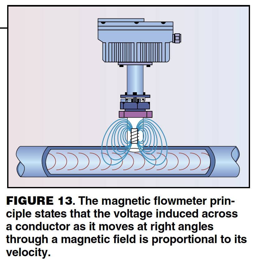
Mag flowmeters measure the volumetric flowrate of conductive liquids. Fluids like pure organics or deionized water do not have a high enough conductivity for a mag meter. An accurate density is required to convert the volumetric flowrate to a mass flowrate. The meters are line-sized, but they have a minimum and maximum velocity to achieve the stated instrument accuracy. A smaller line size may be necessary to achieve the velocity requirements throughout the desired span. The instrument accuracy is quite good, generally at ±0.5% of the actual reading. The error is very high below the minimum velocity. Turndown for newer mag meters is 30:1, but older models will be closer to 10:1.
Mag meters do not have a lot of operating problems. They must be liquid-full to get an accurate reading and are often placed in vertical piping to achieve this. They rarely plug as they can be specified with Teflon liners and are often used in slurry service. Mag flowmeters are more expensive to install because they usually require 110-V power.
Mass flowmeters
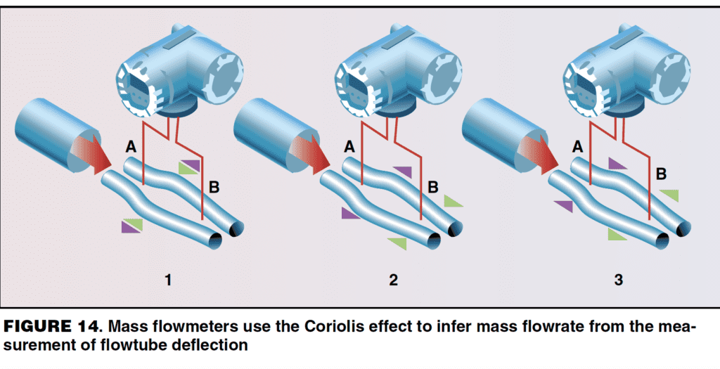
Mass flowmeters use the Coriolis effect to measure mass flowrate and density. A very small oscillating force is applied to the meter’s flowtube, perpendicular to the direction of the flowing fluid. The oscillations cause Coriolis forces in the fluid, which deform or twist the flowtube. Sensors at the inlet and outlet of the flowtube measure the change in the geometry of the flowtube, which is used to calculate the mass flowrate. The oscillation frequency is used to measure the fluid’s density. The temperature of the fluid is measured to compensate for thermal influences and can be chosen as an output of the meter.
The original mass meters were U-tubes, but several different shapes are now available, including straight tubes as shown in Figure 14. Mass flowmeters have the highest accuracy of all the different types of flowmeters, usually ±0.1 – 0.4% of the actual reading. The measurement is independent of the fluid’s physical properties, making mass flowmeters unique in that most flowmeters require the fluid density as an input. Mass flowmeters are insensitive to upstream and downstream pipe configurations. Practical turndown is 100:1, although the manufacturers claim 1,000:1. The density measurement is not as accurate as a density meter. Mass flowmeters are generally very reliable and only require periodic calibration to zero them.
Mass flowmeters are on the expensive end to purchase and to install. They require 110-V power. Pressure drop can sometimes be an issue, and the meters are only available in line sizes up to 6 in. Coating of the inside of the flowtube will result in higher pressure drop and can result in loss of range and accuracy if the tube is restricted. Wear and corrosion can result in a gradual change of the mechanical characteristics of the tube, resulting in error. Zero stability was an issue with older meters but this problem has been solved in newer units.
Example 1. The reflux flowrate on a final product column was an important measurement, and the reliability of the existing flowmeter was questioned. Product literature for mass flowmeters promised high accuracy and low pressure drop. The plant-area engineer coordinated a small project to replace the existing orifice plate flowmeter with a mass flowmeter. Column performance was very poor after startup. The new meter had to be bypassed to operate the column normally. The overhead condenser was gravity drained, and the new mass flowmeter had enough additional pressure drop to force the liquid level into the condenser tubes and restrict rates — an expensive lesson for a new engineer.
Example 2. Another tower had a mass flowmeter installed on the bottoms flow, which was pumped but not cooled. The mass flowmeter always had erratic readings and was never believed. A closer examination of the system revealed enough pressure drop through the mass flowmeter to result in flashing in the flowtube. The two-phase flow caused the erratic readings.
With a knowledge of the basics of column instrumentation, the question posed in the introduction should seem trivial. Our experienced engineer had concluded that the bottoms flowrate of the column had to be erroneous, but the instrument group had disagreed. The flowmeter in question was a mass flowmeter in relatively clean and non-corrosive service. The other three flowmeters on the column were orifice plates and are known to have a myriad of problems that introduce error.
Some basic knowledge of instrumentation can be a very valuable troubleshooting and design tool. Gauging whether an instrument installation will ever give accurate readings or whether it is an expensive spool piece is useful in itself. Being able to assess the relative accuracy of two measurements will help determine from which data to draw conclusions. Knowledge of common instrument problems can help in troubleshooting.
Get to know the instrumentation on your towers. Gather the manufacturer’s information so you can assess the instrument accuracy. Keep in mind that the manufacturer’s literature refers to the ideal instrument accuracy, which is the accuracy of the measuring device itself. There are many other factors that contribute to the accuracy of the reading that is displayed on the DCS screen or in the data historian. The total accuracy includes the instrument accuracy plus all of the other things that contribute to error in the measured reading as compared to the actual value. Other inaccuracies lie in digital to analog conversions, density errors, piping configurations, calibration errors, vibration errors, and the list goes on and on. Check the field installation to see what types of problems your meters will experience.
Get to know your mechanics and instrumentation experts at your plant. Now that you know some of the lingo of instrumentation, you can better converse with your instrument engineers and mechanics.
Acknowledgements
This paper is a compilation of instrumentation basics obtained from the references listed below, of troubleshooting experience from many colleagues at DuPont, and of troubleshooting examples from Henry Kister’s most recent book, Distillation Troubleshooting. Much of the technical information and many of the examples come from Nick Sands, Process Control Leader for DuPont Chemical Solutions Enterprise in Deepwater, N.J. Nick has worked for DuPont for 17 years and is a specialist in process control. In addition to Nick, the following DuPont colleagues contributed their instrument war stories, and the author is grateful for their willingness to share their experiences:
-
Jim England, DuPont Electronic Technologies (Circleville, Ohio)
-
Charles Orrock, DuPont Advanced Fibers Systems (Richmond, Va.)
-
Adrienne Ashley, DuPont Advanced Fibers Systems (Richmond, Va.)
-
Joe Flowers, DuPont Engineering Research & Technology (Wilmington, Del.)
DefinitionsInstrumentation range The instrumentation range, the scale over which the instrument is capable of measuring, is built into the device by the manufacturer. The purchaser defines the desired measured range, and the vendor should provide a device that is appropriate for the application. Calibrated range The calibrated range is the scale over which the instrument is set to measure at the plant. It is a subset of the instrument range. The calibration has a zero and a span. The zero is the minimum reading, while the span is the width of the calibrated range. The calibrated range will simply be referred to as the range at a plant site. Instrument accuracy Accuracy = (Error/Scale of Measurement) x 100% The instrument accuracy is published by the manufacturer in the product documentation, which is easily obtained on-line. A few examples of how accuracy can be expressed are:
These examples refer to the ideal instrument accuracy, which is only the accuracy of the measuring device itself. The total accuracy, on the other hand, includes the instrument accuracy plus all other factors that contribute to error in the measured reading as compared to the actual value. These other factors can include digital to analog conversions, density errors, piping configurations, calibration errors, vibration errors, plugging and more. Turndown ratio Turndown ratio = maximum accurate value/minimum accurate value The ratio of the maximum to minimum accurate value is an important factor in considering the total accuracy of a measured value. For example, an instrument with 100:1 turndown and 0 – 100- psi instrument range would have the stated instrument accuracy down to 1 psi. Below 1 psi, the instrument might read, but it will have greater inaccuracy. |
References
|
AuthorRuth Sands is a senior consulting engineer for DuPont Engineering Research & Technology (Heat, Mass & Momentum Transfer Group, 1007 Market St., B8218, Wilmington, DE 19898; Phone: 302-774-0016; Fax: 302-774-2457; Email: [email protected]). She has specialized for the last nine years in mass transfer unit operations: distillation, extraction, absorption, adsorption, and ion exchange. Her activities include new designs and retrofits, pilot plant testing, evaluation of flowsheet alternatives, and troubleshooting. She has 17 years of experience with DuPont, which includes assignments in process engineering, manufacturing, and corporate recruiting. She holds a B.S.Ch.E. from West Virginia University, is a registered professional engineer in the state of Delaware, and is a member of the FRI Executive Committee. |