When transferring stored bulk-solids materials from hoppers, bins and silos, flow stoppage can occur because of bridging or arching at the vessel outlet. Hopper outlets must be large enough to prevent cohesive arches or stable ratholes from developing. Determining the size and shape of the hopper outlet is critical to ensuring that the bulk material flows. This column provides information on the interplay between bulk material properties and vessel geometry and how those relate to outlet size and shape.
Arch and rathole formation
Bulk solids can experience a range of conditions within a bin, silo or storage hopper. Consolidation pressures range from zero at the surface, to relatively large values at increasing depth within the container. If a solid gains cohesive strength because of the pressures applied to it, an arch or rathole could form. An arch (also called a bridge or dome) is a stable obstruction that forms over the point of narrowest cross-section of the storage vessel (usually the discharge outlet). The arch supports the rest of the bin contents, preventing discharge (Figure 1, left). A rathole is a stable pipe or vertical cavity that empties out over the outlet. Material is left stranded in stagnant zones that usually remain in place until an external force is applied to dislodge them.
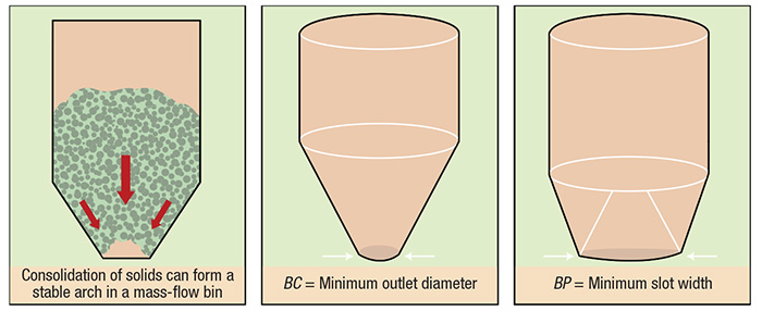
Figure 1. The size of the discharge outlet is a critical element in preventing the formation of an arch in a mass-flow bin
Flow functions
Cohesive strength can be measured as a function of the applied consolidation pressure. By conducting the test over a range of consolidation states, the relationship between consolidation pressure and the cohesive strength of the bulk material can be established, following a procedure established and described by Jenike [1]. In a laboratory, a sample of the material is placed in a direct shear tester and both compressive and shear loads are applied to simulate flow conditions in a container. Once the sample has been consolidated, its strength is measured by shearing it to failure. By repeating this procedure under different conditions, the resulting value of strength versus consolidating pressure (called a flow function) can be developed. The material’s flow function is then used to calculate minimum outlet dimensions.
Once a material’s flow function has been determined, the minimum outlet width or diameter that will prevent cohesive arching can be calculated using the hopper’s flow factor. The flow factor is a function of the powder’s effective angle of internal friction, the hopper angle and the wall friction angle. Typical values of the flow factor range between 1.1 and 1.7. For more on calculating flow functions and flow factors, see Refs. 2 and 3.
Mass- versus funnel-flow bins
Two types of bin flow patterns are possible. A mass-flow bin has a relatively long, tapered discharge section. In mass flow, all of the material is in motion during discharge, so no stagnant regions form. Conversely, a funnel-flow bin has a relatively short converging section. While storage capacity for a given height is greater in a funnel-flow bin, this geometry allows material in the center to move, while material at the walls is stationary. The resultant stagnant regions may interrupt flow.
Compared with a mass-flow bin, there are several potential advantages to using a funnel-flow bin. The relatively shallow hopper requires less headroom for a given storage capacity, and since there is minimal flow along the walls, the likelihood of abrasion and particle attrition is minimized. However, In general, only free-flowing solid materials with large (≥1/4 in.) particle sizes and minimal tendency to degrade (via oxidation, caking and so on) will flow reliably in funnel-flow bins.
Preventing arching
For a mass-flow bin with a circular outlet, the minimum outlet diameter needed to prevent arching is expressed as BC (Figure 1, center). Consider a material whose critical outlet dimension, BC, is 12 in. If this material is placed in a mass-flow bin with an outlet diameter of 6 or 8 in., a stable arch will form. Conversely, if the outlet size is 12 or 14 in., a stable arch cannot form, so the material will flow.
To prevent an arch from forming in a funnel-flow bin, the minimum width of a slotted outlet must be determined. The critical rathole diameter, DF, must also be determined. Ratholing is likely when the diameter of the flow channel (set by the size of the outlet) is smaller than DF.
Planar versus conical flow
The stress needed to deform a given solid also depends on the form of flow channel. In general, a wedge-shaped configuration with an elongated outlet is a more forgiving geometry that can handle a wider range of conditions for a given material without flow stoppages. The minimum outlet width required to prevent an arch from forming in a wedge-shaped, mass-flow hopper is expressed as BP (Figure 1, right). For a given material, this value is usually about half that of BC.
References
1. Jenike, A.W., Storage and flow of solids, University of Utah, Engineering Experiment Station Bulletin, No. 123, November 1964.
2. Carson, J., Pittenger, B. and Marinelli, J., Characterize Bulk Solids to Ensure Smooth Flow, Chem. Eng., April 2016, pp. 50–59.
3. Mehos, G. and Morgan, D., Hopper Design Principles, Chem. Eng., January 2016, pp. 58–63.