Process heating systems are critical parts of chemical process industries (CPI) facilities. Unfortunately, the reliable, efficient operation of utility systems is often taken for granted, and they receive little engineering attention. This is perhaps understandable, since these systems play a supporting role to a generally more complex, attention-demanding process. However, utility systems are inherently close to the energy consumption of a facility, and their correct operation is critical to reduce energy costs and CO2 emissions of a process. The simplicity of these systems means engineering analysis is often quick and effective, so occasionally analyzing these systems to ensure they are operating as designed, and to evaluate if large improvements are possible with new technologies, can bring significant benefits. A powerful but simple engineering tool — the mass and energy balance — provides the correct framework to understand and improve the efficiency of a process heating system.
Inputs and outputs
Often a very complicated system can be analyzed by treating it as a black box and focusing on all the input and output streams. Figure 1 shows a fired heater and all the input and output streams. Evaluating these streams with thermodynamics can determine the thermal efficiency of a fired heater. For a combustion system, efficiency is usually defined as the ratio of available heat (heat that performs useful work within the process) to the gross heat input of the fuel burned. That value is the fuel’s higher heating value — 55,500 kJ/kg for methane, which closely approximates high-quality natural gas.
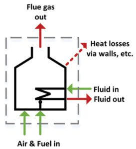
FIGURE 1. Identify input and output streams to perform a mass-energy balance for a fired heater
Stack losses
A rigorous mass-energy balance would quickly uncover that a substantial portion of the heat of combustion is escaping out the stack of the fired heater. That makes sense of course — for every 1 kg of methane burned, 18.1 kg of fluegas exit the stack — that’s a lot of mass and a lot of potential for heat to be carried out of the stack. Indeed, the fluegas temperature indicates how much heat is escaping out of the stack, and it is one of the most important variables that determines the efficiency of a fired heater. An efficient heater will have fluegas not much hotter than about 200°C, a limit set by the acid dew point. Heat recovery below that temperature is possible, but expensive, requiring special alloys to avoid corrosion. An efficient, ideal system with a fluegas temperature of 200°C has stack losses of only 16% — implying a thermal efficiency of 84% (stoichiometric air-to-fuel ratio, methane combustion). That is about as efficient as can be achieved economically. In older or less efficient systems, fluegases may be at 500°C — such a system has stack losses of 28% and a thermal efficiency of 72%. The second system would have about 17% higher fuel consumption and CO2 emissions than the first. For a 1-MW system, that amounts to $11,000/yr in additional natural gas expenses and 310 m.t./yr of CO2 emissions (assuming a natural gas price of $2/million BTU).
Air input stream
The other key stream to understand from the mass balance is the air input stream. The flowrate of this stream is not measured in most systems, so it’s generally calculated using the fluegas oxygen content. Excess oxygen in the fluegas allows calculation of how much excess air was used in the combustion process. Excess air must be warmed up to the combustion temperature, then leaves the system carrying some of the valuable heat of combustion with it. In a natural-draft fired heater, operating at 2–3% excess oxygen (measured on a dry basis) is typical, but any higher than this is a sign that the system could have its efficiency improved.
If a mass-energy balance reveals that a system has unacceptable stack losses, one solution is to add a waste-heat recovery system. The goal of this system is to reduce the fluegas temperature and use the recovered heat to displace heat demand elsewhere in the process. Particularly as systems get larger, the potential for natural gas savings quickly justifies the capital cost of a simple waste-heat recovery system.
Waste-heat recovery often uses synthetic heat-transfer fluid (HTF) systems, which are generally very cost effective, avoiding the capital and maintenance expenses of water treatment systems needed for steam. In addition, synthetic fluids are thermally stable to very high temperatures, suitable for hot fluegases, and will remain fluid at cold temperatures, so freeze protection is generally not required. For example, one widely used HTF has a maximum bulk temperature of 380°C and remains pumpable (viscosity 2,000 cSt) down to –14°C. n
References
Baukal Jr., C.E., “The John Zink Hamworthy Combustion Handbook: Volume 1-Fundamentals,” CRC Press, 2012.
Pillai, P., Meher-Homji, C., Meher-Homji, F., Waste Heat Recovery in LNG Liquefaction Plants, ASME Turbo Expo 2015.
Sponsor’s disclaimer: Although the information and recommendations set forth herein are presented in good faith, Eastman Chemical and its subsidiaries make no representations or warranties as to the completeness or accuracy thereof.
Editor’s note: The content shown here was prepared by Kent B. Fischer, Ph.D., Eastman Chemical Co., 200 S. Wilcox Dr, Kingsport TN 37660, USA