Attention to the design of bulk-solids pneumatic-conveying pipelines can help avoid conveying-system problems, such as low conveying rates, plugging, excessive wear-and-tear in the conveying line, high conveying-system pressure drop, product breakage, fines generation and product cross-contamination. This one-page reference provides general guidelines to help mitigate or avoid such problems in pneumatic conveying operations.
Materials of construction. Pipes should be made from carbon steel if contamination is not an issue. Use stainless steel for food and pharmaceutical applications. For special applications with abrasive solids, high temperatures, and so on, it is necessary to find a suitable material for the conveying line and its components.
Pressure rating.The pressure rating of the conveying pipeline should be suitable for the maximum conveying pressure of the conveying system. For most applications that have a Roots-type blower, a pressure rating of 30 psig is satisfactory. This rating corresponds to the rating of a Schedule 10 pipe. Use thicker pipes for higher-pressure applications.
Temperature rating. The temperature rating of the conveying pipeline should be suitable for the minimum and maximum temperatures experienced by the conveying line. These temperatures depend upon the ambient temperature, conveying air temperature and solids temperature.
Pipeline joints. Pipeline segments should not be welded to each other because the pipeline may need to be dismantled. Flanges can be used, but they are expensive and not easy to unbolt. So flanges should be used where the joint must be 100% leakproof. Otherwise, use easy-to-open pipeline couplings. Locate the joints for easy access. The inside diameter of the couplings or the flanges must be equal to the inside diameter of the pipe. Ends of adjacent pipe segments must be truly aligned so there is no internal protrusion and no gap between the two ends.
Pipeline internal surface. The inside surface should be clean and free of oil and rust. A smooth interior can be used, except when handling plastics that can generate so-called streamers, which are formed when a plastic particle at a high conveying velocity strikes the smooth pipe wall at a low angle of incidence. The energy of impact is enough to melt the particle surface at the point of contact and leave a thin crayon-like film mark on the pipe wall. This thin film continues to grow due to subsequent impacts, cools quickly, and peels off from the pipe wall in the shape of a streamer. The net result of streamers is plugged slide gates, feeders, screeners, mechanical conveyers and hoppers. To avoid making streamers, the inside surface of the pipeline is roughened. Although scoring is recommended for conveying systems that handle soft plastics, it has two distinct disadvantages. Pressure drop through the conveying system is higher than that in smooth pipes, and some particle attrition results because of the roughened surface.
Static charges. When handling solids that generate static charge, pipelines must be built to conduct this charge to the ground. Pipeline joints must allow this charge to flow to the ground by using static conducting jumpers across each joint. After assembly of the pipeline, check its resistance to ground, from the beginning to the end. It should not exceed 1 Ohm.
Pipeline supports. Pipes come in standard 20-ft lengths. Therefore, provide supports for the pipeline at least every 20 feet. Locate these supports to prevent any sags in the pipeline due to its weight. After installation, make sure that the pipeline is straight and not sagging. If the pipeline can expand due to high temperatures, design the supports to allow for this expansion. Locate the pipeline so that it has easy access for dismantling.
Bends. Material of construction, pressure rating and temperature rating of the bends should be the same as that of the pipe. Standard short-radius bends are not used in conveying lines because of pressure drop considerations. Studies show that long-radius bends have a lower pressure drop. Long-radius bends with a bend-radius-to-pipe-diameter ratio between 8 and 10 have a lower pressure drop (Figure 1). Some vendors have developed special bends to reduce product degradation and bend erosion.
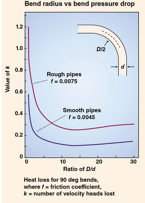
FIGURE 1. Long-radius bends in pneumatic conveying systems give rise to lower pressure drop than short-radius bends, which are generally not used in conveying lines
Air or gas supply line. Keep the length of the air or gas supply line as short as possible by locating the blower close to the solids inlet or outlet point. Minimize the pressure drop in this line by using a large-diameter line if needed. Carbon-steel construction can be used, except for in food and pharmaceutical applications. Pressure and temperature rating can be the same as that of the conveying pipe. Provide a check valve in this line upstream of the solids inlet (for pressure-type systems), or downstream of the outlet point (for vacuum-type systems) to prevent solids from backing-up into the conveying blower.
Editor’s note: The material in this column was adapted from the following article: Agarwal, A., Rules of Thumb for Pneumatic Conveying Pipelines, Chem. Eng., May 2012, pp. 51–55.