Heat transfer fluids (HTFs) provide heating and cooling of process equipment, including reactors, autoclaves, distillation columns, reboilers, mixers and dryers. HTF system designs should provide for effective system venting, both of residual water at startup and of degradation products during operation.
Water concerns
When commissioning new HTF systems (Figure 1), a primary concern should be the effects of water: new systems can be vulnerable to excessive pressures from residual water. Hydrostatic pressure tests (leak checks) conducted on the system during manufacture or onsite after maintenance can be a typical water source. Complete water removal can be hindered by traps and piping elevation changes. The best system designs provide piping installations with slopes toward strategically placed low-point drains. After water is drained, but prior to filling, the system may be further dried by purging warm, dry air (or N2) through the system’s circuits until the exiting gas dewpoint reaches –34 to –40°C, indicating moisture has been adequately dried. Close attention to the drying process will significantly reduce the time needed to reach the intended high operating temperatures at start-up.
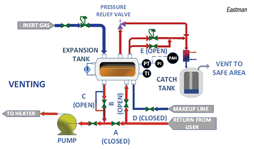
FIGURE 1. Heat-transfer fluid systems need to be vented for residual water at start-up and for fluid degradation products during operation
Removing moisture at start-up
Prior to circulation, ensure the cold liquid level of the HTF in the system is adequate. This is typically indicated by the expansion-tank liquid level instrument (Figure 1). Next, heat the liquid slowly while circulating throughout all piping circuits with the assumption that water content may be excessive. Valve A is closed, and valves B and C are open. The HTF is circulated through the expansion tank and heats to just above 100°C. This temperature forces the moisture to flash into the vapor space of the expansion tank. Valve E is open, and the ingress of inert gas sweeps the water vapors from the vapor space downstream to a catch tank or flare system. The process continues until moisture symptoms — including pump cavitation, erratic flowrate at the discharge side of the pump, and rattling, knocking and boiling sounds in the expansion tank and pipe — subside.
Once the HTF is deemed adequately dried, the fluid should be capable of continued heating to higher operating temperatures. Typical valve alignment during normal operation is for valves A and B to be open, and valves C and E to be closed. This valve placement allows a lower temperature in the expansion tank (commonly about 25% of system volume), where its thermal degradation rate is negligible.
Venting degradation products
In operation, the HTF deteriorates at increasing rates as the operating temperatures approach the bulk operating maximum for the specific HTF, altering the condition and composition of the HTF. Thermal degradation leads to the formation of both high-boiling compounds, which increase fluid viscosity and potential solids formation that increase risks of coke or fouling deposits, and low-boiling compounds that decrease the fluid’s viscosity and that have boiling points lower than the boiling range of the HTF. Additionally, increasing low-boiling content can lead to flashpoint depression by 45°C or more.
The low boilers can be managed by routine system venting. Systems are best vented only when the concentration of low boilers exceeds recommended limits based on sample analysis of the fluid.
The same procedure is followed when commissioning a new system, except higher temperatures are needed. For many organic HTFs, the venting procedure is conducted at fluid temperatures near 180 to 200°C. This temperature range supports flashing into the vapor phase and separation of the low boilers from the heat transfer fluid for removal without incurring a significant loss of the HTF components. With valve A closed and valves B and C open, all the fluid flows through the expansion tank. This process raises the fluid temperature in the expansion tank and increases the partial pressures of the low-boiling degradation products. This allows the low boilers to flash into the vapor phase, where their removal is supported by opening valve E. Inert gas can be used to efficiently sweep those vapors across the surface of the liquid and out of the vent line, where they can be condensed and collected for disposal.
Circulation through the expansion tank also ensures that all HTF benefits from reducing levels of low-boilers.
After the venting process, return to the typical valve alignment for normal operation, where valves A and B are open, and valves C and E are closed. This arrangement provides for the thermal expansion and contraction of the HTF volume to and from the expansion tank with temperature changes. Continual venting and purging is not recommended, as this can deplete fractions of the HTF itself, creating related changes in its properties, performance and life expectancy.

Editor’s note: This content was drafted by Kapil Bathla, a product development and customer technical support specialist at Eastman Chemical Co. (Kingsport, Tenn.; www.eastman.com).