Cleaning equipment surfaces is critical for processes involving biological materials to prevent microbial contamination. Clean-in-place (CIP) systems play a key role. In addition to preventing contamination, CIP systems also remove grit, scale and organic matter, which may affect process performance. This one-page reference provides information on CIP system equipment and operating considerations for bioprocessing facilities.
CIP equipment
CIP systems supply fluid to a spray device inside the vessel, which sprays the solution onto the vessel walls. A variety of spray devices are available, including static sprayballs and fluid-driven orbital cleaners. Sprayballs are high-flow, low-pressure devices often used to clean tanks smaller than 15-ft dia., while fluid-driven orbital cleaners are low-flow, high-pressure devices used for tanks greater than 15-ft dia.
Tanks. Tanks are typically constructed from 304L or 316L stainless steel. Internal welds should be ground smooth and dead spots should be minimized. Internal polishing of CIP vessels is usually not required. Detergent tanks should be equipped with agitators to ease the preparation of detergent solutions.
Pumps. There will likely be multiple unit operations and tanks using the same CIP solutions, but with different flow and pressure requirements. To address this situation, variable-speed drives (VSDs) or parallel pumps (systems with different flows and heads) may be used to meet the range of requirements. Pumps are normally centrifugal, often with VSDs. Net positive suction head (NPSH) requirements are an important consideration, due to the elevated temperatures required for some CIP fluids. Hydraulic losses for spray nozzles and equipment (heat exchangers, sterilizers and more) need to be calculated based on vendor information.
Piping. Key considerations of piping design for CIP systems include the proper design of CIP circuits, the ability to drain CIP lines, and the appropriate segregation of the CIP system from the process being cleaned. Ideally, dead legs should be no longer than two pipe diameters, and the overall system should be designed to drain completely. Lines should be sized for fully turbulent flow. The general practice is to have a velocity range of 5 to 7 ft/s. All horizontal lines should be sloped to a drain point, and low points must be equipped with drains. The minimum slope of the pipe should be at least 1/16 in. per ft. Valve selection should avoid non-drainable conditions or crevices that will not be cleaned. So-called “clean” ball valve designs are available for sizes 6 in. and less. For larger sizes, hygienic butterfly-valve designs should be considered. The tie-in point between the CIP system and the process should be either a block-and-bleed connection, or a line break.
Instrumentation. Generally recommended instrumentation for CIP processes includes the following:
• Visual sightglasses for CIP supply and return lines
• Temperature indicators on the caustic, acid and rinse-water tanks
• Conductivity transmitters in the CIP supply and return lines
• Temperature indication and control on the cleaning solution heater
• Temperature indication in the CIP return line
• Level indicators on all tanks
• Differential pressure indicators across filters and heat exchangers
• Limit switches confirming position of crucial valves
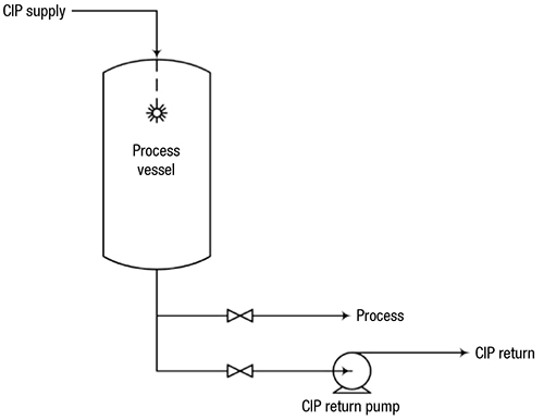
FIGURE 1. In this typical CIP system, CIP solution is sprayed into the tank to clean internal surfaces, and is drained or pumped through a separate CIPreturn line
CIP operation
A typical CIP sequence includes the following elements:
Process heel drain. A complete drain of the heel is needed to minimize waste and avoid contamination of the cleaning fluid.
Pre-rinse. The primary objective of the initial rinse is the mechanical removal of dirt. Water recovered from a later step in the CIP sequence is used for the pre-rinse step. The pre-rinse effluent stream may need to undergo a bio-deactivation process before being sent for further waste treatment.
Detergent wash. This step involves chemical cleaning to remove remaining dirt. The detergent solution is circulated through the system. The solution type and concentration should be determined by plant experience. While a 2–4 wt.% caustic solution is commonly used in this step, an acid-based detergent (or both) can also be used, depending on the type of dirt or other contaminants present.
Water rinse. A once-through rinse of clean water is typically used, with no circulation. This substantially reduces the amount of residual materials from the detergent wash step. If no acid wash is used, this water rinse step becomes the final rinse prior to either sanitization or sterilization. The rinse water should be collected for reuse as the pre-rinse fluid used in the next CIP cycle.
Acid wash. The solution used in this step may be circulated in a loop (similar to the detergent wash). This step serves two functions: to neutralize and remove any remaining caustic from the detergent wash step; and to remove any hard-water-scale deposits that may occur within the process equipment.
Editor’s note: The content for this column was adapted from Miley, B., Riley, J. and Zelmanovich, Y. Large-Scale Fermentation Systems: Hygienic Design Principles, Chem. Eng., Nov. 2015. pp. 59–65.