Proper gas sampling is essential to meet operating and regulatory objectives
Flares are used extensively in chemical process industries (CPI) facilities and petroleum refineries, to combust flammable hazardous gases. When designed and operated properly, they provide a proven mechanism to handle upset conditions in a safe manner. For instance, flares are typically used to handle the unwanted gas streams produced during upset conditions and to reduce overpressure conditions (for instance, when a pressure-relief valve or rupture disk is used to help reduce natural gas pressure in a line). Similarly, during oil-and-gas production, when natural gas is extracted with the petroleum, flaring the gas stream may be the only alternative if the infrastructure to pipe the gas to another location is not in place.
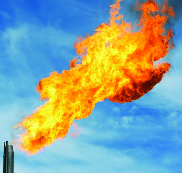
FIGURE 1. Flares are wisely used to destroy unwanted pollutants, but proper sampling is required to ensure that their own emissions meet regulatory limits
When flares are used to combust a waste stream from a process, the composition of the post-combustion exhaust gases will depend on the composition of the inlet gas received by the flare. To protect workers, neighboring communities and wildlife around the plant, and to reduce long-term impacts on the environment, a variety of state and federal requirements are in place to regulate the emissions stream. Such regulations seek to control the type and amount of specific air pollutants that are discharged from flares, and they typically require operating facilities to quantify the amount of pollutants in the exhaust stream that is ultimately discharged.
Hazardous air pollutants (HAPs; referred to as toxic air pollutants), create significant environmental concerns and potential health risks. HAPs have been associated with cancer and neurological, respiratory, and reproductive problems. In addition to health concerns, such emissions contribute to acid rain, smog, water supply pollution and climate change. The U.S. Environmental Protection Agency (EPA) currently lists 187 compounds as HAPs, many of which are commonly generated during CPI process operations [ 1].
Most HAPs are defined by the mode of production; for instance mobile sources (exhaust gases from vehicles), stationary sources (HAPS produced by petroleum refineries, power plants and other CPI facilities), and indoor sources (this includes HAPS produced by activities such as cleaning).
Regulatory framework
In 1990, the U.S. Clean Air Act (CAA) was amended to drive compliance by establishing actionable dates to achieve the reduction in the amount of HAPs released. As a result of the 1990 CAA Amendments, a new requirement of technology-based standards emerged for so-called major sources and certain area sources. Major sources are stationary sources that produce (or have the potential to produce) 10 ton/yr or more of any single chemical or 25 ton/yr or more of HAPs; area sources are stationary sources that do not follow the definition of a major source.
For these major sources of HAPs, EPA has established metrics for emissions that will determine the effectiveness of the control technology — commonly referred to as Maximum Achievable Control Technology or MACT standards [ 2]. Meeting the MACT standards doesn’t necessarily require the addition of costly emissions-control systems, such as scrubbers and thermal oxidizers; rather, in some cases, the MACT standards can be met through modifications to processes and methods that can both determine and limit the quantity of HAPs being produced.
These MACT standards constrain users to specific objective emissions parameters. MACT standards are set by EPA (for each source category) based on the emissions performance that has been achieved by the best-performing processes in that category. This level is then set as the baseline throughout the industry. The MACT standards establish the so-called National Emission Standards for Hazardous Air Pollutants (NESHAPs), which specifically exist to safeguard against emissions of HAPs from major sources.
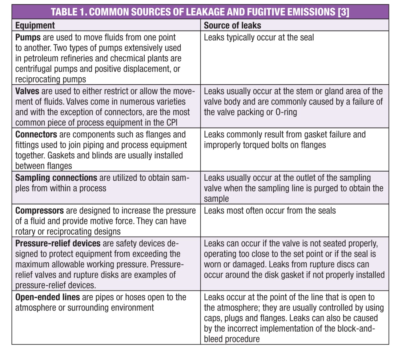
Leakage from valves, flanges, connectors and pumps are some of the leading sources for the release of HAPs and other volatile organic compounds (VOCs). According to EPA’s Leak Detection and Repair (LDAR) Best Practices Guide [ 3]: “A typical refinery or chemical plant can emit 600–700 ton/yr of VOCs from leaking equipment, such as valves, connectors, pumps, sampling connections, compressors, pressure-relief devices and open-ended lines.” Two methods are typically used to reduce emissions from leaking equipment: the use of “leakless components,” and implementation of LDAR techniques. LDAR refers to a methodology that reduces emissions from leaks by identifying the leak as it occurs and repairing it within regulated time frames. Table 1 shows common sources of leaks.
Sampling systems for flares
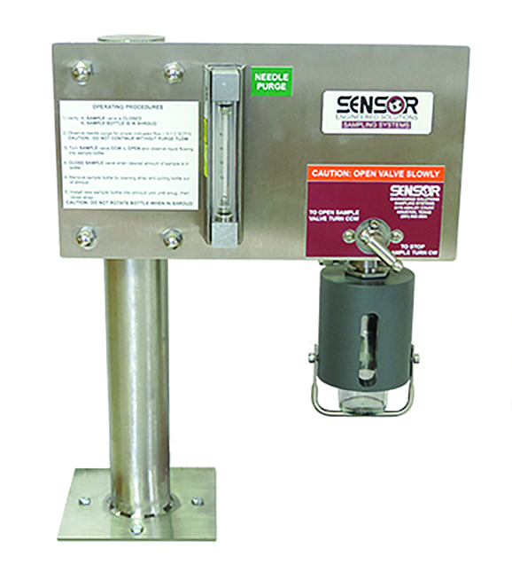
FIGURE 2. Proper sampling location and stream conditioning can help to ensure the best results
To comply with LDAR, CPI operators must quantify the amount of pollutants being released. In order to properly and safely measure pollutants from flares, a sample of flare emissions must be taken. Automatic sampling systems provide a safe and environmentally friendly way to extract needed samples. However, if not properly installed and maintained, sampling systems themselves can be a source of leaks and they too must comply with LDAR.
Sampling systems come in many different styles and configurations, and no two sampling systems are exactly alike. For example, some sampling systems can take a process sample with operator interaction, while others can automatically collect samples without any operator interaction. Each approach has its pros and cons.
Manual sampling. Manual operation allows for surveillance of the process at random (unscheduled) times. In some instances, due to variability in the operating conditions (for instance, those that are not accounted for in the early design of a sampling system), automatic sampling may in fact not allow for a true representation of the process emissions. In these cases, manual sample-collection capabilities can help to address such variability.
For example, randomly sampling when the temperature has dropped at night may show differences in samples compared to those drawn at some automatic interval. Manual operation also allows for repeated samples to account and correct for special circumstances that may have inappropriately influenced the sample collection (making it not representative of the source). For example, if a process has a new blending agent, achieving consistent operation may take several attempts to get the desired mixture. Thus, several manually drawn samples may be needed in order to verify correct measures.
Automatic sampling. On the other hand automatic sampling systems (which require no operator involvement) can look at non-standard flare events and quantify pollutants such as NOx, SO 2 and other chemicals. Such systems allow operators to set up a system for sample collection to coincide with a timed schedule or anticipated events. In addition, automatic sampling systems meet the regulatory requirements of 40 CFR 50.4 [ 4], in terms of capturing regular timed samples for SO 2 sampling in a defined time period. Appendix A of those federal regulations [ 4] define the acceptable requirements for sample probe, absorber, moisture trap, flow control and measurement, particulate-matter filters, temperature control, vacuum pump, and sample bottles that ensure that the sampling system and procedures do not negatively interfere with (and thus invalidate) sample collection.
Functions of a sampling system
Sampling systems for flares typically have the following six functions:
- To take a representative sample that is based upon the specific needs of the application
- To condition and treat a sample so that it can be used with an analyzer. This may include removing solids, moisture, or providing temperature control
- To switch sample streams in order to get multiple reference samples of a process
- To handle caustic, hazardous, and extreme environmental conditions that could adversely impact the operator or environment when attempting to extract the sample
- To allow transport of the sample for analysis
- To allow for a mechanism to dispose of the sample
As noted, sampling systems typically are of a time-based, flow-based, or volume-based scheme, with samples triggered off of events associated with these schemes. These schemes can be single action or a combination of events.
- Time-based sampling will attempt to fill a cylinder over a pre-determined amount of time, although the sample period within any given time-based sampling can vary. Time-based sampling systems are usually used when there is a continuous flowrate or the material composition is thought to be constant
- Flow-based sampling is designed to take samples in proportion to the flowrate. These systems have sample rates that are dependent on the flowrate and may increase or decrease in relation to flowrate, unlike time-based systems
- Event-based sampling systems take samples when a specific event triggers the operation; these may include an overpressure condition, changes in density, opacity or some other monitored variable
Many may argue: Why not just use a continuous analyzer to accomplish sampling requirements? As noted earlier, flares typically handle upset conditions. Therefore, under normal conditions, the flowrates, pressures or caustic concentrations may be measurable in accordance with design conditions — but when compared to an upset condition where flowrates, pressures, and so on are very high, accurate measurement may not be attainable.
Providing a mechanism to analyze the stream continuously is very costly and technically challenging. In particular, most analyzers cannot be calibrated to handle the high flow conditions while still operating at the very low range and staying in calibration. This dynamic range condition of most flares challenges many instrument manufacturers. Manual grab-sampling systems help to address these challenges. However, not all grab-sampling systems on the market today are able to comply with MACT, LDAR and NESHAP standards.
Choosing a sampling system
Historically, manual grab-sampling systems were constructed with an open tap (two-way valve) or Strahman-style valve. This approach effectively provides no vent capture or fast loop to prevent operators from taking a bad sample or exposing the sample to the environment. By comparison, today’s improved sampling systems that comply with the regulatory standards address this earlier design deficiency as part of their modern design. Specifically, effective sampling systems that ensure compliance to MACT, LDAR, and NESHAP requirements have a closed-loop design and a closed vent. Meanwhile, for operators, the following industry best practices can help to ensure the most appropriate sample collection, to ensure regulatory compliance:
- Ensure there is no condensation or other issues that could interfere with the sample
- Understand material compatibility to the process stream to ensure that the system is inert to the
process - Ensure an adequate purge system to remove residual sample material from the system
- Understand remote locations in terms of how sample collection will tie into the process line
- Choose a placement location in the process line that will get a truly representative sample
- Filter to separate liquid mixtures
- Make sample lines as short as possible
- Design to prevent pressure drop across valves and fittings
- Design to use as few fittings as possible to prevent potential leak points, and use weld fittings as needed
Sampling systems are typically custom designed and engineered at the time of order. They can involve a very complicated design in order to guarantee that they will get a true representative sample from a process. Depending on the application and the nature of the gases in the emissions stream, phase changes may occur, and if appropriate precautions are not taken, damage to expensive analyzers could result.
Meanwhile, if the samples that are collected for analysis are not truly representative of the process, inaccuracies will occur. This will lead to erroneous or misleading readings, which can have serious ramifications in terms of increased environmental pollution, and increased costs to the end user, such as loss of product or inefficient process conditions.
Minimize sample contamination
Handling the sample can be a potential point of contamination. Common errors that can lead to sample contamination (and thus misleading readings by the analyzer) result from the following activities:
- Opening the valve on the cylinder to determine if the cylinder is still under vacuum
- Opening the valve on the cylinder to verify whether there is a sample in the cylinder
- Improper selection of valves and other system
Meanwhile, some components may not be designed for use with vacuum and thus can result in leakage that brings in outside air. In addition, placement of the sampling system and its interface into the process can introduce tremendous variability. n
References
1. U.S. Environmental Protection Agency, What are Hazardous Air Pollutants? 21 July 2016, www.epa.gov/haps/what-are-hazardous-air-pollutants and https://www.epa.gov/haps/initial-list-hazardous-air-pollutants-modifications.
2. U.S. Environmental Protection Agency (EPA), Summary of the Clean Air Act, www.epa.gov/laws-regulations/summary-clean-air-act.
3. U.S. Environmental Protection Agency (EPA), Leak Detection and Repair: A Best Practices Guide, https://www.epa.gov/sites/production/files/2014-02/documents/ldarguide.pdf.
4. National Primary and Secondary Ambient Air Quality Standards, 40 CFR Part 50.4, www.govregs.com/regulations/expand/title40_chapterI_part50_section50.4
Author
Michael Bequette
Michael Bequette,P.E., is the vice president of engineering at SOR, Inc. (14685 West 105th St, Lenexa KS; 66215; Phone: 913-888-2630; Email: [email protected]). Bequette has dual undergraduate degrees, in electrical engineering and theoretical physics, from Kansas State University. He also holds an M.S. in electrical engineering from the University of Kansas, and an MBA from Park University. He has 23 years of experience in the oil-and-gas sector, as well as in the aerospace, glass, pulp-and-paper, and water and wastewater sectors. Bequette is a licensed professional engineer in multiple states, holds four patents for fiber optic product development and capacitive fault location, and is a senior member of the Institute of Electrical and Electronic Engineers (IEEE).