The pressure testing of process piping and vessels is essential in the chemical process industries (CPI). In liquefied natural gas (LNG) and other cryogenic facilities, residual water left by hydraulic pressure testing could result in operational problems if not completely removed, and complete removal of residual water can be very difficult and time consuming. Pneumatic pressure testing avoids these problems, and is frequently used for piping and vessels in which moisture is undesirable.
Hydraulic pressure testing with water, however, is much more common than pneumatic pressure testing with a gas because the stored energy of compressed gas can be roughly 200 times the stored hydraulic energy for the test pressures in the range of 100 barg. Therefore, rupture of a piping test system during a pneumatic pressure test can release much more energy. In applications where pressure testing with liquids is undesirable, such as in cryogenic piping systems and vessels, pneumatic pressure testing can only be justified when care in fabrication and in non-destructive examination of vessels and piping reduces the probability of loss of containment to such a small value that risk is acceptable. This article outlines methods for evaluating the risks of pneumatic pressure testing of vessels and piping, as well as methods for risk reduction.
Pneumatic testing
Because the atmospheric boiling point of LNG is approximately –160°C, any residual water left in the equipment, such as by hydraulic pressure testing, is undesirable. Pneumatic pressure testing is therefore frequently used for LNG and other piping and vessels in which moisture must be avoided. As mentioned, the stored energy of compressed gas is very high, so rupture of a piping test system during a pneumatic pressure test can release much energy. Damage due to rupture can result from shock waves, flying projectile fragments from the ruptured piping, and unrestrained movement of piping and equipment propelled by escaping gas. In fact, the cryogenic gas industries have experienced pneumatic pressure testing incidents in the past, sometimes resulting in serious injuries and major equipment damage.
To address the risks associated with pneumatic pressure testing, many companies attempt to limit the amount of stored energy in the test system to a prescribed maximum value by limiting the size of each test system. This approach is often impractical for high pressure piping of typical diameters because of the severe limitation that it places on the size of each test system. Consequently, this approach may result in an unreasonably large number of test systems. Attempting to isolate and test a large number of test systems may prove to be impractical. When the approach of limiting the amount of stored energy becomes impractical, an alternative approach, such as that described herein, may offer the best option. Regardless of which approach is taken, many of the considerations outlined in this article must be taken into account to safely execute high-pressure, pneumatic pressure testing.
A variety of measures can increase the safety of pneumatic testing. Of first importance are measures to ensure the mechanical integrity of the vessels and piping systems undergoing testing. These measures include design, fabrication, and inspection methods. It is also necessary to bar personnel from exclusion zones (an area where personnel are prohibited to enter) surrounding the vessel or piping system under test, and to conduct tests at night or on weekends when few people are in the vicinity of the test site.
Hazards from overpressure
Rupture of a piping system under pressure produces a blast wave. The pneumatic pressure tests planned for the piping systems for one LNG terminal were as high as 121 barg, depending on the class and size of piping under test. Pressures this high can produce a damaging overpressure in the atmosphere within the exclusion zone due to the blast wave or shock wave that results upon rupture of a piping system under test. Lower test pressures can also present significant hazards. For example, rupture of a specific 8-in.-dia. pipe segment at a test pressure of 18 barg could result in a blast overpressure of 0.5 psig (0.0345 barg) at a distance of 28 m.
Overpressure can injure personnel and damage facilities. Overpressure is the localized increase in the atmospheric air pressure associated with the passage of a shock wave.
The overpressure that accompanies failure of a piping system causes harm that is a function of the magnitude and the duration of the shock wave. Typical damaging effects from overpressures are listed below [1]:
• 0.4 psig: Limited minor structural damage to buildings
• 0.5 to 1 psig: Glass shattering with body penetrating velocities
• 0.7 psig: Minor damage to house structures
• 1 psig: Partial damage of house structures (made uninhabitable); 95% eardrum protection with ear plugs; People knocked down with potential of significant resulting injuries
Overpressure has the potential to affect most of the nearby area surrounding the piping under test. Therefore, the minimum exclusion zone in this work is defined as a zone within a radius beyond which the overpressure from rupture of the piping system under test will not exceed 0.5 psig (0.0345 barg).
Stored pneumatic energy powers the shock wave. Part of the energy that goes into compressing a gas up to the test pressure of a piping system is released suddenly if the piping system ruptures. Several different ways to estimate the theoretical amount of stored energy that is converted into blast overpressure and acceleration of fragments of the ruptured vessel have been proposed. The most common methods of estimating stored-energy release assume isentropic expansion [1–3], isothermal expansion [1,3], and/or thermodynamic availability [1,3,4]. The isentropic expansion model gives the lowest energy-release estimate; the isothermal model gives the highest estimate, which can be as high as twice that for the isentropic model; and the availability model gives an intermediate value [1].
Various equations have been developed to estimate the energy release, but most of these equations are based on the ideal gas law. Perhaps the simplest equation was initially proposed by Brode [5], and is based on the energy required to raise the pressure of the gas at constant volume from atmospheric pressure to the piping burst pressure [3]:
E = [( P1 – P o) V /(γ – 1)] (1)
Where E is the energy released upon piping system rupture; P 1 is the pipe burst pressure; P o is the atmospheric pressure; V is the volume of piping system under test; and γ is the ratio of heat capacity of gas at constant pressure to heat capacity of gas at constant volume.
The ideal gas law is not accurate and is non-conservative for the upper range of planned test pressures, so isentropic fluid-expansion energies based on measured thermodynamic properties of nitrogen gas [2] are tabulated in the summary of pneumatically tested piping spreadsheet in Table 1. Reference 2 gives an explanation of the calculation method.
| Table 1. TYPICAL BLAST AND FRAGMENT RANGES FOR PIPING SECTIONS | ||||||||||||
| OD, in. | Wall schedule | Design pressure, barg | Max. test pressure, barg | Selected length of test pipe, ft | Stored energy, MJ | Vmax, m/s | Rmax, m | Rbrittle, m | Rductile, m | Rblast, m | Exclusion zone, m | |
| Carbon-steel pipe | ||||||||||||
| 8.625 | STD | 19.6 | 22 | 57 | 1.746 | 68.6 | 480 | 192 | 394 | 30 | 30 | |
| 8.625 | XS | 91.0 | 101 | 57 | 8.53 | 123.0 | 1,543 | 617 | 891 | 47 | 47 | |
| 24 | STD | 19.6 | 22 | 88 | 22.8 | 109.7 | 1,228 | 491 | 716 | 69 | 69 | |
| 24 | 80 | 91.0 | 101 | 88 | 104.0 | 133.0 | 1,805 | 722 | 1,448 | 108 | 108 | |
| Stainless-steel pipe | ||||||||||||
| 8.625 | 20 | 19.0 | 21 | 57 | 1.751 | 76.8 | 602 | 241 | 383 | 29 | 29 | |
| 8.625 | 60 | 109.8 | 121 | 57 | 10.69 | 150.3 | 2,300 | 922 | 985 | 51 | 51 | |
| 24 | 10S | 19.0 | 21 | 88 | 22.5 | 131.9 | 1,775 | 710 | 691 | 68 | 68 | |
| 24 | 60 | 99.3 | 110 | 88 | 119.1 | 156.4 | 2,500 | 999 | 1,614 | 113 | 113 | |
| Exclusion Zone = The zone within the radius Rblast MJ = mega joules Rblast = Radius within which overpressure exceeds 0.5 psig (0.0345 barg). Rmax = Theoretical maximum projectile range based on 100% conversion of released stored energy into kinetic energy [Equation (3)]. | Rbrittle = Estimated maximum projectile range resulting from brittle fracture based on HSE (1998) report. Rductile = Estimated maximum projectile range of a blind flange resulting from ductile fracture based on Ref. 2. Vmax = Theoretical maximum velocity of projectiles based on 100% conversion of released stored energy into kinetic energy [Equation (2)] | |||||||||||
Computation of overpressure from rupture of a piping system. Published methods used to estimate the overpressure of a blast wave produced by rupture of a pressure vessel are usually based on the stored energy of the total volume of compressed gas contained within the vessel. The total gas volume has been used traditionally because the length-to-diameter ratio of the vessel is usually small enough that all of the compressed gas contributes to the blast wave. In contrast, LNG piping systems may have a large length-to-diameter ratio, and only a portion of the piping system near the initial point of failure is expected to contribute to the initial blast wave.
In one project, blast calculations for LNG piping systems were based on the stored energy available in a volume equal to a 40-ft length of pipe plus an additional 24 D (where D is pipe diameter). This assumes a longitudinal seam failure of one 20-ft pipe section (in other words, one single random length). An additional 20 ft were added to account for flow from branches in or adjacent to the failed section, and 24 D was added to account for flow originating from the header piping adjacent to the failed section. The maximum 20-ft weld-length failure was based on the premise that a propagating crack will stop when it meets the resistance of a circumferential weld. For simplicity, the same volume basis was used to evaluate piping systems fabricated from seamless pipe.
The assumptions stated above with regard to the amount of stored energy in adjacent sections of piping that contribute to overpressure in the exclusion zone and projectile propulsion must be reviewed on each individual project, with consideration given to the physical dimensions and layout of the piping.
An AIChE Center for Chemical Process Safety (CCPS) spreadsheet [3], which is based on the method of Baker [6], was used to estimate overpressure from rupture of a piping system by gas pressure. Baker’s method bases the stored energy of the gas on the Brode equation, as given in Equation (1), but then applies correlations based on experimental data. The resulting exclusion distances to keep overpressures below 0.5 psig (0.0345 barg) are summarized in Table 1 in the column labelled R blast. Overpressures were calculated for maximum test pressures that specific piping systems could experience, as well as lower increments of piping system test pressures.
A representative output from the CCPS/Baker spreadsheet [3] is presented in Table 2. The spreadsheet example in Table 2 is for a 36-in., carbon-steel, schedule 80 pipe that has broken at a test pressure of 101 barg. The resulting R blast for an overpressure of 0.5 psig (0.0345 barg) was 156 m. For comparison, the range predicted by Equation (4) (to be introduced later in this article) for fragment range for brittle fracture ( R brittle) was 908 m.
| TABLE 2. TYPICAL RESULTS FROM THE APPLICATION OF BAKER’S METHOD FOR ESTIMATION OF BLAST OVERPRESSURE [3] | |||||
| Input data: | |||||
| Vessel burst pressure: | 102 bar abs | Heat capacity ratio: | 1.4 | ||
| Distance from vessel center: | 156 m | Molecular weight of gas: | 28 | ||
| Vessel volume: | 18.84 m3 | Gas temperature: | 298 K | ||
| Final pressure: | 1.013 bar abs | Speed of sound in ambient gas: | 298 m/s | ||
| Calculated results: | |||||
| Energy of explosion using Brode’s equation for constant volume expansion: | |||||
| Energy of explosion: | 475 MJ | ||||
| TNT equivalent: | 101.4 kg TNT | ||||
| Effective energy of explosion (X 2): | 951 MJ | ||||
| Scaled distance: | 7.39 | ||||
| Interpolated scaled overpressure: | 0.0244 | ||||
| Interpolated scaled impulse: | 0.00690 | ||||
| Vessel shape: | Spherical | Cylindrical | |||
| Overpressure multiplier for vessel shape: | 1.1 | 1.4 | |||
| Corrected scaled overpressure: | 0.0268 | 0.0341 | |||
| Actual overpressure: | 0.0272 bar | 0.0346 bar | |||
| 0.39 psi | 0.50 psi | ||||
| Impulse multiplier for vessel shape: | 1 | 1 | |||
| Corrected scaled impulse: | 0.0069 | 0.0069 | |||
| Actual impulse: | 39.3 kPa – ms | 39.3 kPa – ms | |||
Exclusion zones were chosen to insure that overpressures from rupture of the piping system could not exceed 0.5 psig (0.0345 barg) at the boundary of the exclusion zone radius, regardless of the mode of fracture of the piping system.
Hazards from projectiles
Rupture of a piping system may occur due to either ductile fracture or brittle fracture. Under the planned test conditions for one LNG project, it was determined that the carbon-steel systems might exhibit ductile or brittle fracture and that the stainless-steel piping systems might exhibit ductile fracture. The number of fragments and the methods of estimating the velocities of the resulting projectiles differ for brittle and ductile fracture.
Rupture of a piping system under pressure may produce projectiles.Here are Mannan’s [1] introductory remarks on fragmentation resulting from either brittle or ductile fracture:
“The number of missiles formed in an explosion involving rupture of containment varies widely. At one extreme is the bursting of a weapon such as a high explosive shell or grenade, which normally gives a large number of fragments. Large numbers of missiles are also produced by fragmentation of a gas-filled pressure-vessel. At the other extreme is the ejection of a single item, such as a valve component, due to failure in a high pressure system.
Of particular interest here is rupture of a pressure vessel. This may involve either brittle or ductile fracture. … In general, failure is more likely to be ductile. Ductile failure does not usually produce missiles, but if it does they are likely to be small in number but may have the potential to do severe damage. It is brittle fracture which is most likely to produce failures in which quite a large number of fragments are generated.”
Theoretical maximum velocity and range of projectiles.One method of estimating the theoretical maximum velocity is to assume that the pressure energy stored in a piping system is completely converted into kinetic energy of the piping system under test [2–3]:
E = ( m × v 2)/2 (2)
Where E is the energy released upon piping system rupture; m is the total mass of projected piping system fragments; and v is the velocity of each fragment of the piping system.
The theoretical maximum range (neglecting air friction) is then calculated assuming that the projectiles are launched at a 45-deg angle from horizontal. An angle of 45 deg is the optimum angle for the maximum projectile travel distance. Equation (3) is based on Newton’s second law of motion and Newton’s law of gravitation; its derivation is found in many college-level physics textbooks:
Rmax = v 2/ g (3)
Where R max is the theoretical maximum range; and g is the acceleration due to gravity. Distances calculated with this conservative method are very large, as can be seen in Table 1. Calculated values range from 35 to 2,497 m.
The Health and Safety Executive (HSE) report [ 2] indicates that only about 40% of the pressure energy would be translated into kinetic energy for brittle fracture of a cylindrical container during testing, and less energy would be translated into kinetic energy for ductile fracture of the container. Thus for brittle fracture, Equation (4) gives a better estimate of the theoretical range of missiles:
R brittle = 0.4 × R max (4)
Brittle fracture ranges estimated with Equation (4) are tabulated in Table 1 in the column labeled R brittle.
Predicted velocities and ranges of projectiles from brittle fracture.Naturally, most fragments would not launch at the optimum angle, and air friction would reduce the range as well. Finally, when two or more fragments result from rupture of a piping system, the resulting projectiles will usually have a distribution of sizes and initial velocities.
Baker [6] developed methods to estimate fragment ranges taking shape and air friction into account. Spreadsheets developed by the CCPS [ 3] to apply these methods were used to develop the results shown in Table 3 for a 20-in., carbon-steel, schedule 80 pipe that has broken into two fragments at a test pressure of 101 barg. Each of the two fragments is a section of pipe, flying end-wise with a lift-to-drag ratio of zero. For comparison, the range predicted by Equation (4) is 709 m. Representative values calculated with Equation (4) in Table 1 are used as estimates of the maximum range of missiles from brittle fracture.
| TABLE 3. TYPICAL FRAGMENT RANGES FOR BRITTLE FRACTURE BY METHOD OF BAKER [6] | ||||
| Fragment mass fraction | Fragment mass, kg | Exposed area, m2 | Velocity, m/s | Range, m |
| 0.1 | 186 | 0.2027 | 109 | 1,093 |
| 0.2 | 372 | 0.2027 | 80.5 | 597 |
| 0.5 (2 of equal size) | 930 | 0.2027 | 64.4 | 429 |
| 0.6 | 1,117 | 0.2027 | 63 | 419 |
| 0.7 | 1,303 | 0.2027 | 62.2 | 401 |
| 0.8 | 1,489 | 0.2027 | 61.8 | 399 |
| 0.9 | 1,675 | 0.2027 | 61.5 | 397 |
Field data on projectiles from ruptured vessels. Mannan [1] presents observed fragment ranges from boiling-liquid expanding vapor explosions (BLEVEs) of liquefied petroleum gas (LPG) vessels (Figure 1). Although most fragments traveled 700 m or less, one fragment traveled about 1,000 m (see Curve “d” for spherical vessels). A BLEVE might result in substantially larger distances than a compressed gas explosion of the same container at the same burst pressure. This is because the liquid-filled vessel contains a much larger mass of liquid and a significant fraction of that liquid will vaporize (boiling liquid) upon vessel failure. The vapors will then burn and expand even further. Although the LPG vessels probably failed at pressures well below the test pressure of 100 barg, the BLEVE mechanism may account for the large projectile ranges relative to those expected for pneumatic pressure testing. Although Mannan [1] does not indicate the failure mechanism in these incidents, it was probably ductile failure because the LPG vessels failed during external fire exposure.
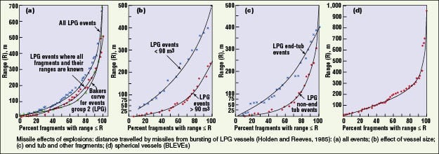
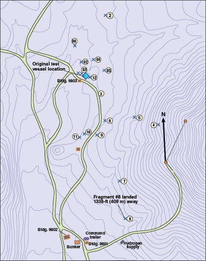
Figure 2 is a map of the fragment location from a test at Sandia National Laboratories [7]. An 8:1 scale model of a nuclear-reactor containment vessel with a design pressure of 40 psig (2.76 barg) was pneumatically pressurized to failure with nitrogen gas. The vessel failed at a pressure of 195 psig (13.4 barg). Figure 2 shows the locations of twelve resulting fragments, as indicated by Xs, and gives identification numbers for them. Fragment number 8 traveled 408 m (1,338 ft) from the original location of the test vessel. Baker [7] reports that the failure was ductile.
Range of projectiles from ductile fracture. HSE Guidance Note GS4 [2] gives the following equation for calculation of maximum fragment velocity for ductile fracture of a container:
v 2 = (2 × d × P 1 × A)/ m f (5)
Where d is the diameter of hole left behind (Note: For small fragments such as plugs or small closures, it should be assumed that d is twice the diameter of the hole left behind); A is the area of ejected fragment; and m f is the mass of the fragment.
Assuming an optimum projectile-launch angle of 45 deg, the maximum range of the fragment is then calculated with Equation (6):
Rductile = v 2/ g (6)
These equations lead to projectile ranges similar in magnitude to brittle fracture, but the projectile ranges are highly dependent on the size and shape of the ejected fragment. For example, for a 100-barg test pressure leading to the failure of a 1.5-in., 600-lb nozzle, an exclusion zone of 22.4 m was calculated in a different study. That work was based on assuming that the nozzle fragment included [(Boss flange) + (0.3 m pipe) + (gate valve) + (flange) + (blind flange)].
Lighter fragments (for example, the blind flange) would fly farther. Table 1 presents values of R ductile calculated with Equation (6) for blind flanges. (Blind flanges were chosen to calculate R ductile because their size is well-defined for a given pipe class and size, and because they project a large area that is exposed to the escaping gaseous energy.) These distances are much larger than those in the different study cited above, and similar in magnitude to those calculated for brittle fracture using Equation (4).
Note that fragment ranges for small fragments can be significantly larger than those for blind flanges.
Probability of personnel injury by projectiles. Because of the potentially large ranges of projectiles from rupture of a piping system, the choice of exclusion zones for pneumatic testing could be quite large if they were based on these potential fragment ranges. However, most fragments from rupture of a piping system will fall near their original location (See Figures 1 and 2). One rough approximation proposed here regarding the distribution of fragments is to assume an exponential decay with distance.
Probability of a fragment at radius r = e–2 r/R (7)
Where R is the characteristic range.Then, the probability of a fragment falling outside an exclusion zone (Z) becomes:
Probability of a fragment falling outside Z = ∫ e–2 r/R d (2 r/R) (8a)
And evaluating the integral between 2 Z/R and infinity:
Probability of a fragment falling outside Z = e–2 Z/R (8b)
If the exclusion zone ( Z) is chosen to be equal to the characteristic range R (as calculated in Table 1 for the appropriate failure mode), then the probability of a fragment falling outside the exclusion zone is e–2 or 0.135 or 13.5%. The total number of fragments falling outside the exclusion zone would thus be 13.5% of the total number of fragments formed.
The problems in applying this concept to a quantitative estimation of the probability of a person being injured are: a) accurately estimating the number of fragments formed when a piping system ruptures; b) accurately estimating the characteristic range R; and c) accurately estimating the number of people in the area.
The probability of one injury during a pneumatic test at a facility depends on the probability of failure during the test, and the probability of injury during any single failure.
Probability of injury during a pneumatic test = (Probability of piping failure) × (Probability of injury outside exclusion zone, Z when pipe fails) × (Probability that a fragment falls outside Z) × (Number of fragments formed by failure) (9)
The Gas Research Institute sponsored a study of human and equipment failure rates in the LNG industry by Atallah, and others [8]. Its data include failure rates of piping systems. Applying data from plant operation to pneumatic testing prior to initiation of plant operation is questionable, but might be roughly indicative of the probability of a failure during test. Atallah, and others [ 8] presented a mean time between failure (MTBF) for LNG piping systems of 5.8 × 108 ft-hr.
Probability of one LNG piping system failure during pneumatic testing = [(Number of pneumatic test systems) ×(Length of pipe per system)× (Duration of each pneumatic test)]/ (MTBF) (10)
The test duration used in one project was approximately 2 h (1 h at lower pressures, 15 min at P design, 30 min at P test, and 15 min at P design).
Assuming 200 LNG pneumatic-test systems and an average of 300 ft of pipe per test system, the probability of failure of one LNG piping system among all those tested during LNG pneumatic testing is approximately 1 in 5,000. Because of the “bathtub” shape of failure rate data, the probability of failure of an LNG piping system during test may be somewhat higher. (Graphs of failure rates versus time typically resemble a bathtub, with a high initial failure rate, then a constant and low failure rate during the expected life of the product, and finally an increasing failure rate at end-of-life.)
In the unlikely event of a failure of an LNG piping system during pneumatic pressure testing, all personnel would be protected from blast overpressure by the conservative exclusion zones in use. Although one or more fragments might fall outside the exclusion zone, most of the fragments would fall within the exclusion zone, and the probability of a person being struck by a fragment is very low.
A confidential and detailed quantitative risk assessment of a proposed pneumatic test of a 6-km LNG pipeline also yielded the conclusion that the risk of pneumatic testing would be acceptably low.
When rigorous precautions have been taken to establish safe testing procedures and to ensure the integrity of the piping systems being tested, the risk of pneumatic pressure testing of selected LNG piping systems can be made acceptable. As a minimum, rigorous attention needs to be given to the essential considerations listed in the box, Precautions in pneumatic pressure testing.
Safe exclusion zones
The shock wave from rupture of a piping system under test could affect much of the immediate area surrounding the test, so the exclusion zone for the test should be at least large enough to keep the overpressure from exceeding the criterion selected in this article of 0.5 psig (0.0345 barg). The intent is that only those people conducting the pneumatic pressure test would be allowed to enter the exclusion zone and then only under carefully prescribed conditions.
Conversely, projectiles resulting from fragmentation of a piping system will be relatively few in number, and most would fall relatively close to their origin. The remaining few would be distributed over a comparatively large area and would have only a very low probability of hitting a person. These considerations form the basis of the logic of using only overpressure considerations in order to establish exclusion zones.
This article was presented at the 10th Natural Gas Utilization Symposium and the Spring National AIChE Meeting, March 21–25, 2010, San Antonio, Tex.
References
1. Mannan, S. M., ed., “Lee’s Loss Prevention in the Process Industries”, 3rd ed., 3 volumes, Elsevier Butterworth-Heinemann, Oxford, U. K., 2005.
2. Health and Safety Executive, “Safety in Pressure Testing”, Guidance Note GS4, UK Health and Safety Executive, Sudbury, Suffolk, U. K., 1998.
3. Center for Chemical Process Safety, “Guidelines for Consequence Analysis of Chemical Releases”, American Institute of Chemical Engineers”, New York, N.Y., 1999.
4. Crowl, D. A., Calculating the Energy of Explosion Using Thermodynamic Availability, J of Loss Prevention in the Process Industries, vol. 5, pp. 109–118, 1992.
5. Brode, H. L., Blast Wave from a Spherical Charge, Physics of Fluids, vol. 2, p. 217, 1959.
6. Baker, W. E., and others, “Explosion Hazards and Evaluation”, Elsevier, New York, N.Y., 1983.
7. Baker, W. E., Post-Test Assessment of Blast and Fragment Effects of Explosive Failure of a Large Steel Containment Shell Model During Pneumatic Testing, Conference Paper, pp. 289–296, 1985.
8. Atallah, S., and others, Reduction of LNG Operator Error and Equipment Failure Rates, Gas Research Institute Report No. GRI-90/0008, Chicago, Ill., 1990.
Authors

Victor H. Edwards is director of process safety for Aker Solutions Americas Inc., (3010 Briarpark Drive, Houston, TX 77042; Phone: 713-270-2817; Fax: 713-270-3195; Émail: [email protected]). In his 27 years with Aker, Edwards’ experience includes process engineering, safety management and process, biochemical and environmental technologies. He has received numerous accolades in the areas of safety and environmental engineering, including five DuPont awards, and has contributed extensively to the engineering literature. His earlier experience includes assistant professor of chemical engineering at Cornell University, an assignment at the National Science Foundation, pharmaceutical research at Merck, alternate energy research at United Energy Resources, visiting professor at Rice University and process engineering at Fluor Corp. Edwards earned his B.A.Ch.E from Rice University and his Ph.D. in chemical engineering from the University of California at Berkeley. A registered professional engineer in Texas, he is an AIChE Fellow, and a member of ACS, AAAS, NFPA, NSPE, and the N.Y. Academy of Sciences.
Don Sanford is a senior engineering technician with Aker Solutions Americas Inc. In his 15 years there, Sanford’s experience includes piping materials, piping fabrication, testing, installation, coatings, thermal-insulation and heat-tracing specifications. Prior to working with Aker, Sanford worked with Stearns Rogers, Black & Veatch, KBR and Raytheon.

Brooke Bonstead is a mechanical engineer for WorleyParsons (575 North Dairy Ashford, Houston, TX 77079). In her five years in the oil-and-gas EPC industry, Bonstead’s experience includes serving as a requisitioning engineer for various mechanical packages for both onshore and offshore LNG regassification and offshore oil production facilities. She earned her B.S. from Texas A&M University and is a registered EIT in the state of Texas.

Larry Skoda is a principal piping engineer (Email: [email protected]; Phone: 713-372-7174), who has worked for more than thirty years as a pipe stress and piping engineer for companies designing facilities for oil and gas, petrochemical and power companies. His most recent such employer was Aker Kvaerner in Houston. Skoda is a professional engineer who graduated with a B.S.M.E. from University of Texas at Arlington. He was a contributor to the piping section of “Perry’s Chemical Engineers’ Handbook”.