Emergency pressure relief is a dynamic event with rapidly changing physical properties. Available utilities aren’t always capable of handling the complex calculations commonly needed in the CPI. A simplified calculation technique is presented to address the issue of valve sizing for external fire scenarios
Traditional pressure-relief devices are, at times, unable to protect vessels at the elevated temperatures experienced during fires. As witnessed by numerous examples throughout history, loss of containment and the subsequent explosions that may occur with an over-pressurized system can lead to catastrophic results in terms of equipment damage, monetary loss, environmental impact and even human casualties. The importance of adequately sizing depressurization capacity for an emergency situation cannot be overemphasized. Here, a simplified, but sufficiently accurate, method to ensure the adequacy of depressurizing systems for external fire scenarios is introduced.
The accepted industry standard for vapor depressurizing philosophy is the American Petroleum Institute (API) Recommended Practice (RP) 521 “Guide for Pressure-Relieving and Depressurizing Systems” (Fourth Edition, March 1997). This reference suggests reducing system pressure to 100 psig or half the vessel design pressure (whichever is lower) within 15 minutes after initiation of an external fire-driven depressurizing event. The total mass of vapor to be relieved in the allotted time can be estimated from the sum of three parts: vapor-density decrease with decreasing pressure; vapor generation from heat input due to fire; and liquid flash. Although API RP 521 outlines clear methods for solving for these three mass values, no clear guidance is given on ascertaining a transient depressurizing rate and thus, the document does not speak directly with respect to valve sizing. At the same time, commercial simulators with depressurizing utility options lack, to some degree, adequate representation of actual installations in the chemical process industries (CPI), as these simulators are unable to directly handle depressurizing from multiple vessels via a single valve.
The proposed calculation method presented in this article attempts to solve the problem of valve sizing for depressurization without the use of dynamic analysis or a computer-simulated depressurizing utility.
Traditional calculations
During an external fire event, excessive vessel-wall temperatures can result in vessel failure well before a pressure increase will trigger the opening of a pressure relief device. And, even if a pressure relief device does open, vessel-wall temperatures may continue to increase during the event. It is wise, therefore, to install a properly designed depressurization system to reduce vessel-wall stress levels, remove energy, and decrease inventory.
As mentioned, API RP 521 suggests reducing system pressure to 100 psig or half the vessel design pressure (whichever is lower) within 15 minutes after initiation of an external fire-driven depressurizing event. There has been extensive discussion as to the appropriate final pressure (also called the depressurized level) in such an event. The first edition of API RP 521 (September 1969) stated that a depressurized level equal to half the vessel design pressure had previously been used, but because of modern, high-pressure processes, the lesser of 100 psig or half the design pressure should be used in order to minimize the amount of stored energy in the system. The second edition of the recommended practice (September 1982) declared that both 50% of design and 100 psig are used in the industry as depressurized levels, but this version stated (essentially) that the 100-psig level might be impractical for systems that operate at very high pressure. It also noted that although the 100-psig depressurized level would permit more rapid control in the event of a leak, depressurizing to half the design pressure is within an acceptable margin of safety in many cases.
The current guidance offered in the fourth edition of API RP 521 (March 1997) states that the depressurized level should be 100 psig or half the vessel design pressure, whichever is lower, in order to permit more rapid control of a leak in the system. More recently, evidence shows that depressurizing to half the vessel design pressure may not provide sufficient creep-rupture protection in all cases, thereby suggesting that perhaps a lower depressurized level would be appropriate in some instances.
Although API RP 521 outlines methods for estimating the three parts that make up the total vapor mass to be relieved in the allotted time (vapor-density decrease with decreasing pressure, vapor generation from heat input due to fire, and liquid flash), no clear guidance is given to ascertain a transient depressurizing rate. Essentially, the conclusion from the document is that a mass of vapor needs to be relieved in a certain amount of time and that a depressurizing valve and disposal system must be sized adequately to accomplish this feat.
Alternative method
A depressurizing scenario is a dynamic event with rapidly changing physical properties, so depressurizing calculations can quickly become very complex. Some commercial process simulators contain depressurizing utilities to handle these scenarios, but often the availability of such tools is sparse. In addition, commercial depressurizing utilities aren’t always capable of handling the complex installations commonly seen in industrial applications. A major stumbling block is the inability to handle multiple vessels that depressurize through a single valve.
For such installations, required quantities of vapor to be relieved (due to fire, vapor-density decrease, and liquid flash) should be evaluated individually for each piece of equipment. API RP 521 states:
“If the system to be depressurized includes more than one vessel, the vapor quantities for each vessel under all three occurrences should be calculated, especially if different molecular weights, latent heats, insulation thicknesses, and vaporization temperatures are involved.”
Calculated vapor mass quantities for each individual piece of equipment are then added to obtain the total vapor mass required to be relieved. A detailed example of such a calculation involving a typical hydrotreater reactor loop is analyzed later in the discussion.
The method for determining the required vapor mass to be relieved due to external fire as presented above (in conformance with API RP 521) is an estimation that may be affected by changes in residual liquid composition and levels (either liquid swell due to increasing temperature or liquid-level depletion due to boil-up). Time dependent quantification of residual liquid level and composition would require a dynamic analysis. For the purposes of this analysis, liquid composition and level are assumed to be constant as the effects of a rigorous, dynamic analysis on the final result are considered negligible. For cases in which liquid swell, level depletion, and composition change with time are thought to significantly affect the final vapor rate or composition (such as a case considering a large mass of liquid with a wide boiling-point range), a semi-dynamic approach can be used in which the required mass to be depressurized is calculated at predetermined time steps. In this manner, liquid swell, level depletion, and composition change with time can be accounted for by adding the mass values for each time step.
After the detailed calculation for the required mass to be depressurized, an analysis for valve sizing must be performed. The difficulty of accurately modeling the fluid quantity passing through a depressurizing valve must be emphasized. Fluid compositions and properties are in constant flux during a depressurizing event due to a swift decrease in system pressure, as well as energy additions to the system from the fire. To simplify depressurizing calculations without the use of a commercial depressurizing utility or the use of dynamic analyses, a two-point exponential fit (one at starting pressure, one at final pressure) is proposed to model the decay of depressurizing rate with time. A check of valve adequacy may then be accomplished by integrating the exponential expression and comparing this theoretical mass of vapor to the previously calculated required mass to be relieved.
To obtain an initial depressurizing rate, the total mass of fluid (liquid and vapor) in the system at the initial depressurizing condition should be mixed to obtain an initial settle-out pressure, temperature, and vapor composition. The initial depressurizing condition is usually taken as the normal operating pressure and temperature, but a higher pressure (90% of design pressure, for example) can be used to account for a delay in operator intervention. If settle-out is not expected to occur before the depressurizing commences, the temperature, pressure, and composition of the vapor at the depressurizing-valve location can be used for the initial condition. Based on vapor properties at the initial condition, the initial depressurizing rate can be found by using a simple control-valve equation.
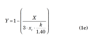
An example of a typical flow equation for a control valve is presented below:
where,
(whichever is less)
In the above equations,
W = mass flowrate, lbm/h
Cv = valve sizing coefficient (based on the number of gallons of water at 60°F that can be passed at 1 psi pressure drop)
Fp = piping geometry factor
xt = terminal pressure drop ratio
P1 = upstream pressure, psia
Pâ‚‚ = downstream pressure, psia
MW = vapor molecular weight
Z = vapor compressibility
T = vapor temperature, °R
Y = expansion factor
k = ratio of specific heat at constant pressure divided by the specific heat at constant volume
For most depressurizing cases, the downstream pressure in the equation can be assumed as a minimal value, thereby modeling the depressurization as critical flow into the disposal system. This assumption is based upon the typical industry installation of emergency depressurizing valves in which the valve itself is the limiting flow restriction in the system that discharges to a larger diameter network or disposal header. It should be noted that the critical flow assumption should be scrutinized in situations where multiple releases are sent to the disposal header and when the outlet piping run from the valve contains a long run of small diameter pipe (relative to the depressurizing-valve body size).
Another typical installation found in industry includes a restriction orifice at the depressurizing valve to limit flow into the disposal system. In this case, the limiting flow element is expected to be the restriction orifice. For installations of this nature, an orifice-flow calculation should be used in lieu of the control-valve calculation called for in this article.
To obtain a final depressurizing rate, the initial mixture of fluid (total mass of fluid in the system at the initial condition used in the calculation of the initial depressurizing rate) should be flashed adiabatically to the final pressure (100 psig or half the vessel design pressure, whichever is lower). The total heat that is added to the system due to fire should be applied to the fluid, and any heat loss that is assumed to occur (through the pipes and vessel walls to atmosphere) can be included here as well. It should be noted that no credit for normal process cooling duties should be taken per API RP 521, even if flow to the cold side of an exchanger is expected to continue (such as cooling-water flow to a trim condenser). API RP 521 states, “all normal flows to the system are assumed to cease”. This is interpreted to include cooling-water flows to the unit that would have the effect of neutralizing the fire-heat input to the system. Based on vapor properties at the final condition, the final depressurizing rate can be found by using a simple control-valve equation.
Is an exponential fit suitable?
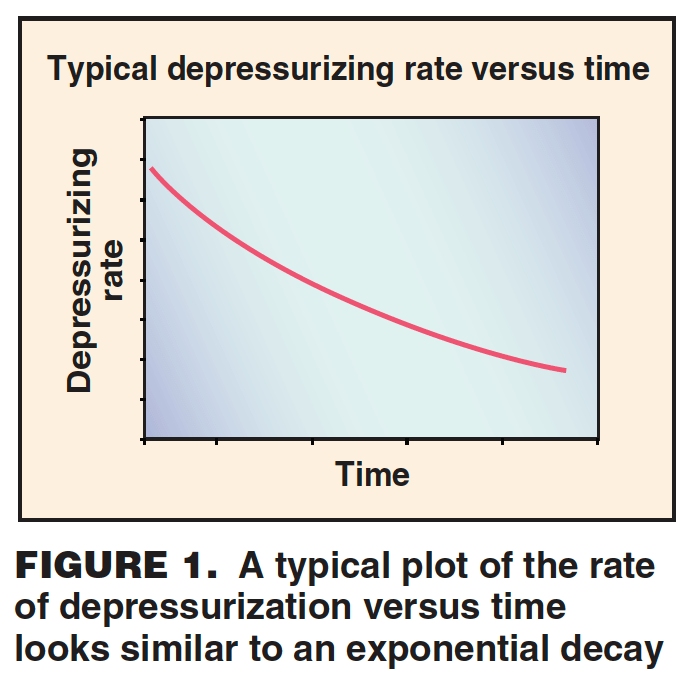
Because of the continuous decrease of pressure in the process vessel (such as pressure upstream of the depressurizing valve) during a depressurizing event, depressurizing mass rate continually decreases due to the loss of driving force. A typical graph of depressurizing rate versus time looks quite similar to a graph of exponential decay (see Figure 1). In fact, an exponential curve can fit with relatively close precision to these curves. To demonstrate, an example is presented below in which the depressurization of a vapor-filled vessel is rigorously analyzed.
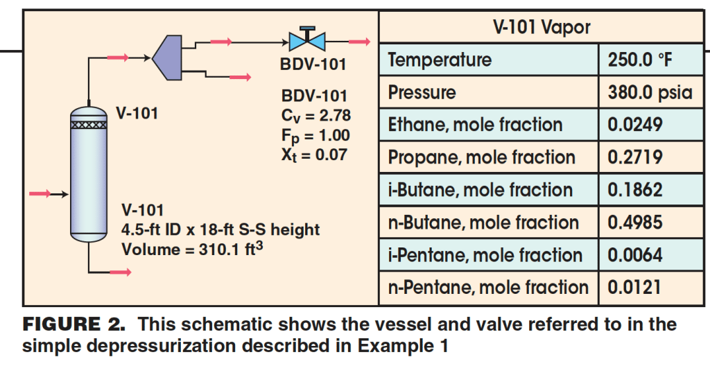
Example 1. Vessel V-101 is a large, horizontal vessel filled with light hydrocarbon vapors (Figure 2). The vessel is to be depressurized from its normal operating pressure of 365.3 psig (380 psia) to 100 psig (114.7 psia) in 15 minutes. The vessel has the following properties:
Dimensions: 4.5-ft inside diameter (I.D.) × 18-ft seam-to-seam (S-S) length
Volume: 310.1 ft3
Operating pressure: 380 psia
Operating temperature: 250 °F
Vapor fraction: 1.0
Enthalpy: –917.13 Btu/lbm
Composition (mole fractions): ethane (.0249), propane (.2719), isobutane (.1862), n-butane (.4985), isopentane (.0064), n-pentane (.0121)
Vapor MW: 53.87
Vapor compressibility: 0.649
The blow-down valve (BDV), BDV-101, has the following coefficients associated with it:
Cv = 2.78
Fp = 1.0
xt = 0.70
Assume that depressurization of this system starts from the operating pressure and temperature and that no external fire effects are included. The rigorous analysis assumes a constant specific enthalpy in the vessel (in other words, no heat is lost to surroundings) during the course of depressurizing. Flow through BDV-101 is calculated from Equations 1a through 1c.
For each time step (15 seconds was used for this analysis, resulting in a total of 60 steps), a new system enthalpy and system mass are determined based on the calculated rate exiting the vessel (via the depressurizing valve). Then, iterative pressure-enthalpy flashes are required to find a pressure and temperature yielding a match with the calculated system density (new system density based on the mass left in the system divided by constant system volume). The process was repeated 60 times for this relatively simple case. The laborious nature of the calculation should be emphasized. Results are presented in a graphical representation of the fall-off of depressurizing rate with time in Figure 3.
Using the initial (W = 3,887.8 lb/h, t = 0 hours) and final (W = 1,822.7 lb/h, t = 0.25 hours) data points from the rigorous analysis, an exponential of the following form is fit to the results:
y = 3,887e–3.0302x (2)
Figure 3 shows the fit plot alongside the rigorous results. At a cursory glance, it is seen that the exponential fit matches quite well with the rigorous results. The mean value of the rigorously determined rates was found to be 2,175.6 lbm/h. The non-linear regression (R2) was calculated to be 0.999, showing an excellent data fit.
Rigorous calculations showed that the total mass relieved in 15 minutes is 682.6 lbm. In the exponential fit (Equation 2), y represents the mass flowrate (dm/dt) and x represents time. By integrating the exponential fit from 0 to 15 minutes, we get the calculated mass relieved in 15 min (0.25 h) from the proposed data fit.
with the result of the integration as:
Integration yields a result of 681.3 lbm. The result shows a percent error of less than one (0.19%).
This example illustrates that the shortcut method of fitting an exponential to simulate the decay of depressurizing rate with time also yields close correlation with rigorously calculated results. The shortcut results in a significant reduction in calculation and effort, and eliminates reliance on commercial process-simulation software in calculating dynamic depressurizing events.
Applying the suggested method
Having demonstrated the suitability of an exponential fit to depressurizing scenarios, another example shows how the timesaving method can be readily applied to common installations found in industry.
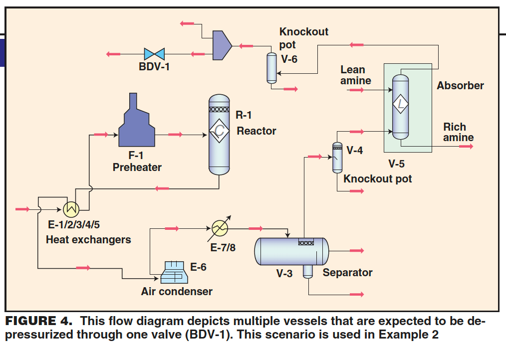
Example 2. A 6-in. valve (Cv = 300, Fp = 1.0, xt = 0.7) is installed to relieve the pressure in a hydrotreater reactor loop including the reactor vessel, fired preheater, shell-and-tube sides of five feed/effluent heat exchangers, aerial effluent condenser, trim effluent condenser, high-pressure (HP) separator vessel, absorber knockout pot, amine absorber, and recycle-compressor knockout drum. The question posed is this: Is the valve adequately sized to depressurize the reactor-loop contents from normal operating conditions to 100 psig in an external fire scenario affecting the compressor knockout drum, absorber knockout pot, and amine absorber?
A flow diagram of the hypothetical process is presented in Figure 4. The depressurizing valve (BDV-1) is located downstream of the recycle-compressor’s overhead knockout drum (V-6), or on the recycle-compressor suction line.
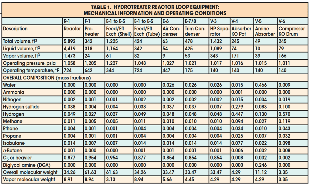
Details about the equipment and operating conditions are presented in Table 1. Following the procedure described earlier, the first step in answering the question posed is to determine the total required mass of vapor to be vented. To do this, each individual piece of equipment is considered separately. For each piece of equipment, three contributions to the total vapor mass to be relieved are considered: vaporization due to heat input from external fire, vapor-density decrease due to reduction in pressure, and liquid flash due to pressure reduction. As noted earlier, the required vapor mass to be relieved due to fire-heat input assumes a constant liquid level and liquid composition during the depressurizing event.
The equations (presented in API RP 521) used to solve for the three parts are:
1. Vaporization due to fire:
where,
Q = 21,000A0.82 (5a)
Wf = vapor flowrate to be vented due to fire considerations, lbm/h
t = depressurizing time interval, h (usually assumed to be 0.25 h)
Q = heat input to vessel due to external fire, Btu
A = exposed wetted area of vessel, ft2
λ = liquid latent heat of vaporization, Btu/lbm
2. Vapor-density decrease due to reduction in pressure:
Wd = vapor flowrate to be vented due to vapor-density reduction considerations, lb/h
t = depressurizing time interval, h (usually assumed to be 0.25 h)
V = volume available for the vapor, ft3
P = absolute pressure, psia
M = vapor molecular weight
Z = vapor compressibility
T = vapor absolute temperature, °R
a = original condition at start of depressurizing
b = final condition at end of depressurizing
3. Liquid flash due to pressure reduction:
Wv = vapor flowrate to be vented due to liquid flash, lbm/h
t = depressurizing time interval, h (usually assumed to be 0.25 h)
Q = heat input to vessel due to external fire, Btu (see Equation 5a)
λ = average liquid latent heat of vaporization, Btu/lbm
a = original condition at start of depressurizing
X = weight fraction of initial liquid in the system vaporized as a result of depressurizing
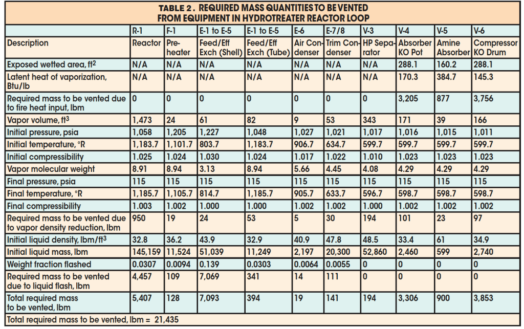
The results for required mass to be relieved for each individual piece of equipment in the loop are presented in Table 2. Note that the external fire is assumed to affect only the compressor knockout drum, absorber knockout pot, and amine absorber. The calculated mass to be relieved was found to be 21,435 lbm. Mixing of the residing fluid in the process yields the following vapor properties at the initial depressurizing condition:
Pressure = 1,011 psia
Temperature = 501.1 °F
Molecular weight = 10.132
Compressibility = 0.975
k = 1.37
From Equations 1a–1c, the depressurizing rate at the initial condition was calculated to be 335,792 lb/h assuming negligible downstream pressure in the disposal system. Using the same initial composition, the vapor properties at the final condition were found to be:
Pressure = 114.7 psia
Temperature = 476.2 °F
Molecular weight = 10.132
Compressibility = 0.996
k = 1.32
The depressurizing rate at the final condition was calculated to be 37,486 lb/h assuming negligible downstream pressure in the disposal system.
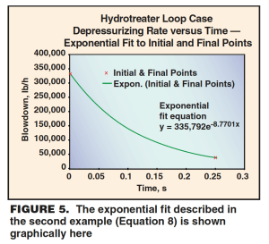
Using these two rates and times (335,792 lb/h; 0 h), (37,486 lb/hr; 0.25 h) as data points in an x-y plane, an exponential fit of the following form is obtained (Figure 5):
y = 335,792 · e–8.7701x (8)
As in Equation 2, y represents mass flowrate (dm/dt) and x represents time. An integration of Equation 8 gives the mass relieved,
with the result of the integration as:
The final result is 34,013 lbm. Because the required mass to be relieved (21,435 lbm) is smaller than this calculated value, the valve is adequately sized for the external fire scenario.
Conclusion
The shortcut method of approximating depressurizing rate decay with time by fitting initial and final depressurizing rates to an exponential curve gives good correlation to rigorously calculated results. This time saving method can be applied to verifying the adequacy of existing emergency depressurizing installations for external fire scenarios. This method can also be applied to more complex installations typically seen in industry, thereby reducing dependence on process-simulator depressurizing utilities.


