Preventing dust explosions is not rocket science, and still these disasters occur. This article is written to help prevent these accidents. It describes how and why these explosions happen and what can be done to avoid them.
Why they occur
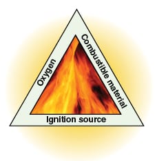
Dust explosions occur when three conditions are present simultaneously. The first is that there is a dust cloud of a combustible material (the fuel). The second is that there is sufficient quantity of oxygen. The third is that there is an ignition source of sufficient strength. When all three conditions combine, there is combustion and then an explosion if the combustion takes place in a closed environment, such as a bin, silo, dust collector or even a building.
 |
A large piece of wood, once ignited, will burn slowly, releasing its heat over a long time. But if this piece of wood is cut in small pieces, the combustion rate increases because the total contact surface area between the wood particles and the air has increased. If the wood pieces are cut up in very small pieces, such as 0.1 mm or less, and the particles form a dust cloud so that each particle has sufficiently large volume of air giving enough space for its unrestricted burning, the combustion rate will be very fast. If such an explosive combustion of dust takes place inside process equipment or work rooms, the pressure in the fully or partly enclosed space may rise rapidly and the process equipment or building may burst open. Figure 1 is called a combustion triangle because it has these three legs. It shows that a dust explosion can be prevented by eliminating any one of these three conditions.
Within the above three conditions, there is one more condition to consider. It is the concentration of dust particles in a dust cloud. For a dust explosion to take place, dust particles must be present in sufficient quantities in the closed gas space. The minimum quantity or concentration is called the lower explosive concentration (LEC). (This term is synonymous with the term lower explosive limit, or LEL, that is used for combustible gases). In addition to LEC, there is also an upper explosive concentration (UEC) and an optimum explosive concentration (OEC). At or above UEC, dust particles are so close to each other that they can burn but cannot cause a dust explosion. At the OEC, the severity of a dust explosion is at the maximum.
Dust explosions occur because this combustion takes place in a closed air space. During a dust explosion, dust particles burn and turn into vapor, which expands and burns other particles. The gaseous products of combustion cannot vent out from the space, thereby resulting in an increase in internal pressure. This increase in pressure results in bursting of the container in which combustion is taking place. In the closed vessel, pressure rises during an explosion because of the expanding vapor. The maximum pressure (Pmax) that is developed depends upon a dust property called the explosivity index (Kst). Each dust has its own Kst value. The higher the Kst, the higher the explosivity — and the higher the pressure that is generated. Values of Kst and Pmax are found by a standardized laboratory test.
A combustible dust cloud will not start to burn unless it is ignited by a source of heat of sufficient strength. The most common ignition sources are smoldering or burning materials; open flames such as from welding, cutting, matches and so on; hot surfaces such as hot bearings, dryers, heaters, compressors and so on; heat from mechanical impacts; and electrical discharges, arcs and electrostatic discharges.
A combustible dust must first be ignited before it can initiate a dust explosion. The source of ignition must have a minimum ignition energy (MIE). This is the energy that is required to initiate ignition of a dust particle. The lower the MIE, the higher the combustibility of the dust. An MIE of less than 10 mJ is considered a low MIE.
Materials that can give dust explosions are natural organic materials, such as grains, cottons, linens and sugar; synthetic organic materials, such as plastics, pigments and pesticides; coal and peat; and most metals such as aluminum, magnesium and zinc.
Defining explosivity
A number of parameters define the explosive characteristics of combustible solids.
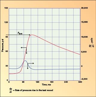
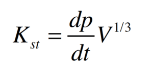
Explosivity indices (Pmax and Kst). The explosivity of dusts is measured in terms of two deflagration indices, namely the maximum deflagration pressure (Pmax) and the normalized maximum rate of pressure rise (Kst). These indices are measured in a closed, spherical test vessel (Figure 2). Pmax is the maximum pressure developed in a standardized test vessel during a dust explosion. Kst measures the severity of a dust explosion. It is related to the rate of pressure rise due to a dust explosion in a standardized test vessel. The higher the value of Kst, the greater the severity of the dust explosion. Kst is defined by Equation (1) in bars-m/s:
 |
| Figure 2. In typical tests results, Pmax is the top peak of the red line, while the maximum rate of pressure rise (dp/dt) is used with Equation (1) to determine Kst |
 (1)
(1)
Where:
p = Pressure in the test vessel, bar
t = Time, s
V = Volume of the test vessel, m3
![]() = Rate of pressure rise in the test vessel
= Rate of pressure rise in the test vessel
Heat of combustion. The heat of combustion of the material is an important parameter because it determines the amount of heat that is liberated in the explosion. Heat is liberated due to oxidation of the material. Metals such as aluminum and magnesium have much higher heat generation than organic dusts and coal. The result is that the temperatures of flames of metallic dusts such as aluminum and magnesium are very high compared with those of flames of organic dusts.
Particle size and particle size distribution (PSD). Explosiveness of a dust depends upon the particle size. In general, particles larger than about 400 microns or about 35 mesh, can burn, but not explode. Particles larger than 120 mesh can burn and explode, but the severity of the dust explosion is not very high. Particles smaller than 200 mesh are most explosive and are used to determine the dust’s explosive properties such as its Kst, MIE and LEC values.
As the particle size of a sub-200 mesh dust decreases, dust becomes more and more explosive for the following reasons:
• Its MIE decreases
• Its Pmax and Kst increase
Hybrid mixtures are mixtures of combustible gases, oxygen and combustible dusts. Hybrid mixtures are much more explosive than mixtures of combustible dusts and oxygen.
Dust classes. NFPA (National Fire Protection Association) classifications for various dusts are Class 1, Class 2 and Class 3. Class 1 is the least explosive dust, and Class 3 is the most explosive dust. Examples of these three classes of dusts are as follows:
• Class 1 dusts ( Kst = 1–200 bar-m/s): Coal, flour, starch, sugar, grain, powdered milk, polyethylene, polypropylene, epoxy resin and sulfur
• Class 2 dusts ( Kst = 201–300 bar-m/s): Organic pigment, wood, cellulose and cork
• Class 3 dusts ( Kst > 300 bar-m/s): Aluminum, magnesium and calcium
Explosion protection and prevention
If the data on the material being handled show that its dust is explosive, steps must be taken to prevent a dust explosion. These steps are given below.
Precautionary methods
Implement proper housekeeping procedures to minimize formation of a dust cloud anywhere in the building or inside process equipment. Meanwhile, minimize the probability of having a source of ignition by adopting safe housekeeping procedures and proper electrical classification. These two methods are described in more detail below.
1. Control dust emissions and accumulation.
Good housekeeping should be maintained at all times in buildings and other confined spaces to keep them free from dust concentrations. Good housekeeping is essential to prevent accumulation of dusts inside buildings or in structures, because these accumulations can result in secondary dust explosions.
Dust should not be allowed to accumulate in layers on equipment, building walls, floors or structural members. Install building venting and dust collection if good housekeeping cannot be maintained. The preferred method for dust removal is by means of properly designed vacuum-cleaning equipment. Dispersion of the dust, which results in formation of a dust cloud, must be prevented.
Meanwhile, keep the following best practices in mind:
• Dust tight process: All process components must be dust tight
• Dust collection: For process components that cannot be made dust tight, vent hoods and dust collectors must be installed to remove and collect emitted dust
• Pneumatic-conveying system design: All equipment and piping must be of dust-tight design to avoid emission of dust. Piping must be designed to withstand the maximum explosion pressure without exceeding two-thirds of the burst pressure. In case of a filter element failure, blower outlets and dust-collector outlets are located outside closed buildings to prevent formation of a dust cloud inside a building or a structure.
2. Control ignition sources.
Equipment design and arrangement, good maintenance and good housekeeping are all necessary to minimize the potential for ignition of dusts by electrical equipment or other equipment that might have high surface temperatures.
In the U.S., all electrical installations and equipment designs should meet the requirements prescribed in the U.S. National Electrical Code. This code classifies processing or manufacturing areas involving combustible materials according to class, group and division.
• Class refers to broad categories of combustible materials, where Class I includes all combustible vapors and gases, and Class II includes all combustible dusts
• Group further defines the classes based on the ease of ignition or the rate of combustion of the combustible material
• Division specifies the time periods, frequency and length, during which the combustible material is present
• Unclassified areas are areas that contain no significant amount of combustible material at any time. Electrical equipment installed in unclassified areas should meet certain minimum standards to maintain operability and prevent personnel hazards
Once it has been determined that a particular area may contain combustible materials, it is necessary to classify the area according to Division and Group.
• Division 1 locations are defined as those where flammable or combustible mixtures are normally present in sufficient quantities to present a hazard
• Division 2 locations are those where flammable or combustible mixtures are not normally present, but might be present as the result of infrequent malfunctioning of equipment
Based on the physical characteristics of the materials handled, flammable vapors or gases are assigned to Groups A, B, C or D, and combustible dusts are assigned to Groups E or G.
Bonding and grounding: Energy levels far greater than 15 mJ, easily sufficient to ignite some dusts, are obtainable via spark discharges from ungrounded conductors. To dissipate static electricity, adequate bonding and grounding must be provided for solids handling equipment and components, including conveying, feeding, blending and storage systems. Bonding is the process of electrically connecting conductive components together so that these are at the same electrical potential, and no sparks can occur between them. Equipment such as a baghouse can be comprised of a number of individual components: bag cages, bag clamps, bag grounding wire and so on. In such cases, it is important that each of the components is properly grounded and integrity of the grounding system is routinely checked. Resistance to ground shall be measured and documented for each major component.
Equipment skin-temperature limitations: In addition to establishing a number of other design and installation requirements, the skin (outside surface) temperature of any equipment should not exceed 80% of the auto ignition temperature (AIT) for the dust being used.
Maintenance: Maintenance must be provided to assure the integrity of dust-tight electrical equipment. Periodic inspection is required to detect and remove buildup of combustible dusts inside the electrical equipment.
Design methods
When handling explosive dusts, the following standards are used to design the dust-explosion prevention or protection systems:
• NFPA 68: Explosion venting
• NFPA 69: Explosion prevention
• NFPA 497M: Electrical classification of gases, vapors and dusts for electrical equipment in hazardous (classified) locations
• NFPA 650: Pneumatic conveying systems for handling of combustible materials
• NFPA 654: Fire and explosion prevention in chemical, dye, pharmaceutical and plastics industries
The use of these standards is described below in more detail.
Explosion suppression systems. Explosion suppression systems prevent high explosive pressures from developing in vessels by suppressing an explosion from starting at its source. These systems consist of a detector system that senses the start of an explosion, a pressurized container with an extinguishing medium, and a fast-opening valve that is activated by a pressure sensor through a control-monitoring unit. The extinguishing medium is dispersed into the protected vessel in a very short time in order to reduce the expected maximum pressure to a substantially lower level. The detectors that trigger the explosion-suppression system are able to start the suppression system rapidly. There are three different types of sensors: thermoelectric, optical and pressure. Pressure sensors are used more widely. The containers of the extinguishing medium are equipped with fast-acting valves, which open fully within milliseconds after the activation signal is given. The valves are designed to uniformly distribute the whole contents of the extinguishing medium within a very short time.
To prevent flashback from occurring, a positive method of isolating the explosion is required. For this isolation, devices such as mechanical decouplers, or fast-acting shut-off valves are used to isolate the vessel.
The explosion-suppression method is cost prohibitive for large equipment and vessels, such as bins and silos. It also requires diligent upkeep of the control systems so that timely operation of the valves is not affected.
Explosion pressure containment. Explosion pressure containment is a technique to protect small-sized equipment by designing it to withstand the internal pressure that is generated by an explosion. This technique is cost prohibitive for large vessels such as bins and silos.
Vessels designed for explosion pressure containment are to be designed and constructed according to the ASME Pressure Vessel Code.
The design pressure of the vessel is based on either the ultimate strength of the vessel or on the yield strength of the vessel.
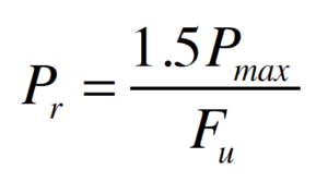
The vessel is designed so that the peak explosion pressure is less than two thirds of the vessel burst pressure. Vessel design pressure is calculated by using the method given in NFPA 69:
 (2)
(2)
Where:
Fu = Ratio of ultimate stress divided by the stress generated at the design pressure
Pr = Vessel design pressure to prevent vessel rupture, psig
Pmax = Maximum deflagration pressure, psig
Note: If it is desired that the vessel not be damaged as a result of the explosion, then Fy (the ratio of the yield stress divided by the stress at the design pressure) should be substituted for the ultimate stress in the above equation. Yield stress is the stress at which that the material deforms permanently; ultimate tensile stress is the stress at which it breaks.
Inerting. This design method is used to prevent dust explosions by reducing the oxygen concentration to less than that needed to support an explosion. It is the preferred design method for ignition-sensitive dusts. Ignition sensitive dusts are those whose sub-200-mesh fraction has an MIE less than 10 mJ. It is also used for hybrid dusts (dusts containing combustible gases).
When sufficient inert gas (typically nitrogen) is introduced, the volumetric concentration of oxygen is reduced to such a level that no ignition of the dust, combustible-gas and air mixture can occur. The inert gas must not be contaminated by air or hydrocarbons.
A minimum safety factor of 2-vol.% should be provided below the limiting oxygen concentration (LOC) if either of the following are true:
• Oxygen-limiting control equipment, analyzers and interlocks are installed to take positive action to prevent formation of an explosive mixture in the event of a failure (with a pre-alarm and a shutdown alarm)
• Or, if interlocks are not installed, alarms should be provided, and operating procedures should be in place to prevent formation of a mixture exceeding the maximum oxygen concentration above which deflagration can take place
If oxygen analyzers and alarms are not used, the maximum oxygen concentration shall be maintained at no more than 60% of the LOC, alarms must be provided on loss of the inert gas flow or pressure, and the oxygen concentration must be checked on a regularly scheduled basis. The integrity and consistency of all inerting facilities must be established by periodic checking of the oxygen concentration. Low-flow alarms should be used if procedures cannot be relied upon to ensure that the inert gas is turned on.
For those operations relying entirely on control of oxidant as the means of explosion protection (for instance, no explosion venting or other methods for explosion protection are provided), the percent O2 and inert-gas flow systems should be considered as critical controls.
Maximum oxygen concentrations for typical dusts can be found in NFPA 69.
Dust explosion venting method. This method is used to prevent catastrophic damage to equipment and facilities by properly venting a dust explosion to the outside atmosphere. It assumes that oxygen, a combustible mixture and a sufficiently strong ignition source are present so that a dust explosion can occur. Catastrophic vessel failure is prevented by providing rupture panels on vessels for pressure relief and for discharge of the explosive material, and by designing rupture panels so that the peak explosion pressure is less than two thirds of the vessel burst pressure.
The rupture panels are also called vents. Vents are openings in a vessel through which combustion-generated gases can expand and flow out. These vents serve to limit the deflagration pressure so that damage to the enclosure is limited to an acceptable level or is eliminated entirely. The area of the vents must be large enough to limit the explosion pressure to a safe level. Vents are designed so that they rupture and blow out, thus reducing the pressure inside the vessel to a level that is below the rupture-pressure rating of the vessel.
The rate of pressure rise is an important parameter in the venting of an explosion. It determines the time that is available for the products of combustion to escape from the enclosure and for the pressure to dissipate. The higher this rate, the greater the venting area that is required.
The vessel or equipment must be designed to withstand the maximum pressure attained during the venting process without catastrophic failure. Some yielding of the vessel or equipment is acceptable during a vented deflagration. For example, partial failure of the roof-to-shell seam of a vessel is not considered catastrophic failure.
Maximum pressure during venting ( Pred) should not exceed two thirds of the static burst pressure of the protected equipment. If Pred exceeds 10 psig, an ASME Code vessel is required.
The vent opening pressure ( Pstat) should be set as low as practical to minimize the rise in internal vessel pressure before the explosion is vented. This reduces the potential for damage, and for a given vent size, will result in a lower maximum pressure during venting. However, Pstat must be high enough to prevent premature opening of the vent by the combination of normal vessel-operating pressures and wind loads.
The following method for calculating required venting area ( Av, m2) is given in NFPA 68 and here in Equation (3):
 (3)
(3)
Where:
Av = Required venting area, m2
a = 5.71 X 10⁻⁴ exp(2 Pstat)
b = 0.978 exp (–0.105 Pstat)
c = –0.687 exp (0.0226 Pstat)
V = Empty vessel volume, m3
Kst = Dust deflagration index, bar-m/s
Pred = The reduced pressure (the maximum pressure actually developed in the vessel during a vented explosion), barg. The maximum pressure developed during a vented deflagration (Pred) should not exceed 2/3 burst of the vessel burst pressure.
Pstat = Pressure at which the relief device opens, barg. This is the pressure at which the vent is expected to open. It should be at least 0.5 psi greater than the peak operating pressure of the equipment. The minimum Pstat used in the venting equations is 0.1 barg (1.45 psig).
The following best practices should be observed for vents:
• Vents should be designed to give a free, unobstructed opening during a deflagration
• Access of personnel to areas that could be exposed to fireballs coming out from the deflagration vents should be restricted unless deflector shields are provided. Shields should not interfere with the venting process
• Panels shall be adequately tethered by using chains or cables, where practical, to prevent them from becoming missiles during the venting process
• Vent panels should be located so that they are not obstructed by the solids’ level in the vessel. For example, by ensuring that the vent panel bottoms are at least 1 ft higher than the maximum solids level
• Where side vent panels are used, they should be symmetrically arranged around the perimeter of the vented vessel
• All equipment using explosion relief panels should be located outside of closed structures or buildings. If this is not possible and the equipment volume exceeds 8 ft3, the equipment is to be vented to the outside through a properly designed duct
• Vent panels should be manufactured by vendors who have special expertise in their design and testing
• Vents can fail by rupture (for instance, metal fails in tension), or they can fail by blowing out from their frames or by failure of their fasteners. When fasteners are used, avoid spring-loaded latching devices because they are not reliable
Buildings. Buildings that have properly designed and maintained dust handling and process equipment do not require explosion venting. However, damage-limiting construction of the building is desirable. In locations where environmental dust-concentration conditions exist, such as due to poor maintenance and housekeeping, building explosion venting should be provided, as given in NFPA 68.
Dust collectors and bag houses. Dust collectors and bag houses pose significant dust explosion hazards because they inherently have a dusty internal environment. Their tube sheets and bag cages must be properly bonded and grounded to prevent ignition caused by static charges. Properly designed explosion vents should be provided on the dusty side of the dust collector. Dust collectors should be located outside of buildings or located close to external walls. When installed above bins and silos as bin vent filters, use a rotary valve to prevent propagation of a dust explosion into the bin or silo. When handling low-MIE dusts use the inerting method, as described previously, instead of explosion vents.
Author

Amrit Agarwal is a consulting engineer with Pneumatic Conveying Consulting (7 Carriage Road, Charleston, WV, 25314; Phone: 304-553-1350, Email: polypcc@aol.com). He started his consulting work after retiring from The Dow Chemical Co. in 2002 as a senior research specialist. He has more than 47 years of design and operating experience in bulk solids handling and pneumatic conveying. He holds an M.S. in mechanical engineering from the University of Wisconsin-Madison, and an M.B.A. from the West Virginia College of Graduate Studies in Charleston.