A new correlation that matches most commercial trays
The sieve tray has been in the distillation market place for many decades. It has been used extensively in distillation columns worldwide as a highly efficient vapor-liquid-contacting device. Many people have examined dry tray pressure-drop data for sieve tray decks and there have been several attempts to correlate these data. But the error of such correlations is high.
 |
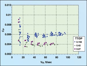
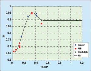
| Figure 1. A plot of sieve tray orifice coefficient at 12% open area and high Reynolds Number for three sources |
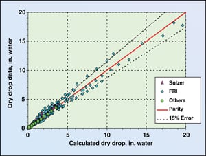 |
| Figure 2. Parity plot of accumulated data versus the correlation of Stichlmair & Mersmann |
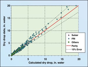 |
| Figure 3. Parity plot of accumulated data versus the correlation of Liebson and others |
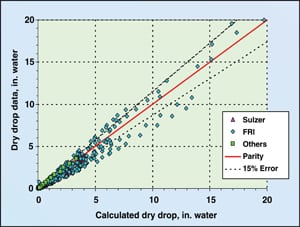 |
| Figure 4. Parity plot of accumulated data versus the correlation of Kolodzie and Van Winkle |
 |
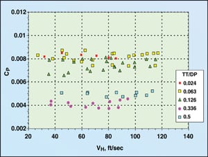
| Figure 5. Sulzer dry tray pressure drop data |
 |
| Figure 6. FRI dry tray pressure drop data |
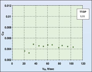 |
| Figure 7. Biddulph dry tray pressure drop data |
This article — a supplement to the author’s earlier article on the dry tray pressure drop of movable and fixed valves [1] — presents a new correlation for sieve tray pressure drop that incorporates tray thickness, hole diameter and open area, and is compared to data. The improved equation matches — within a 15% accuracy — experimental data from three different sources, and can be used for most commercial sieve-tray applications. Limitations on this new equation are also discussed.
Existing methods
Dry tray pressure drop is an extremely important hydraulic parameter that aids the tray designer in many different ways. Obviously, it is one of the major contributing parameters in the overall tray pressure drop. But more importantly, its magnitude can tell an experienced designer whether he or she is near flood, is at turndown, has a stable tray or may be approaching spray fluidization. Finally, it can be used to understand the overall behavior and performance of a tray. Dry tray pressure drop is a fundamental building block of most other hydraulic parameters, and its accuracy (or inaccuracy) has far reaching consequences.
The hydraulic parameter is quite a simple concept. For fixed opening devices, the dry tray pressure drop can be reduced from Bernoulli’s principles taking on the form of the following equation:
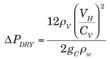
(1)
Where,
∆PDRY = Dry tray pressure drop, in. of water
VH = Hole velocity, ft/sec
ρV = Vapor density, lb/ft 3
CV = Hole (orifice) coefficient
ρw = Water density = 62.428 lb/ft 3
gC = Acceleration of gravity = 32.174 ft/s2
If one combines all the constants from Equation (1) into a single constant Cp, the equation becomes very simple:
![]() (2)
(2)
Where,
![]()
(3)
Even though Equation (2) appears to be quite simple, the orifice coefficient is, in reality, quite complex. Many people have attempted to determine a correlation for the orifice coefficient but all appear to have deficiencies in accurately determining this value for the full range of opening sizes, tray thicknesses and hole pitch. Lockett [2] notes that there are over 20 correlations available in the literature for the determination of the orifice coefficient. Kolodzie and Van Winkle [3] as well as Smith and Van Winkle [4] have performed extensive work and defined a very detailed orifice coefficient for sieve tray devices. These two sources indicate that there is also a hole Reynolds number effect. Stichlmair and Mersmann [5] also considered the Reynolds number in their correlation. Liebson and others [6], however, ignored the Reynolds number and determined a function of the orifice coefficient that utilizes simply the opening size, tray thickness (TT) and hole pitch.
Figure 1 shows the difference between the above-mentioned three sources. One can see that all three show a higher CV at increased deck thickness to hole diameter (DP) ratios. However, only Stichlmair and Kolodzie indicate that there appears to be two discrete orifice coefficient values with a transition region between.
Lockett indicates that previous authors argue the vena-contracta of the vapor leaving thin trays is well above the tray deck. As a result, there is a pressure drop associated with the vapor circulating back in the bulk vapor above the tray. For thicker trays, the vena-contracta lies within the hole itself and as a result, the back-circulation of vapor is reduced.
Sieve tray, dry-pressure-drop data were obtained from several sources. These would include laboratory data from the author’s employer [7] and dry tray pressure drop data from Fractionation Research, Inc. (FRI) [8]. In addition, Biddulph and Thomas [ 9] plotted several data points for a deck thickness to hole diameter ratio of 1.11.
A comparison of these data to the predicted values from Stichlmair and Mersmann is shown via parity plot in Figure 2. A comparison of these data to the predicted values from Liebson and others is shown in Figure 3. A comparison of these data to the predicted values from Kolodzie and van Winkle is shown in Figure 4. In all three cases there is considerable data that lie outside the 15% error band, especially at low pressure drop values. The standard deviation of the Kolodzie and van Winkle data is over 26%.
An examination of the dry tray pressure drop data showed that the orifice coefficient CP had a constant value over the bulk of vapor velocities ( VH) through the experimental orifice plates. Figures 5 through 7 show these constant values for the Sulzer, FRI and Biddulph data, respectively.
The constant values shown in Figures 5 through 7 are then plotted in Figure 8 to show a relationship between the orifice coefficient CP and tray thickness divided by hole diameter. After converting CP into CV, Figure 9 was generated.
The Kolodzie and Van Winkle relationship was used as a basis to establish a new correlation. Their work seemed to encompass the largest combination of open area, tray thicknesses and hole diameters.
Kolodzie and Van Winkle used a term K to represent the effect of open area, namely hole diameter over hole pitch. Pitch is the distance between adjacent hole centers in a triangular pattern. This relationship is shown in Equation (4).
![]()
(4)
Improved method
In this new method, K was then plotted in Figure 10 and a
curve was generated to best fit these data.
The least squares curve fit is shown in Equation (5).
![]()
(5)
 |
| Figure 8. The relationship between the orifice coefficient and tray thickness |
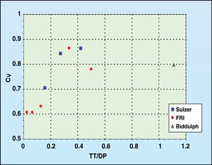 |
| Figure 9. The data of Figure 8 after converting CP into CV |
 |
| Figure 10. The best fit of the data to the K equation of Kolodzie and Van Winkle |
 |
| Figure 11. The improved Kolodzie and Van Winkle correlation presented in this article |
 |
| Figure 12. Final results from the improved correlation |
Limitations and exceptions
There are, however, some limitations on this K equation. For any value of thickness/hole diameter less than 0.04, the value of K should equal 0.66. For any value of thickness/hole diameter greater than 0.52, the value of K should equal 0.894. In addition this equation is only good for hole Reynolds numbers greater than 4,000. For most applications this will be true. Keep in mind however that when the hole Reynolds number is low, the dry tray pressure drop is also very low and the accuracy of its value becomes insignificant in comparison to the total tray pressure drop.
Please note that in the improved K equation, when the thickness to hole diameter ratio exceeds values of 0.5 the equation is highly dependent on the single point from Biddulph [9]. Additional data from commercial sieve trays with tray thickness to hole diameter ratios above 0.5 are needed to refine this correlation further. Typically however, there are few commercial applications where the thickness to hole diameter ratio exceeds 0.5. The closest application would be where ¼ in. holes are placed on 10 gage (0.1345-in. thick) tray decks, which is rare. Therefore, this equation can be used with confidence in most commercial sieve tray applications.
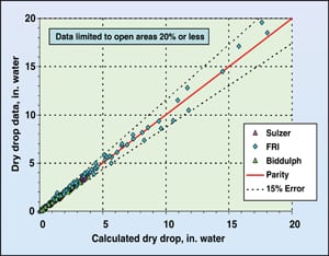
Figure 11 was generated by applying the improved K equation to the above mentioned data, but limiting those data to open areas that are 20% of the active area or less. This figure clearly shows that the improved correlation is superior to the original Kolodzie and Van Winkle curve shown in Figure 4.
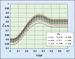
The standard deviation of the data here is 13.1%. This has been cut in half from the original correlation. Finally, the orifice coefficient CV is generated for the most commonly applied tray thicknesses, hole diameters and fraction open area (FP) and shown in Figure 12.
Edited by Gerald Ondrey
References
|
Author
|
 Daniel R. Summers is the Tray Technology manager for Sulzer Chemtech, USA at its Tulsa, Oklahoma facility (Sulzer Chemtech USA, Inc., 4019 S. Jackson Avenue, 74107 Tulsa, OK, 74107; Phone: 918-447-7654; Fax: 918-446-5321; Email: