Today’s detection equipment can provide early sensing of H2 gas and flames, provide alarm information to a fire- and gas-safety system controller to initiate mitigating measures, and integrate with process control to further minimize H2-fire risk
Hydrogen is the most flammable element on earth [1]. However, this colorless, odorless and tasteless substance rarely exists in its pure form. Instead, it normally combines with other elements, in water molecules, for example, or in industrial compounds. However, H2 is widely used in the chemical process industries (CPI, Figure 1). For example, in the chemical industry, it is an important component in the production of polymers and ammonia for fertilizers. In petroleum refining, it is used in the reforming process for producing high-grade gasoline, as well as in removing sulfur compounds from petroleum so they will not poison vehicle catalytic converters [2].
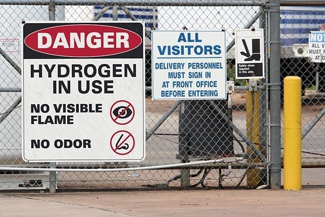
Figure 1. Hydrogen is widely used throughout the chemical process industries
According to the U.S. Dept. of Energy’s Office of Energy Efficiency & Renewable Energy (www.energy.gov/eere), 10 million metric tons of H2 are produced in the U.S. annually [3]. While playing an indispensable role in many processes, H2 also poses a unique and potentially significant threat to chemical processing facilities. The dangers to personnel and property, however, can be minimized by choosing the right equipment to detect and respond to hydrogen-related hazards.
Challenges with H 2
The challenge with using H2 in CPI plants and other industrial settings is that this nontoxic and seemingly harmless gas has highly reactive and explosive properties. In fact, the National Fire Protection Association (NFPA; Quincy, Mass.; www.nfpa.org) — the main fire codes and standards organization in the U.S. — gives H2 its highest rating of “4” on the flammability scale (Figure 2), because H2 is flammable when mixed with other elements, even in small amounts with ordinary air [4].
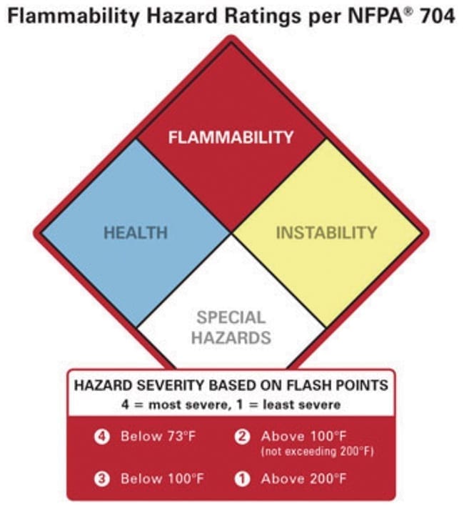
Figure 2. Materials rated a “4” in terms of flammability in NFPA 704 are those that will readily burn at room temperature, including acetylene, propane and hydrogen gas
In addition, it only takes a small amount of energy to ignite H2. The gas can even self-ignite without energy from an external source when it is leaking from a pipe at high pressure.
Making matters more challenging for plant personnel and unlike a hydrocarbon flame, a H2 flame cannot be easily detected by human senses (Figure 3). Workers approaching a H2 flame may not see it, even up close. Instead, they may see a shimmering, mirage-like area or possibly sparks, which are actually dust particles burning briefly in the flame.
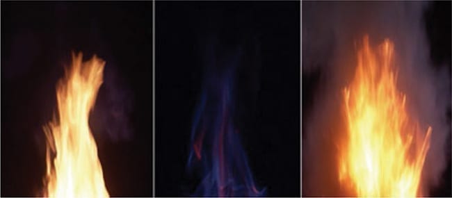
Figure 3. Every combustible gas burns differently, producing a signature flame. Compared to hydrocarbon flames, depicted on the right and left, a hydrogen flame (center) emits little visible light and infrared radiant heat, and is therefore more difficult to detect
Adding to the danger, personnel approaching a H2 flame will not feel intense heat. This is because H2 flames typically emit less of the infrared (IR) radiation that causes humans to sense heat when near a flame than hydrocarbon fires.
With little or nothing to see and a small amount of radiant heat to be felt, human senses may not warn people to stop as they approach a H2 flame, potentially allowing them to unknowingly walk right into it.
First line of defense
For the reasons just mentioned, chemical plants that use H2 need fire and gas (F&G) safety systems with flame and gas-leak detection technologies in order to minimize fire-related risks to personnel and processes. The first line of defense against H2-related dangers is gas detection equipment. Though people cannot see, smell or taste H2 gas under normal conditions, gas detection equipment can sense a leak before it ignites, increasing the possibility of stopping a leak before it causes a fire or explosion.
Two common technologies for detecting combustible gases are IR and catalytic bead (Pellistor) detectors. Today’s IR-based combustible-gas detectors cannot detect H2. This makes catalytic bead-type detectors the appropriate technology choice between the two for detecting H2 in combustible concentrations.
A catalytic bead sensor detects a combustible gas that combines with oxygen to produce heat. This sensor usually consists of a matched pair of platinum wire-wound resistors, one of which is encased in a ceramic bead. The active catalytic bead is coated with a catalyst, while the reference catalytic bead remains untreated. The resistors are then enclosed behind a flame-proof sinter or porous filter.
When a combustible gas comes in contact with the active catalytic bead surface, the gas is oxidized and heat is released, which changes the resistance of the wire. The reference (or passive) bead maintains the same electrical resistance in clean air as the active bead, but does not catalyze combustible gas. Combustible gas concentrations are then determined by comparing the difference between the active and passive bead circuits.
On the downside, catalytic bead detectors may not have the ability to signal a fault when they fail. They are also susceptible to poisoning, which can cause them to fail when exposed to silicones and other common chemicals in industrial environments. In these cases, the porous filter clogs, causing the active bead to behave in the same manner as the reference bead. If the active bead in a catalytic detector cannot sense gas, plant personnel have no way of knowing. Therefore, periodic bump or proof testing with calibration gas is required to ensure proper sensor operation.
Plant personnel or others placing catalytic bead-type gas detectors should keep in mind that light H2 gas quickly floats upward and disperses. Therefore, detectors should be located close to and above spots where a leak might occur — just above a valve, for example.
Flame detection options
If a H2 leak does ignite, F&G safety systems include detectors that can quickly sense a H2 flame. One option for H2-flame detection is a thermal heat detector, which will not sound an alarm until the temperature of the monitored area exceeds the detector’s alarm set point. For best results, these detectors should be placed directly above the sites of a potential H2 flame.
Even in this position, the source of a H2 leak may produce a flame directed away from the detector, delaying the response time. Another concern for users of thermal detectors is that a H2 flame’s low IR radiation may not be enough to trigger an alarm.
An alternative to thermal detection is an optical detector that can “see” a hydrogen flame. Compared to hydrocarbon flames, however, hydrogen flames emit little visible light or IR radiant heat. One potential option is to use an optical detector that senses the ultraviolet (UV) radiation emitted by hydrogen flames.
UV flame detectors use anode/cathode Geiger-Mueller-type vacuum tubes to sense UV radiation. When this radiation enters the vacuum tube and strikes the cathode, energy from the UV photon releases a photoelectron and creates an electrical impulse as it travels to the anode. UV flame detectors excel at fast detection of H2 flames.
On the other hand, UV flame detectors are sensitive to arcs, sparks, welding, lightning and other UV emitting non-flame sources. These sources can cause the detectors to alarm, which may result in costly production downtime.
Therefore, UV flame detectors are best suited for enclosed rooms and other locations isolated from potential sources of false alarms. Even in enclosed rooms, it may not be possible to eliminate all sources of nuisance alarms from UV sources.
Superior false-alarm rejection is one of the main reasons multi-spectrum infrared (MIR) flame detection has become the preferred choice of many operators for detecting H2 flames in most industrial settings (Figure 4). With a unique set of IR sensor filters, some MIR detectors are designed specifically to detect the IR radiation from H2 flames.
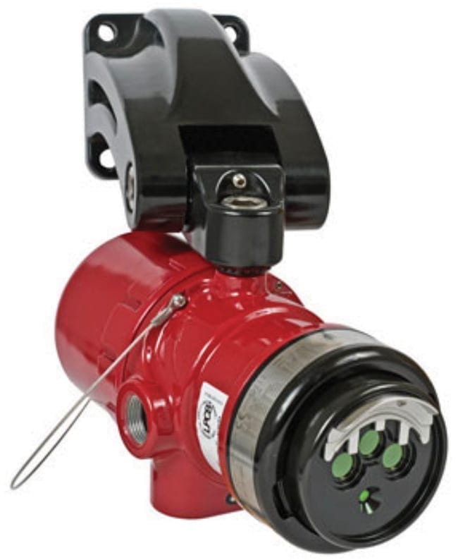
Figure 4. To “see” hydrogen flames, today’s best technology is multispectrum infrared flame detection, as used in this hydrogen flame detector
MIR flame detectors rely on a combination of IR filters and software analysis to detect flames and reduce the potential for false alarms. Unlike UV flame detectors, MIR detectors are designed not to enter an alarm condition when exposed to arcs, sparks, welding and lightning.
In H2 -detection applications, MIR detectors offer good response time and range. Equipped with an optimum IR filter set, some MIR devices can detect H2 fires at about double the range of a UV flame detector. While the range of MIR detectors can be reduced by the presence of water or ice on the lens, some detectors are equipped with lens heaters that melt ice and accelerate evaporation of water.
Brain of the system
To continuously monitor and analyze data from gas and flame detectors, F&G safety systems require controllers that provide alarm monitoring and some level of diagnostics. If a hazard is detected, the controller takes the appropriate actions based upon its pre-programmed logic. These actions often include providing alarm notification and activation of suppression systems to mitigate the hazard. In addition to handling inputs and outputs, the controller should be able to provide realtime F&G safety system status and diagnostics. It should also facilitate programming and configuration of flame and gas detectors, as well as other field devices that are part of the F&G system.
Typically, F&G safety-system controllers have been limited to being hardwired together using analog or contact closures in a conventional (that is, point-to-point) design. Though capable of providing alarm and fault information, the conventional design does not give controllers access to specific details of fire-related events because of the simple, binary nature of the communication path. In addition, this design provides only limited diagnostics, is not inherently fault-tolerant and limits configuration flexibility.
This is why today’s advanced F&G safety systems feature a redundant control and bi-directional fault-tolerant loop design. Systems of this type are safety integrity level (SIL)-2 certified and provide alarm, fault, status and enhanced diagnostic information that can be communicated with other subsystems, such as process control. The controller is in constant communication with each device in the loop, so it has the latest alarm and diagnostic information, making this configuration more reliable than point-to-point designs as well.
Control system integration
Consider a situation in which flammable materials continue to be pumped into an area of a chemical plant where fire has been detected. To prevent potentially disastrous scenarios like this, it is imperative that the plant’s F&G safety system be able to communicate with the process control system (PCS).
Any F&G system deployed in a chemical facility should be able to provide detection-device status in defined process areas to the PCS so the process owner is kept informed about events that may threaten personnel and/or operations. While this level of integration is important, the F&G system must remain independent of the PCS, so failure of the PCS will not affect vital fire-protection functions in the facility.
Performance of both of the F&G system and the PCS must be validated to ensure they are capable of reaching the defined risk-reduction target for the facility. Applicable performance requirements are contained in codes and standards. Performance information about specific equipment is provided in manufacturer documentation.
Product certification
F&G systems and equipment are covered in fire standards such as NFPA 70 (the NFPA 70 National Electrical Code) [5] and NFPA 72, the National Fire Alarm and Signaling Code [6] The surest way to know that fire-protection equipment meets safety standards, such as those in NFPA 70 and 72, is to specify equipment with certification documentation. Performance testing and certification verify that a device will operate as specified by the manufacturer under a wide range of conditions. F&G safety systems and key components, such as controllers and detectors, should be properly certified for hazardous locations, performance and functional safety.
Product testing and evaluation should be conducted pursuant to the requirements of a properly accredited third-party testing and certification agency, which provides potential users with an independent and unbiased product evaluation. A number of highly regarded independent organizations test fire-protection equipment using their own documented safety and performance criteria. Manufacturers using this evaluation approach will be able to provide proof of certification for their products.
References
- www.thoughtco.com/most-flammable-chemical-607315
- Center for Industry Education Collaboration, www.essentialchemicalindustry.org/chemicals/hydrogen.html
- Office of Energy Efficiency & Renewable Energy, www.energy.gov, www.energy.gov/eere/fuelcells/fact-month-may-2018-10-million-metric-tons-hydrogen-produced-annually-united-states
- For more information, go to www.nfpa.org.
- NFPA 704: Standard System for the Identification of the Hazards of Materials for Emergency Response, 2017; www.nfpa.org
- Chapter 17 of NFPA 72 lays out requirements for various types of devices that can be used to detect indications of fire.
Authors
 Michael J. Hosch is lead applications engineer at Det-Tronics (Minneapolis, Minnesota; Phone: 952-746-9100; Email:. [email protected]). Hosch has worked with optical flame detection for Det-Tronics for over 30 years and has developed extensive experience in the application of flame detection in high-hazard environments, ranging from the oil-and-gas industry to aircraft hangar and munitions manufacturing.
 Aaron Paterson is the Flame Product Line manager at Det-Tronics (same address as Hosch, above; Phone: 952-946-6471, Email: [email protected]). Paterson has been providing technical support to Det-Tronics customers who use flame and gas detection in challenging and unique environments since 2012. In his current role as Flame Product Line manager, Paterson is responsible for recommending product innovations and developing product roadmaps for the flame detection product line. Paterson has a bachelor’s degree in business administration from North Dakota State University.