Tracing its origins to 1915, the American Society of Mechanical Engineers (ASME) Boiler and Pressure Vessel Code (the code) [1] has become the established safety standard governing the design, fabrication and inspection of boilers and pressure vessels, as well as nuclear power plant components during construction. Section VIII, Division I of the code addresses pressure vessels operating at either internal or external pressures exceeding 15 psig.
Despite the prevalence of pressure vessels in the chemical process industries (CPI), a clear understanding of the basis-of-design responsibilities involved in designing, fabricating and repairing such a device remains elusive. Vessel users are responsible for providing all necessary data to ensure the manufacturer can design and fabricate a pressure vessel in full compliance with the code.

The lack of clear understanding can result in a disconnect between users and manufacturers during pressure vessel specification. The disconnect is often magnified because, although Section U-2(a) of the ASME Code clearly defines the responsibilities for establishing the basis of design, users often lack access to the code language and its associated interpretations. Basis of design refers to well-defined information that could form the foundation for inspection and test acceptance criteria.
While engineering specifications often provide sufficient data for a manufacturer in certain basic areas — such as internal and external pressure, temperature, vessel orientation, material of construction, corrosion allowance and vessel contents — pressure vessel fabricators usually receive insufficient information from users in areas such as wind, seismic and external loadings. The incomplete specification information makes a proper and complete vessel design difficult and can lead to inaccurate price quotes. Providing complete information will help avoid cost overruns and change-orders.
The intent of this article is to clarify those areas of pressure vessel specification where information is commonly omitted and areas where further clarification is required. Further, this article is intended to improve understanding of which responsibilities are shouldered by vessel users and which by manufacturers. By providing a more comprehensive basis of design for a vessel, users and manufacturers can save money and formulate specifications with public safety in mind.
All 50 U.S. states, all Canadian provinces and many local jurisdictions and territories have formally adopted the ASME Code as a safety standard for boilers and pressure vessels. Each jurisdiction employs a chief inspector who is a member of the National Board of Boiler and Pressure Vessel Inspectors. Meanwhile, the code is frequently a prevailing basis in other countries throughout the world.
Vessel Design
Design versus operating T and P
In engineering specifications, often no distinction is made between the design pressure and operating pressure. Section UG-21 of the code recommends a suitable design pressure above the operating pressure of the vessel at which the vessel will normally operate. The operating pressure should represent the most severe exposure of pressure and temperature the vessel is expected to experience under normal operating conditions, whereas the design pressure should allow for potential pressure surges up to the setting of the pressure-relief device. The design temperature should account for the lowest and highest operating temperature, in addition to operational upsets, atmospheric temperature and other sources of cooling. The design and operating conditions should be established in a process safety review meeting within the user’s organization.
Based upon the material of construction, the nominal plate thickness and the minimum design temperature, the manufacturer will have to determine the requirements for welding. For carbon steel and low-alloy vessels, the requirement for Charpy impact testing can be determined in Section UCS-66 of the code. For high-alloy vessels, such as those fabricated of austenitic stainless steel, the manufacturer will refer to Section UHA-51 of the code. The manufacturer will determine if impact testing is required and if the shop has a qualified weld procedure to meet the requirements of the Code.
 |
|
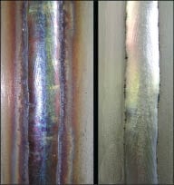
Figure 1. The pickling process removes
the heat tint produced during welding (left = before; right = after) |
Vessel contents
With regard to vessel contents, the key phrase for the fabricator is “lethal service.” Vessels are considered lethal service if the contents, whether mixed with air or alone, are dangerous to life when inhaled. Lethal service imposes mandatory Code-compliance requirements on the manufacturer, such as 100% radiography of all welds. These requirements can substantially increase the vessel’s fabrication cost.
If the process involves hydrogen sulfide, where there is a risk of sulfide stress cracking, then the manufacturer needs to be advised of the requirements of the National Association of Corrosion Engineers (NACE) standard RP0472 and NACE publication 8X194. Hydrogen sulfide service will have restrictions for material-grade, post-weld heat treatment, and allowable hardness of the weld and heat-affected zone; all of which will impact the manufacturer’s cost for fabrication. The user should identify dangerous compounds in its process and address the dangers in a process safety review meeting.
The user should provide the specific gravity of the process fluid, since the manufacturer must account for the additional static pressure due to the static head of the liquid, per section UG-22(b).
Materials of construction
While the material of construction is commonly included in equipment specifications, clarification is often required as to the impact the material specification has on the fabrication and the quote. Information in the specification should allow the manufacturer to determine whether or not its qualified weld procedures and qualified welders are sufficient for the alloy specified. In cases where the manufacturer has to qualify a procedure for an alloy not commonly welded in the shop, the cost impact should be evaluated.
The material specification and the grade designation should also be provided to the manufacturer. For example, if the vessel is fabricated from austenitic stainless plate, then indicate the ASTM International (ASTM)specification and grade, such as: A240-316L. For the nozzles the specification and grade will be A312-316L. If the process safety review determines that seamless pipe is required for the nozzles, then this should be clarified, since it will impact the vessel’s cost. For flanges, the specification and grade will be A182F-316L. Depending on the process, some users may prefer using a carbon-steel backing flange in conjunction with a stainless-steel stub-end. If that is the case, clearly indicate it in the specification.
A material specification for appurtenances is commonly not given. Items such as lifting lugs, support lugs, skirts and support legs can often be specified with a different grade material than that of pressure retaining items. The user may have a vessel where all of the pressure-retaining items and wetted surfaces are 316L stainless steel, but the lifting lugs and support ring may be fabricated from 304 stainless steel. Depending on the user and the service, a stainless-steel vessel with carbon-steel legs might be acceptable, provided there is a “poison pad” between the two materials such that the pressure-retaining items are not at risk of carbon contamination. Often manufacturers will specify an alternate material grade for appurtenances in order to minimize fabrication cost. If alternate material grades are unacceptable for appurtenances, that should be stated in the specification, particularly when manufacturers are competitively bidding for the contract.
Stainless-steel surface finish
For users in the food-and-beverage and pharmaceutical industries, there are often requirements for special internal- and external-surface finishes. Ambiguity and different interpretations about user expectations and manufacturer capabilities can arise when the mechanical finish is specified as one of the following: satin, polished, bright, dull or mirror. Parameters such as contact time, material feedrate, abrasive pressure and application of lubrication will have an impact on the finished product. Special finishes supplied by the manufacturer are not published by ASTM International.
Polishing and grinding involve the removal of metal from a surface with an abrasive, resulting in surface directional marks. There is no definition of an abrasive grit size that differentiates grinding from polishing. As a guide, however, grit sizes of 80 and coarser can be associated with grinding, whereas grit sizes of 120 and finer can be associated with polishing. Nevertheless, simply specifying the grit size cannot be equated to a specific surface finish.
Buffing is not intended to remove metal from the surface. It is intended to brighten and smooth the existing surface with cotton- or felt-based media and with the application of lubricants to the buffing wheel.
For precise and consistent results, it is recommended that the surface finish be specified in a range of minimum and maximum level of roughness average (Ra). This can be expressed in microinches or micrometers (Table 1).
| Table 1. surface finish comparison | ||
| Grit finish | Ra (microinch) | RMS (µm) |
| 36 | 142 | 4.06 |
| 60 | 87 | 2.49 |
| 80 | 71 | 2.03 |
| 120 | 52 | 1.47 |
| 150 | 42 | 1.20 |
| 180 | 30 | 0.86 |
| 220 | 19 | 0.53 |
| 240 | 15 | 0.43 |
| 320 | 12 | 0.36 |
| 400 | 9 | 0.25 |
| Mirror | +/- 4 | 0.13 |
The Specialty Steel Industry of North America (SSINA) publishes a designer handbook of specialty finishes for stainless steel, which provides detailed descriptions and sample photographs. The handbook can be downloaded free of charge at http://www.ssina.com. Photographs for comparison of certain standard finishes (Nos. 1, 2B, 2D, 2BA, 3, 4, 6, 7 and 8) for sheets or various nominal thicknesses can also be found at the website.
Vessel heads
Some of the most common heads in service are as follows: ASME flanged and dished (torispherical), 2:1 elliptical flanged and dished (ellipsoidal), conical, toriconical, hemispherical and flat.
Heads are formed based upon outside vessel diameter, with the exception of elliptical and hemispherical heads, which are formed to the inside diameter. When ordering the head, the vessel manufacturer will provide the head manufacturer with the minimum permitted thickness that is required based upon the calculations. Thinning of the vessel head takes place primarily at the knuckle regions and the center of the dish (Table 2).
| Table 2. guideline for head thinning during forming | |
| Head thickness range | Allowable thinning during forming |
| 12-gauge, up to and including 0.25-in. plate | 0.032 in. |
| 5/16-in. nominal thicknesses up to and including 0.5-in. plate | 0.062 in. |
| 9/16-in nominal thickness up to and including 1.0-in. plate | 15% |
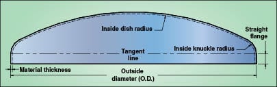
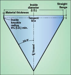
Torispherical heads. Torispherical heads have dish radii equal to the diameter of the head or vessel shell, and the knuckle is 6% of the head inside-crown radius as required by Section UG-32(e) of the ASME Code (Figure 2). The straight flange (skirt) is a standard 1.5 in. for heads formed from 3/16-in. plate and heavier. Straight flanges up to 2 in. can be provided upon request. For some head manufacturers, a 3-in. straight flange can be provided for head diameters ranging from 36 to 54 in. as long as there is a minimum plate thickness of 3/16 in. For heads 54 in. and larger, a 3-in. straight flange can be provided with a minimum plate thickness of 0.25 in.
 |
 |
 |
|
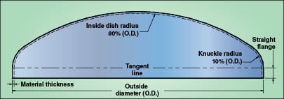
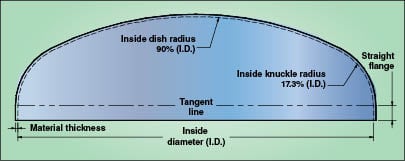
Figure 2. The geometry of an ASME 80-10 torispherical head is such that the dish radius is
80% of the head diameter and the knuckle radius is 10% of the head diameter, while an ellipsoidal head has a dish radius that is 90% of the inside head diameter and a knuckle 17.3% of the inside head diameter |
When specifying a torispherical head for a pressure vessel, it is important for the user to clearly define an ASME flanged and dished (torispherical) head. Standard flanged and dished heads are manufactured, but do not meet the code requirement of a minimum 6% inside-crown radius for the knuckle region. As a result, the standard flanged and dished heads provide a higher stress concentration factor and discontinuity in the knuckle region. Some manufacturers offer an ASME 80–10 head where the dish radius is 80% of the head diameter and the knuckle radius is 10% of the head diameter. The advantage of an ASME 80–10 head is that it is thinner (~66% of the thickness of an ASME torispherical head), which results in a smaller blank size and reduced labor cost.
A third option for a torispherical head is an ASME high-crown head, where the dish radius is 80% of the head diameter and the knuckle radius is a minimum of 6% of the head diameter.
Ellipsoidal (2:1) head. A 2:1 elliptical flanged and dished head provides a dish radius that is approximately 90% of the inside head diameter and a knuckle that is approximately 17.3% of the inside head diameter. The geometry of the ellipsoidal head is provided in Section UG-32(d) of the ASME Code.
The decision of whether to specify and use a torispherical head versus an ellipsoidal head is mainly an issue of head clearance. Users should decide which head better suits their needs.
If a dished head requires a bolting flange, then the manufacturer must design the head and flange in accordance with the code’s Appendix 1 (1–6). The cost of adding a bolting flange is significant.
Toriconical heads. The transition geometry of a toriconical head is typically limited to a maximum half-apex angle of 30 deg (Figure 3). The knuckle cannot be less than 6% of the outside diameter of the head skirt or less than three times the calculated knuckle thickness as outlined in UG-32(h).
Toriconical heads or transitions may be used when the half-apex angle is greater than 30 deg and further requires the design to be in compliance with the mandatory Appendix 1 of the code. A conical head or transition does not have a knuckle. Therefore a reinforcing ring is required by Appendix 1–5(d) and (e). Half-apex angles greater than 30 deg for conical heads and transitions shall be in accordance with Appendix 1–5(g) of the code.
 |
|
Figure 3. Toriconical heads and transition geometries
are limited to a maximum half-apex angle of 30 deg |
 |
|
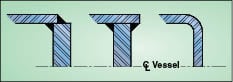
Figure 4. Requirements of un-stayed flat heads and
covers include bolted blind flanges, flat plates with retaining rings and threaded covers. Here are a few examples |
Un-stayed flat heads. These can be incorporated into the design, but have limitations in pressure and temperature due to their geometry (Figure 4). Section UG-34 of the code provides the design requirements for un-stayed flat heads and covers. This includes bolted blind flanges, flat plates with retaining rings, and threaded covers. The section provides nineteen examples of un-stayed flat heads that can be used, but clarifies that other designs, which meet the requirements of UG-34, are acceptable.
The user may have an un-stayed flat head design that is to be incorporated. If so, users should provide a sketch of what is desired and allow the manufacturer to bring the proposed design into compliance with the code.
Details are needed when specifying closure heads on a pressure vessel. When specifying the vessel shell length, reference it from the tangent line of one head to the tangent line of the opposite head. The tangent line is an accepted datum for most shops.
Nozzle schedule
Most users generally provide a nozzle schedule, but significant information is inherently omitted. When providing a nozzle schedule, the manufacturer is focused on size, type and quantity. The physical placement of the nozzles, and their projections can be addressed during the drawing review process (Figures 5 and 6). The user needs to be clear on the types of flanges required — raised-face slip-on flanges, raised-face weld-neck flanges or lap-joint flanges with stub-ends. When stub-ends are considered, be sure to clarify Type A or B stubs ends. For the nozzle necks and any internal piping, specify electric-resistance-welded (ERW) pipe or seamless pipe (SMLS). Seamless pipe cost is considerably higher and will increase the vessel’s cost. The manufacturer is responsible for determining if the nozzle requires a reinforcement pad.
Users should also define the nozzles used for inspection and overpressure protection. If there is not a safety relief device attached directly to the vessel, most users will not identify an overpressure protection nozzle. If the safety relief device is not directly attached to the vessel, identify the nozzle connected to the piping system containing the safety relief device. If the vessel has a manway opening then clarify whether or not a hinge or davit arm is required. If the vessel requires a stud pad or sight glass, then specify it.
A manufacturer and model number for the sight glass should be provided with the vessel specification so the manufacturer can obtain a quote. For stud pads, be sure to specify the size and flange rating for the pad.
 |
|
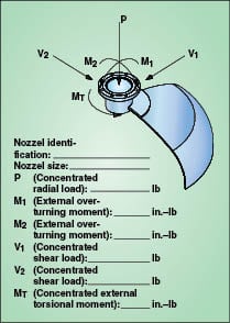
Figure 5. It is the vessel user’s responsibility to
notify the fabricator as to whether the piping imposes excessive loadings on the nozzles |
 |
|
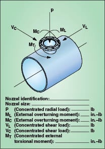
Figure 6. Agitators and mixers are sources of
external nozzle loading. Users should obtain the mixer reaction loads from their maker, and relate that to the vessel manufacturer |
Safety and testing
Corrosion allowance
The user should also specify a corrosion allowance for the vessel according to Section UG-25 of the pressure vessel code. The only situation for which a corrosion allowance is not required in the specification is when experience in “like service” has proven corrosion did not occur or the corrosion is superficial. Both the internal and external surfaces of the vessel should be considered.
If the vessel is subject to internal corrosion, then the design should incorporate a drain nozzle at the lowest point or a pipe extending into the vessel from any other location to within 0.25 in. of the lowest point.
Depending on the service, the user may elect to have telltale holes drilled part of the way into the pressure retaining items. The code requires the holes to be 1/16-in. to 3/16-in. dia. The holes’ depth must be greater than 80% of the thickness required for a seamless shell of like dimensions. The holes should be on the surface opposite where the deterioration is expected. Telltale holes are not permitted in vessels intended for lethal service.
Non-destructive examination
A common oversight is the specification of the degree of non-destructive examination (NDE) testing that is required. Radiographic examination is the most common method of NDE and is incorporated into the code to establish joint efficiencies for the weld seams.
All radiographic examination should be in accordance with Section VIII, Division I, UW-51 and with Article 2, Section V of the code. Section UW-52 provides the minimum extent of spot radiography, as well as procedural standards, evaluation and retesting. When specifying NDE, be sure to clarify what level is required. Radiography will increase the cost of the vessel.
Inspection openings
Inspection openings are important for routine inspections of the vessel for safety and life expectancy. Elliptical manhole openings are permitted by the code provided the opening is not less than 11 in. by 15 in. or 10 in. by 16 in. and a circular manhole is not less than 15-in. inside diameter (ID).
For hand-holes, the minimum size restriction is 2 in. by 3 in., except for vessels over 36 in. dia. where the minimum size handhole is 4 in. by 6 in. and is used in place of a manhole. If the vessel is less than 18 in. ID but over 12 in. ID, the code requires the vessel to have at least two handholes, or two plugged and threaded inspection openings, no smaller than 1.5 in. nominal pipe size (NPS).
For vessels with ID between 18 and 36 in., the code requires either a manway, two handholes or two plugged, threaded inspection openings not less than 2 in. NPS. For vessels with IDs in excess of 36 in., the code requires one manway opening, with the exception that two 4- by 6-in. handholes can be used if the vessel geometry does not permit a manway.
Nozzles attached to piping or instrumentation can be used for inspection openings, provided the openings meet the required size and are located to afford an equal view of the interior of the vessel. It is the user’s responsibility to identify the inspection openings on the vessel prior to design and fabrication.
Overpressure protection
All vessels are required to have overpressure protection in accordance with Section UG-125 of the code. The relief device can be located directly on the vessel or installed within a process or utility pipeline connected to the vessel. In either case, authorized inspectors may require identification of the nozzle that will be connected to the safety relief device. The identification of the nozzle for safety relief is the responsibility of the user and should be discussed internally during the user’s process safety review.
Stainless-steel surface treatment
Users requiring a stainless-steel vessel often do not provide specifications for cleaning the vessel prior to shipment. Stainless-steel surfaces and welds require special surface treatments in order to remove light surface contamination. During fabrication, a vessel may be exposed to shop dirt, carbon-steel particles, permanent marker, crayon marker, oil and grease — all contaminants that can accelerate corrosion. Carbon steel particles and iron can become embedded in the plate and heads due to routine shop handling, forming rolls, layout tables, cutting tables and carbon-steel grinding operations.
The most complete resource for cleaning stainless steel is ASTM International A380-06 (Standard Practice for Cleaning, Descaling and Passivation of Stainless Steel Parts, Equipment and Systems) [2]. The standard recommends the user precisely define the intended meaning of passivation since there are several distinct operations.
The first of these operations is defined in Paragraph 1.1.1 of ASTM Standard 380, where passivation is a process by which a stainless-steel surface, when exposed to air or other oxygen-containing environments, will spontaneously produce a chemically inactive surface. It is now accepted that this film will develop in an oxygen-containing environment provided the surface has been thoroughly cleaned and descaled.
For most users, passivation is the removal of iron compounds from the surface of stainless steel by means of a chemical dissolution. This is accomplished with an acid solution that will not etch the surface or have significant effects on the material. Some methods involve cleaning the vessel with a 20–25 vol.% nitric acid solution at 120oF for 30 min. The nitric acid solution removes contaminants and oxidizes nickel on the surface to form a chromium-oxide film on the surface and thus prevent further corrosion and oxidation.
Citric-acid treatment is the least hazardous and most environmentally safe method for removal of free iron and other metal and light surface contamination. Citric acid is preferred with most manufacturers, since no special handling equipment or safety devices are required; no NOx fumes are released and no corrosion occurs in nearby equipment that might come in contact with the solution. Typical citric acid solutions are 4–10 wt.%. Spraying the solution and lightly scrubbing the surface with a soft brush is the preferred method for cleaning large vessels.
The user must be aware that a passivation treatment includes degreasing, immersion and rinsing. The degreasing process is crucial since air cannot form a protective film when grease or oil is present on the surface. Therefore, it is important that the manufacturer clean the vessel with a commercial-grade degreaser prior to passivation. After treating the vessel with nitric or citric acid, a thorough rinse with clean water should follow without allowing the surface to dry between steps.
The pickling process removes the heat tint produced during welding operations (Figure 1). Since nitric and citric acids do not remove surface layers, pickling removes the protective oxide layer between 0.001 and 0.0015 in. of the substrate layer. Pickling paste, nitric-hydroflouric acid (HNO3–HF), is typically applied with a nylon brush and can only be left in contact for 15–30 min before excessive corrosion is initiated. Similar to the passivation treatments with nitric acid, shop personnel will need to wear the proper protective clothing and receive proper training for handling the product.
ASTM standard A380 also addresses mechanical cleaning, including such processes as power brushing, sanding, chipping, grinding and abrasive blasting. For removal of localized areas of scale, grinding is typically the most effective. To avoid the risk of contaminating the stainless steel, grinding operations have to be carefully monitored to ensure the grinding wheels being used have not been previously used on carbon steel plate. However, the standard does not recommend abrasive blasting with silica, since it is nearly impossible to remove the embedded silica from the surface of the material. Walnut shells or glass beads are the preferred media for abrasive blasting.
External loadings
Section UG-22 of the code provides a short list of various external loading conditions that need consideration, including the following: wind, snow, seismic loadings, as well as superimposed static and dynamic reactions from attached equipment, such as machinery, piping and insulation. While most specifications issued to fabricators cover the bare necessities for sizing a new vessel, many exclude external loadings. Some specification sheets are incomplete, such as those requesting consideration for wind and seismic loadings.
Specifications typically will reference the required code for wind and seismic loadings, such as American Society of Civil Engineers (ASCE) Standard 7-05 Minimum Design Loads for Buildings and Other Structures [3]. However, they often do not provide specific information on the vessel’s geographical location, the wind exposure category, the elevation of the vessel from grade or the importance factor. Without these details, the wind and seismic loadings provide an inaccurate picture as to what the vessel might see in an upset condition. The ASME Boiler and Pressure Code, Section VIII is referenced in ASCE 7-05.
Seismic loadings. Section 15.7.2 (c) of ASCE 7-05 requires hydrodynamic vertical, lateral and hoop forces to be considered in cylindrical tank and vessel walls. These forces shall be evaluated to determine the increase in hydrostatic pressure and hoop stress.
In addition, Section 15.7.3 requires the evaluation of all structural components that are an integral part of the lateral support system. The evaluation should ensure that connections and attachments for anchorage and other lateral-force-resisting components, as well as nozzle penetrations and openings are designed to maintain structural stability and integrity of the shell. Vessel stiffness in relation to the support system should be used to determine the forces on the vessel. If the vessel is oriented horizontally, then analysis is required at the saddle supports per Section 15.7.14.3. The combination of these loads should be used to establish the maximum allowable working pressure of the vessel as outlined in Code Interpretation VIII-1-01-03.
Wind loadings. Wind loadings are covered in Section 6.5 of ASCE 7-05. The design procedure for wind loadings on pressure vessels requires determining wind speed, importance factor, exposure category, topographical factor and gust factor. The wind speed is obtained from ASCE 7-05., which provides a map of the U.S. with basic wind speeds for various locations, including special wind areas at the hurricane coastlines of the following regions: the west coast of Mexico, the eastern part of the Gulf of Mexico and the Southeast U.S. and the Mid- and North Atlantic. It is important to understand that it is assumed that the wind could come from any horizontal direction. Where there is mountainous terrain, gorges or other special wind regions, there can be an adjustment made to the values in Figure 6-1 of the code to account for higher local wind speeds. This adjustment shall be based on local meteorological information.
The occupancy category is provided in Table 1-1 of ASCE 7-05. The occupancy category is based upon the nature of occupancy during upset conditions involving excessively high winds or earthquakes. The categories for occupancy range from Occupancy Category I (buildings with low hazard to human life in the event of catastrophic failure) to Occupancy Category IV (essential facilities, such as hospitals). Facilities that manufacture or process hazardous fuels, hazardous chemicals, hazardous waste or explosives are considered to be an Occupancy Category III. If the hazardous material exceeds a threshold quantity established by a local jurisdiction, then the vessel is classified as Occupancy Category IV. The importance factor for wind loadings is provided in Table 6-1 of ASCE 7-05 and is based upon the occupancy category.
Pressure vessels are placed into one of three exposure categories (B, C or D), which depend on ground surface roughness. To derive the exposure category, surface roughness must first be defined. Surface roughness is determined by natural topography, vegetation and nearby buildings and structures. Surface roughness category B is defined as suburban areas and wooded areas with numerous, closely spaced obstructions the size of a single-family house or larger. Surface roughness C is defined as open terrain with scattered obstructions of heights less than 30 ft. This category encompasses flat open country, grasslands and water surface areas in hurricane-prone regions. Surface roughness D is characterized by flat, unobstructed areas outside of the hurricane-prone regions. This includes salt flats, mud flats and unbroken ice.
A vessel’s surface-roughness category is then used to determine its exposure category. Exposure category B is defined by surface roughness B with the wind prevailing in the upwind direction for a distance of at least 2,600 ft, or 20 times the height of the building, whichever is greater.
Exposure category C is used for cases where Exposures B or D are not applicable. Exposure D applies when the surface roughness is defined as surface roughness D, where the prevailing wind direction is upwind for a distance of 5,000 ft or greater. Exposure D can also apply to surface roughness B or C for a distance of 600 ft, or 20 times the height of the structure, whichever is greater. If the site under consideration is located in a transition zone between exposure categories, then the largest wind forces apply.
Topographical effects only need to be considered for increased wind speed over hills and ridges. Section 6.5.7 of ASCE 7-02 provides detailed procedures for calculating topographical effects. The gust effect factor for rigid structures should be 0.85, per Section 6.5.8.1, or should be calculated. If the vessel is dynamically sensitive, then Section 6.5.8.2 of ASCE 7-05 provides the necessary steps to calculate the gust effect factor.
These five constants and categories provide sufficient data for the fabricator to properly design the vessel for wind loadings. The ASME Code requires manufacturers to consider the combination of the vessel design pressure along with the secondary stresses from wind or seismic loads.
External piping loads. External nozzle loadings are typically overlooked, especially those loadings imposed by high-temperature piping. It is the user’s responsibility to notify the fabricator if the piping may impose excessive loadings on the nozzles. This includes excessive loadings during normal operating conditions and during upset conditions. Section 15.7.4 of ASCE 7-05 requires the analysis of the piping system connected to the vessel during earthquake conditions.
The piping system and supports shall be designed such that there is no excessive loading on the vessel wall. The assumption that a nozzle is an anchor point for piping is poor practice. Stresses need to be considered in the shell/head at the nozzle-to-shell juncture. Therefore all external loads are considered to be acting simultaneously. All external loads, such as the longitudinal and circumferential shear loads and moment loads, have to be considered with the radial and torsional loads in conjunction with the design pressure of the vessel.
These loads can be analyzed per the Welding Research Council (WRC) Bulletin 107 and its supplement (Bulletin 297) for cases where the stress is evaluated in the shell only) [4,5]. Calculating loads with WRC 107 and 297 is time-consuming if performed manually, because numerous non-dimensional geometric parameters have to be interpolated from multiple charts. Computer software programs are available to aid calculations.
External equipment loads
Agitators and mixers are another source of external nozzle loadings. Obtain the mixer reaction loads from the equipment manufacturer and relate these loads to the vessel manufacturer. The mixer reaction loads have an impact on the cost of the vessel if a reinforcement pad, or gussets are required, or if the plate thickness on the vessel head needs to be increased. Some users have invested significant expense to replace wrecked agitators due to flexing nozzles. Calculating the stress on the vessel shell and nozzle is the same as those calculations for piping nozzles using the WRC 107 / WRC 297 procedures.
Jacketed vessels
Jacketed vessels are addressed in Appendix 9 of the ASME Code. Appendix 9 applies to the jacketed portion of the vessel, which includes the wall of the inner vessel, the wall of the jacket, and the closure between the inner vessel and the jacket. The manufacturer shall consider the combined loading of the vacuum/pressure on the jacket wall along with the pressure/vacuum within the inner vessel wall and determine which of these is greater than the individual loading (Table 3).
| Table 3. Examples of Combined Loadings | |||
| Design Pressure in Inner Vessel, psig | Design Pressure in Annulus, psig | Pressure Used for Design of Inner Vessel, psig | Pressure Used for Design of Jacket, psig |
| +250 | +50 | +250 and −50 | +50 |
| -15 | +200 | −215 | +200 |
| +100 and -15 | +150 | +100 and−165 | +150 |
The code categorizes jacketed vessels, which provides a convenient method to assign closures.
Type 1 – Jacket (any length) confined entirely to cylindrical shell
Type 2 – Jacket covering part of the cylindrical shell and one head
Type 3 – Jacket covering any portion of the head
Type 4 – Jacketed with an added stay or equalizer rings to the cylindrical shell portion to reduce the effective length
Type 5 – Jacket covering the cylindrical shell and any portion of either head
Half-pipe jackets are covered in a non-mandatory appendix of the code, Appendix EE. The calculation procedure in the code is for the conditions where there is positive pressure in the vessel shell or head and positive pressure in the half pipe jacket. The code further provides restrictions to half pipe jacket sizes of NPS 2, 3 and 4 with vessel diameters ranging from 30 to 170 in. The code does permit jackets of other geometries, such as circular segments, channels or angles.
The vessel manufacturer should consider other combinations of pressure loadings outside of what is provided in the rules of Appendix EE. These include the following:
• Negative pressure inside the vessel and inside the jacket
• Negative pressure inside the shell and positive pressure inside the jacket
• Positive pressure inside the vessel and negative pressure inside the jacket
• External nozzle loadings from piping connections
• Cyclic loadings to any of the above combinations
When specifying the half pipe jacket be sure to provide the manufacturer with the pipe size required, the pitch of the coils, the design temperature and the design pressure. An approximate location of the half-pipe inlet and outlet nozzles is beneficial for the manufacturer to determine potential interferences with other nozzles on the vessel.
Dimpled and embossed jackets are another form of jacket assemblies and are addressed by Appendix 17, a mandatory appendix of the Code. If the manufacturer is using a plate that has been dimpled or embossed prior to welding, then a proof test shall be performed in accordance with Section UG-101 of the code. The proof test requires the use of a representative panel, which is rectangular with at least five pitches in each direction and not less than 24 in. in either direction. A proof test can add additional cost to the fabrication of a vessel.
It is strongly recommended that if a vessel requires any type of jacket, the user should provide a supplemental specification sheet with a drawing of the vessel and the required location of the jacket(s). The required surface area and heat transfer calculations are the responsibility of the user. â–
Edited by Scott Jenkins
References
1. American Society of Mechanical Engineers (ASME). “ASME Boiler & Pressure Vessel Code, Section VIII, Division I,” 2007 Edition, Addenda, 2007.
2. ASTM International. “Designation: A380-06, Standard Practice for Cleaning, Descaling, and Passivation of Stainless Steel Parts, Equipment, and Systems.”
3. American Society of Civil Engineers. “ASCE 7-05: Minimum Design Loads for Buildings and Other Structures.”
4. Wichman, K.R., Hopper, A.G., Mershon, J.L., “WRC Bulletin 107 / August 1965: Local Stresses in Spherical and Cylindrical Shells due to External Loadings”, Welding Research Council, 1965.
5. Mershon, J. L. and others. “WRC Revised Bulletin 297: Local Stresses in Cylindrical Shells due to External Loadings on Nozzles – Supplement to WRC Bulletin No. 107 – (Revision 1)”, Welding Research Council, 1987.
6. Tuthill, A. H. and Avery, R. E. “Specifying Stainless Steel Surface Treatments.” Nickel Institute, http://www.nickelinstitute.org.
7. Farr, J.R. and Jawad, M.H., “Guidebook for the Design of ASME Section VIII Pressure Vessels,” ASME. 1998.
8. Chuse, R., and others “Pressure Vessels: the ASME code simplified,” 7th Edition, McGraw-Hill, Inc., 1993.
9. Powell, C. and Jordan, D. “Fabricating Stainless Steels for the Water Industry,” Nickel Institute, Reference Book Series No. 11 026, October 2005.
Author

Keith Kachelhofer is the corporate mechanical group leader for Jedson Engineering Inc. (Park 50 Technecenter, 5300 Dupont Circle, Milford, OH 45150; Phone: 912-330-7777; E-mail: [email protected]) at its Georgia office. He holds a degree in mechanical engineering technology from Southern Polytechnic University in Marietta, Georgia. Kachelhofer has over fifteen years experience with ASME pressure vessels and is a licensed professional engineer (PE) in Georgia, North Carolina, Delaware, Maine, New York, Ohio and Utah.