Piping leakage due to corrosion has the potential to cause catastrophic fires and damage to process equipment in petroleum refining and other chemical process industries (CPI) facilities. When such incidents occur, a large amount of damage and a long downtime results. Despite the risks, mistakes are often repeated in the way burner piping is designed and used.
Using the failure-analysis investigation of a specific refinery fire to illustrate, this article describes the problem of corrosion-related leakage in flexible burner hoses, and provides recommendations on burner-piping design criteria. It also discusses remedial measures, as learned from the investigation, that can be taken to help avoid future accidents.
Flexible hoses in burner systems
Flexible hoses have several specific advantages when used in the design of pipe work. Among the advantages are the hoses’ ability to absorb vibration and operate effectively under high pressure. However, the most important advantage to the present discussion is the ability of flexible hoses to be adjusted easily. When employed in burner piping for fuel oil, atomizing steam or fuel gas, flexible hoses are generally used for the purpose of burner-gun positional adjustment. Flexible hoses permit a more economical installation compared to rigid piping in difficult locations — when connected to flexible hose, it is relatively easy to adjust the elevation or orientation of a burner gun without any mechanical modifications in burner piping. Flexible hose for burner piping is common in the petrochemical industry, because it allows easy fit-up of burner piping during installation, and allows for the minor misalignment of components. Also, flexible hoses allow more convenient maintenance. Information on the size, thickness and flange characteristics of flexible hose are found within the design specification, ANSI LC1-2005, CSA 6.26-2006 (Fuel Gas Piping Systems Using Corrugated Stainless Steel Tubing).
 |
 |
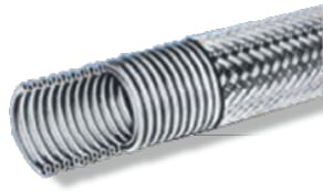
Made from stainless-steel strips, the inside tube of a flexible hose is annularly corrugated tube manufactured by continuously processing the material on a high-speed, automatic-forming machine. The geometry of the corrugations gives the flexible metal hose excellent hoop strength, providing superior resistance to collapse when exposed to high pressure. After the initial processing, the flexible hose is annealed in a furnace without oxidation to completely eliminate residual stresses. The outer covering is made from a stainless-steel wire braid which provides the necessary protection from abrasion (Figure 1).
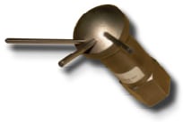
The burners in the cases descrbed here are combination oil- and gas-firing, which are designed to operate with both liquid and gas fuels. Fuel-gas burner tips (Figure 2) are made from high-temperature metal alloy casting, because they are typically exposed directly to the heat source (flame) in the radiant box of fired heaters. The burner components, including the burner tip, are designed in accordance with the minimum requirements as shown in API standard 560 (Fired Heaters for General Refinery Service).
The use of flexible hoses in burner systems also carries some limitations. Compared to rigid piping, flexible hoses (corrugated tube) are formed out of thin-walled tubing. One of the most serious drawbacks of flexible hose is that their thickness (0.26-mm) is not sufficient to withstand corrosion in cases where the hose is not completely chemically resistant to the media to which it will be exposed. Corrosion then becomes a serious concern, and engineers need to account for non-obvious sources of corrosive materials and various corrosion mechanisms.
Once corrosion is initiated, the life of corrugated flexible tube becomes very short. The use of corrosion-resistance charts published by manufacturers of piping components, such as pipe fittings, flanges and others, is not recommended for flexible metal hose because these other “regular” piping components generally have much heavier wall thicknesses than corrugated metal hose, and therefore may have allowable corrosion rates that would be unacceptable for the flexible hose.
Regarding cost comparisons between flexible hose and rigid piping — especially for 1-in. burner piping — the price of stainless-steel flexible hose is about twice that of carbon-steel rigid piping. However, the installation cost of the rigid piping is about three times higher than what is required for flexible hose, since the rigid piping requires special fit-up and welding. So although flexible hose may seem economically advantageous at the installation stage, the longer-term costs of maintenance and safety must be taken into account, especially if there is a possibility of corrosion.
Piping leaks cause a fire
The following is an account of a fire around the burner piping at a petroleum refinery, and of the subsequent investigation and failure analysis that identified dew-point corrosion as the major factor in the pipe’s failure and the resulting fire. The situation described here has parallels to other facilities using flexible hoses as burner piping.
During the start-up of a fired heater, right after a turnaround in a petroluem refinery, there was a severe fire around the burner piping that heavily damaged neighboring equipment and caused unscheduled downtime for a long period, mainly due to the fire damage of instrument cables. After putting out the fire, further investigation showed that the flexible hoses used for fuel gas were leaking. Similar to many refinery fires, the incident started with a single problem of piping leakage. Without an intermediate step, the pipe exploded and the fire spread to the rest of the main equipment, including the instrument cables.
The process details were as follows: operating fuel-gas pressure of 1.2–1.5 kg/cm2; operating fuel-gas temperature of between 30–60oC; fuel-gas composition of 69% H2, 10% ethane, 8% C3H8, and 13% other components, but no critical toxic components. The system was designed to operate with either oil or gas, but could not use both fuels simultaneously.
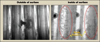
When investigators visually observed the flexible hose bellows (corrugated stainless-steel tube) for initial clues, they found many small pinholes, especially at the bottom section of the tube, as depicted in Figure 3. The pinholes are characteristic of pitting-type corrosion, where localized metal-thickness loss occurs, leaving pits. Detailed specifications of flexible hose and burner tips are described in Table 1. In addition to the pinholes on the bottom outside surface of the flexible tubes, other initial visual observations included the following:
| Table 1. Specifications of flexible hose and burner tip | |||
| Material | Specification | Remarks | |
| Flexible hose with AISI Type 304 wire braid | AISI Type 304 | Size 0.5 in., 0.26-mm thickness, AISI Type 304 strip annularly corrugated tube | See Fig. 1 |
| Burner tip | 300 series stainless steel | Casting (1,800°F resistant) | See Fig. 2 |
• Liquid stagnation marks were noticed at the bottom of the corrugated tube
• Severe thinning and pitting were noticed at the bottom area on the internal surface of the corrugated tube
• The region near the pits, which is thinned due to corrosion, showed layers of deposits over the surface
• The failed portion of the tubes contained pitting holes, which had perforated the tube initiating from the inside surface. The perforation made holes approx. 1–2 mm that were surrounded by thin pits, as depicted in Figure 3
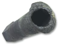
• The top part of the gas tip was melted out, and there was severe coke built-up inside of the gas tip as depicted in Figure 4
• Gas tip holes were melted, plugged and eroded
Regarding the melted fuel-gas tip and severely plugged gas-tip holes (Figure 4), investigators found that, upon reviewing the maintenance history, the fuel-gas burner tips had been frequently replaced during operation due to severe damage. In general, because burner tips are custom-designed in number, size and in the angle of the tip holes for specific applications (Figure 2), the damaged burner tip will result in undesired flame characteristics, including length and size, as well as low performance in operation, such as higher NOx emissions.
Failure analysis
Engineering failure analysis has two major objectives: to determine the failure mechanism and to determine the failure root cause. The failure mode is the basic material behavior that results in the failure, for example, pitting corrosion. The root cause is the fundamental condition or event that caused the failure, such as material defects, design problems and improper use. The present investigation of the failed flexible hoses considered several possible reasons for the tube failure. They include the following:
• The wrong material of construction was selected, or had an abnormal composition
• The flexible tube was installed improperly
• The corrugated flexible tube was damaged due to kinking or excessive bending
• A process upset occurred, where temperature or pressure were higher than the design conditions
• Corrosion due to a corrosive chemical species not related to the material of construction
The chemical composition of the corrugated tube was reviewed, and a metallurgical analysis conducted. The chemical analysis confirmed that the material of construction (MOC) of the flexible hose tube was Type 304 stainless steel, which is the correct MOC for the design fuel gas composition, and the failed tube satisfied the ASTM International specification for AISI Type 304 stainless steel. Also, no abnormalities were noticed in the tube metallurgy, so tube failure due to the wrong material of construction was ruled out. Similarly, there was no evidence of incorrect installation, such as kinking or twisting of the flexible hoses. In accordance with API RP535 (Burners for Fired Heaters in General Refinery Services), the flexible hoses were installed within their designed radius of curvature.
EDX and corrosion
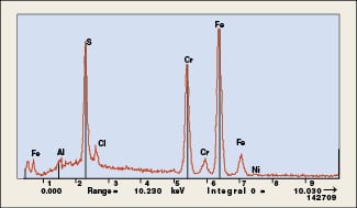
Attention then turned to corrosion as ultimate cause of the accident. Because the corroded pits were found on the corrugate tube, it was necessary to carry out EDX (energy-dispersive X-ray spectroscopy) in an effort to identify the component of corrosion from the deposit scale on the inside of the tube. EDX is an analytical technique used for the elemental analysis or chemical characterization of a sample. The EDX studies were carried out to determine the elemental compositions of the matrix and the deposits and scales on the failed tubes. The EDX profile (Figure 5) of the failed tube shows iron, sulfur and chromium in very high concentrations. The results of EDX studies indicate that there was substantial incorporation of sulfur compounds in the corrugated tube inside during operation. Sulfur and chloride helped cause the corrosion, while Cr, Fe, Ni resulted from the corrosion. The pitting corrosion is caused by the effects of sulfur and chloride, especially when they are present in hydrous solutions. Attack on the material is affected by chemical concentration, temperature and the type of material from which the corrugated tube is manufactured.
Stagnation of fuel gas condensate during heater operation may increase the corrosivity of the environment, and reduce stability of the protective surface films and increase susceptibility to metal loss. Most stainless steels form a protective film of stable oxides on the surface when exposed to oxygen gas. The rate of oxidation is dependent on temperature. At ambient temperatures, a thin film of oxide is formed on the stainless steel surface. In accordance with the corrosion resistance charts published by NACE (National Association of Corrosion Engineers), it is not recommended for Type 304 to be used with sulfuric acid and sulfurous acid.
A number of key findings arose from the EDX analysis, including a relatively large amount of sulfur, despite the fact that the fuel gas contains virtually no sulfur at all. This implies that the main cause of the corrosion may not be related to the fuel gas itself. The sulfur content in fuel gas is only 10 ppm, so the fuel-gas condensate is not likely to have caused the corrosion. Tube failure due to fuel gas was ruled out.
Dew-point corrosion
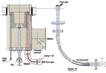
Given the evidence of sulfur from the EDX, the question becomes, what is the source of the sulfur? In approaching the corrosion issue, we must look into the fluegas side, as well as fuel gas itself, to find the source of the sulfur. It is crucial to understand the mechanism of fluegas acid dew-point corrosion. It is very important not to cool the fluegas below its acid dew point because the resulting liquid acid condensed from the fluegas can cause serious corrosion problems for the equipment. During oil firing, the gas burner is not in operation, however the gas guns are placed in the burner and the gas tips are exposed to the hot fluegas in the radiant box. One of the most striking features of this combustion process is that the fluegas penetrates through the idling fuel-gas tip holes, and collects inside of the corrugated tube.
To explain the fluegas flow mechanism, and why fluegas enters the burner gun, it is helpful to use Charles’ Law of gas volume — at constant pressure, the volume of a given mass of an ideal gas increases or decreases by the same factor as its temperature on the absolute temperature scale. The hot fluegas continuously flows into the burner gun and into the corrugated tube due to the gas-volume difference between the hot burner-tip area and cold flexible-hose area. Once the fluegas stays inside the corrugated tube, then the fluegas becomes condensate when the temperature drops below the dew point. The fuel oil contains sulfur at a concentration of 0.3 wt.%, and the combustion of fluegases may also contain small amounts of sulfur oxides in the form of gaseous sulfur dioxide (SO2) and gaseous sulfur trioxide (SO3). The gas-phase SO3 then combines the vapor phase H2O to form gas-phase sulfuric acid (H2SO4), and some of the SO2 in the fluegases will also combine with water vapor in the fluegases and form gas-phase sulfurous acid (H2SO3):
H2O + SO3 ⇒ H2SO4 (sulfuric acid)
H2O + SO2 ⇒ H2SO3 (sulfurous acid)
The collected fluegas (gaseous acid) in the flexible hose between the gas tip and the isolation valve will continuously condense into liquid acid, because the burner piping located outside the furnace cools down to atmospheric temperature, which is far below the sulfuric acid dew point of fluegas (about 120°C at 0.3 wt.% fuel oil, depending upon the concentration of sulfur trioxide and sulfur dioxide). Eventually, the liquid-phase sulfurous and sulfuric acids lead to severe corrosion.
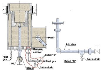
This explanation may be somewhat confusing, because it is generally thought that the amount of fluegas flowing through the small gas-tip holes is negligible. However, in actual field operation, especially during cold weather, we have observed more than 50 mL of condensate inside the 1-in. flexible hose when the flexible hose is dismantled after one week of operation with fuel-oil firing only (no fuel-gas firing). Therefore, there is no doubt that the failure was the result of corrosion by fluegas condensation (see Figure 6 Detail ‘A’ for illustration).
Burner tip plugging
Liquids, particulate matter, unsaturated hydrocarbons and H2S in fuel gas can cause most plugging problems. In order to identify the material causing the tip plugging, the fuel-gas analysis and the design review of the knockout drum that removes liquids from the fuel was carried out. However, there were no out-of-specification instances in the above-listed items. Nonetheless, the focus needed to be on the condensate from fluegas. It is important to recognize that the collected condensate will be carried over to the gas tip as soon as fuel gas is pressurized and serviced. Under continuous fuel-gas-firing operating conditions, this may not be a problem because the tips are cooled enough by the high-velocity fuel gases flowing through gas tips. Upon switching from oil firing to gas firing, the condensate, which stays inside of the flexible hose, will automatically be delivered to the hot gas tip. This will lead to abrupt evaporation of liquid inside of the hot gas tip, and then result in plugging due to hydrocarbon coke build up, and finally to melting of the gas tip. Overheating the burner tips can cause the carbon in the fuel to thermally crack, giving rise to severe coking inside the tips, which leads to plugging of the holes.
Recommendations
Considering the above, it is highly recommended that the fuel-gas piping for combination-type burners that could possibly have fluegas condensation be designed with rigid piping (size 1 in. Schedule 40: 3.4-mm thickness) instead of flexible hose. The rigid piping is about 13 times thicker than flexible bellows tubes, as depicted in Figure 7. In real-world industrial practice, little is known about corrosion failure of rigid burner piping that may experience dew-point corrosion from fluegas condensation. It is possible that the thicker-walled piping could prolong pipe lifetime.
For gas-firing burners, the use of rigid piping is also recommended in the case of intermittent gas-firing burners that use high-sulfur fuel gas. If the use of flexible hose is not avoidable, then the material of the bellows tube should be Inconel 625, which is properly resistant to sulfur corrosion, or stainless steel lined with PTFE (polytetrafluoroethylene) and flared-end fittings.
| Table 2. Recommendations in burner piping of oil-and-gas combination burner | |
| Burner piping specification | • Rigid piping is preferred rather than flexible hose in order to prevent fuel gas leak due to acid dew point corrosion of fluegas. • Low point drain with slope is preferred in order to prevent burner tip plugging due to liquid carryover. |
| Code (API RP535) | • The requirement for preventing “fluegas acid dew-point corrosion in burner piping” should be clearly specified. |
Periodic soap-bubble tests on the surface of the flexible hoses can eliminate the potential for accidental fires. Also, close visual monitoring can allow earlier identification of possible failures. During inspection, corrosion of a flexible corrugated metal hose can be spotted by looking for signs of chemical residue on the exterior of the assembly, or by pitting of the metal hose wall. The braid wires may become discolored from chemical attack and begin to fracture.
In order to prevent fuel-gas tip damage due to liquid carryover, a drain system at the nearest point from the burner gun should be provided at the lowest point of fuel-gas piping between the first block valve and burner tip (see Figure 7). Also, it is necessary that the activity of the liquid drain before gas firing should be strictly specified in the burner operation manual.
Considering the huge risk of damage by fire due to burner piping leakage, more consideration needs to be given to the revision of the code or specification. In case of the API RP535 2nd ed. (Burners for Fired Heater in General Refinery Services), it is highly recommended that the detail requirement for preventing “fluegas acid dew-point corrosion” should be clearly specified, in addition to the current mechanical requirement for flexible hoses (flexible hoses require special attention to avoid failure due to kinking).
References
1. American Petroleum Institute, Standard 560, Fired Heaters for General Refinery Service, 3rd ed., American Petroleum Institute, Washington, D.C.
2. Industrial Heating Equipment Assn., “IHEA Combustion Technology Manual,” 4th ed., Taylor Mill, Ky., 1988.
3. Marcus, Philippe, “Corrosion Mechanisms in Theory and Practices,” 3rd ed., CRC Press, Boca Raton, Fla., 2012.
4. Craig, Bruce D., “Handbook of Corrosion Data,” 2nd ed., ASM International, Materials Park, Ohio, 2002.
5. Young, John, Corrosion by Sulfur, Chapter 8, of “High-temperature Oxidation and Corrosion of Metals,” Elsevier Corrosion Series, Elsevier, Burlington, Mass., 2008.
Author

Hyunjin Yoon is a team leader for reliability engineering of stationary equipment at SK Innovation (110 Kosa-Dong, Nam-Ku, Ulsan, South Korea 680-130, Phone: 82-52-208-5340, Email: [email protected]). He received a B.S. in mechanical engineering from the Hanyang University in Korea, and an M.S. in materials science and engineering from Stanford University. He has over 25 years of petrochemical industry experience, including wide experience in fired-heater design, troubleshooting and maintenance. He has played significant roles with major companies in the development of maintenance procedures for various pieces of stationary equipment.
