Understanding how to size and select pressure-relief devices is key to ensuring the safety of your facility
Pressure-relief and pressure-regulating devices serve the critical purpose of protecting facilities, people and equipment from potentially harmful, even catastrophic overpressure situations. For this reason, it’s important to properly size and select this equipment to meet specific applications needs, as well as keep abreast of the latest technology advances that can help ensure the safety of your chemical process industries (CPI) facility.
Sizing and selection
Pressure-relief and pressure-regulating devices are by no means one size fits all, so sizing and selection is one of the most challenging aspects of ensuring safety in the plant, say the experts.
“There are north of 20 to 30 variables required to size and select pressure-relief valves, including system pressure, back pressure and set pressure,” explains Sean Croxford, business unit manager with Farris Engineering, a division of Curtiss-Wright (Brecksville, Ohio; www.cw-valvegroup.com/farris). “When considering the entire relief-system design and depending on the type of protected system, there could be more than a couple hundred variables to include in an evaluation. Focus must not be only on the most catastrophic scenario, but on all of the scenarios per OSHA 29 CFR 1910.119 requirements. All scenarios must be fully documented. Careful consideration should be given to document not only applicable scenarios, but non-applicable scenarios, as well.”
According to Robert Owens, general manager – pressure management with Proconex, Emerson Automation’s Local Business Partner serving the Mid-Atlantic Region (Royersford, Pa.; www.proconexdirect.com), customers should also be aware of the following considerations when searching for the best solution:
- Operating temperature. Can elastomer seats be used or are metal-to-metal seats required?
- Desired operating pressure. Will a spring-loaded valve work or will a pilot-operated relief valve be required?
- Environmental considerations. Is industry standard seat leakage acceptable?
- Inlet and discharge piping design. Does the design of the inlet piping create excessive line loss that can affect the operation of the valve? Does the discharge piping system create excessive backpressure during a relief event that will affect operation of the valve and de-rate its relief capacity?
- Required capacity. Does the required capacity necessitate more than one safety-relief device to safely protect the process?
Ken Kurko, director, process safety services with Fauske & Associates (Burr Ridge, Ill.; www.fauske.com), continues to explain the importance of these considerations. “The first step for our clients is deciding what overpressure scenario they want to protect the vessel against in order to determine how large the device needs to be, as well as how much flow area is required to vent the vapor, gas or liquid that is going to be relieved from the vessel. Once the proper size of the device is selected, there should be pressure drop evaluations performed on the piping leading into and out of the device. Regulations specify that the inlet pressure drop to a safety-relief valve must be less than 3% of the set pressure and, for conventional valves, the outlet pressure drop from the valve must be 10% less than the set pressure.”
Other considerations when dealing with the CPI, says Gabe Wood, manager, thermal hazards testing and consulting with Fauske, include what material is being vented to the environment, because the venting of many materials, as well as the amount vented, must be reported to environmental agencies. “Often, processors want to use valves because they reclose, which means less material is vented, but in potential chemical runaway situations, a rupture disk may be the better choice because it opens to remove as much reactive material as is possible from a process vessel. For reasons such as this, a process engineer must balance environmental issues with safety decisions.”
Also, runaway reactions are more likely to create two-phase flow, meaning a liquid and a gas may flow through the relief device at the same time, notes Benjamin Doup, senior nuclear and chemical engineer with Fauske. “In these potential situations, the critical velocity of the two-phase flow may necessitate an increase in the size of the relief device to prevent the vessel from being over pressurized.”
Chemical applications are among the most demanding relief scenarios because they often include exothermic or runaway reactions, so it is important to select the proper size and design. Fortunately, there are multiple industry resources to assist in the design and selection of safety relief systems. The most widely used resources, according to Owens, are American Petroleum Institute’s (API; Washington, D.C.; www.api.org) RP520 Parts 1 and 2. API Part 1 covers the types of safety relief devices, calculating for required relief capacities and sizing safety-relief devices. “It also has sample specification sheets that can assist the engineer in providing the complete information needed for a manufacturer to confirm sizing,” he says. API RP520 Part 2 covers installation of safety relief devices. Topics include location, use of isolation valves, discharge piping, reaction forces and maintenance.
In addition, chemical processors should use safety-relief devices that are certified by the American Society of Mechanical Engineers (ASME; New York, N.Y.; www.asme.org). “Safety relief devices used on ASME-coded pressure vessels must carry ASME certifications,” explains Owens. ASME-certified devices have gone through a certification process that includes audits of the manufacturer’s or assembler’s quality system and certification testing at either the National Board of Boiler Inspectors (NBBI; Columbus, Ohio; www.nationalboard.org) laboratory or another certified laboratory.
Also helpful are the software calculation tools available from most manufacturers, which help simplify the sizing and selection process, notes Curtiss-Wright’s Croxford. “The sizing tools are automated and simplify the selection and sizing process. However, because there are so many other variables to consider, selecting a vendor that offers engineering design services is helpful because they specialize in understanding relief-valve systems and how pressure-relief valves perform within them. They have a deeper understanding of things like process hydraulics, backpressure and other process conditions that might need to be factored into sizing.”
Pressure-Relief and Pressure-Regulating Devices: the basics
Pressure-relief and pressure-regulating devices are used to protect personnel and equipment from dangerous increases in pressure in a process. “Pressure-relief devices are used to protect against relief scenarios which include, but are not limited to, control valve failure, external fire, regulator failure, overfilling and exothermic reactions,” says Robert Owens, general manager – pressure management with Proconex, Emerson Automation’s Local Business Partner serving the Mid-Atlantic Region (Royersford, Pa.; www.proconexdirect.com). “They are used throughout a chemical processing plant on reactors, steam distribution systems, and utility services such as plant air or nitrogen, pump discharge and boilers.”
Safety-relief valves are available in two basic designs: direct spring loaded and pilot operated. Direct spring loaded valves use a spring to provide a closing force on the valve based upon a specified set pressure. Pilot operated relief valves use system pressure instead of a spring. Typically, direct spring safety relief valves should not be operated any higher than 90% of the stamped set pressure on the nameplate of the valve. By their design, pilot operated relief valves can operate much closer to set pressure, explains Owens. “In some applications, pilot-operated relief valves can operate up to 98% of the stamped set pressure,” he says.
Rupture disks are also commonly used in the chemical process industries (CPI). Unlike safety relief valves, rupture disks do not re-close after a release. “Depending on the design, rupture disks can be operated up to 95% of stamped burst pressure. Many chemical processing facilities use rupture disks to isolate safety-relief valves in order to eliminate seat leakage and to protect the valve internals from corrosive media,” says Owens.
Alan Wilson, senior field engineer and agency manager, with Oseco (Broken Arrow, Okla.; www.oseco.com) agrees that a combination of the two technologies is often recommended in the CPI. “You get the best of both worlds. When there’s an overpressure situation and the rupture disk bursts, the relief valve also opens to relieve any excess pressure and then closes, preventing the entire loss of what is inside the process from leaking out of the vessel,” he says.
The combination also serves to keep pressure-relief valves in good working order because without the disk, the valve may be exposed to corrosion and erosion from the process, which can cause pressure relief valves to malfunction, says Wilson. “The other advantage is, if you are running a process that is highly toxic or is being monitored by environmental agencies, the rupture disk prevents seat leakage of the pressure-relief valves, especially as you creep closer to set pressure,” he adds. “In addition, rupture disks can help extend intervals between pressure-relief valve maintenance and cleaning.”
Pressure-regulating valves are used to control either upstream pressure or downstream pressure by reducing or retaining line pressure in application. Pressure-retaining valves are used to maintain the line pressure to a set value on the valve inlet, while pressure reducing valves reduce the line pressure to a set value on the valve outlet, explains Jeffrey Sixsmith, product manager for valves and actuation with GF Piping Systems (Irvine, Calif.; www.gfps.com/us). ❑
Recent innovations
While the basic technology behind pressure-relief and pressure-regulating devices hasn’t changed much over the years, and most are currently able to attain the highest performance, manufacturers have been working on innovations that help overcome common challenges and further ensure safety.
“A lot of our customers face challenges when it comes to proper installation of rupture disks,” says Alan Wilson, senior field engineer and agency manager with Oseco (Broken Arrow, Okla.; www.oseco.com). “Installation errors, such as putting rupture disks in the wrong holder or putting the holder in upside down, are not uncommon and can lead to leakage. For this reason, we’ve started to focus on making them easy to install and ensuring that the devices will operate properly.”
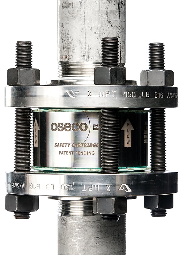
Oseco’s Safety Cartridge (Figure 1) is a result of these improvements, he says. The device provides a fully integrated holder disk in one hermetically sealed component designed to eliminate handling of the disc, protect the dome, reduce installation time and prevent leakage. The intuitive design shortens the learning curve and supports correct installation. The one-piece assembly also solves issues with leaking because it follows torque specifications of the gaskets, so the force is placed on the outlet rather than on the disk. Fugitive emissions are also eliminated because the electron-beam-welded design cannot leak outside of the piping and supports regulatory guidelines.

Figure 1. Oseco’s Safety Cartridge provides a fully integrated holder disk in one hermetically sealed component designed to eliminate handling of the disc, protect the dome, reduce installation time and prevent leakage
Oseco
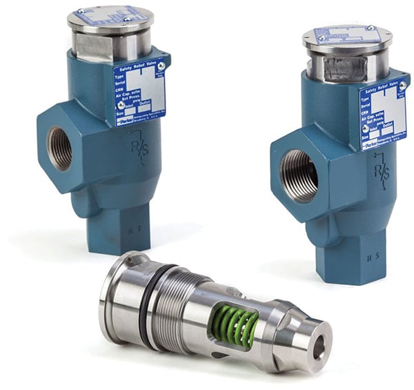
For its safety-relief valves, Parker Hannifin (Cleveland, Ohio; www.parker.com) also developed a cartridge system to simplify installation and maintenance. The company’s Cartridge Safety Relief Valves (CSRV) (Figure 2) are designed to offer the highest level of protection while maintaining easy serviceability. The device was designed from the company’s existing safety-relief valve housing, which allows for a simple and easy upgrade path to the new cartridge-based design. The cartridge-based design allows for replacement while the housing remains in the system. “It is required by code to replace safety relief valves every five years or after a release, so this type of periodic maintenance is greatly simplified with a cartridge base,” says Andrew Stock, product manager with Parker Hannifin’s Industrial Refrigeration Division. “It is a quick changeover that doesn’t require altering the piping of the system. Users simply unscrew the cartridge, replace it with a new one and put the changeover valve back in the right position. Instead of hours of work with a pipe fitter, this can be done in a matter of minutes with no special tools or changes to the piping system.”

Figure 2. Parker Hannifin’s Cartridge Safety Relief Valves, designed to offer the highest level of protection while maintaining easy serviceability, allow for a simple and easy upgrade path to the new cartridge-based design. The cartridge-based design allows for replacement while the housing remains in the system
Parker Hannifin
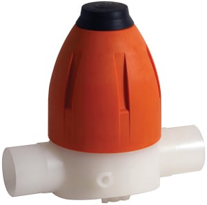
For its pressure-regulating valves, GF Piping Systems (Irvine, Calif.; www.gfps.com) is also working toward simplifying installation, as well as making their valves more compact and more reliable via the use of molded bodies and union connections. While most pressure-regulating valves offer threaded connections, union connections allow users to easily install and remove the valve from the system. The compact design allows installation even when space is limited and the integrated assembling aid enables direct assembly of the valves to mounting sets. “With this design, the entire inner workings are in a self-contained unit, called the cartridge, and the housing is the body. This allows users to easily take the valve out and exchange it with another so they can perform maintenance, reducing time,” notes Jeffrey Sixsmith, product manager for valves and actuation with GF Piping Systems. “In addition, the housing is interchangeable between pressure retaining and reducing valves, so it is only necessary to stock the valve cartridges. You can change the valves from downstream control to upstream control using the same housing.”
The recent approval of restricted lift options for pressure-relief valves under ASME Code Section VIII and API 526 has led Curtiss-Wright’s Farris Engineering division to offer restricted lift on its 2600 and 2600L Series API-type pressure relief valves. The restricted lift option is available on orifice sizes D-Z for compressible service for both new 2600 Series valves and as a retrofit option for Farris’ in-service valves. The benefit of using restricted lift, according to the company, is that operators can more closely match the pressure-relief valve’s flow capacity to the systems’ required capacity. Restricted lift can improve valve performance and stability, especially in larger orifice size valves. Pressure-relief valves with a restricted lift option are also a cost effective solution where pressure relief valves experience inlet pressure losses in excess of 3% of set pressure. “Restricted lift valves reduce the valve’s maximum relieving capacity, which reduces the frictional losses associated with piping hydraulics, as the piping losses are calculated based on the valve maximum relieving capacity,” explains Croxford.
Monitoring installed relief devices is another industry trend, says Proconex’s Owens. “The EPA [U.S. Environmental Protection Agency (Washington, D.C.; www.epa.gov)] and state departments of environmental protection are demanding that facilities report releases to flare or to the atmosphere. Reportable releases can result from safety-relief valves lifting to relieve an overpressure event or from leakage across the seat of the valve during normal operation,” he says.
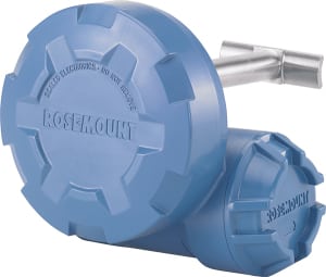
The monitoring technology that appears to be gaining traction is wireless acoustic monitoring, Owens says. “Acoustic monitors, such as the Rosemount 708 Wireless Acoustic Transmitter, can be attached to downstream piping without necessitating breaking the pipe or pipe modifications. These monitors will detect minute leakage and a pressure-relief event, as well as the length of that event, allowing chemical processors to easily calculate the amount of product that has been released.” Another benefit to the technology is that it can provide an early sign of problems with the valve, allowing the processor to quickly identify and fix the issue.

Figure 3. Working toward simplifying installation, as well as making their valves more compact and more reliable, GF Piping Systems developed molded bodies and union connections for their pressure regulating valve lines
GF Piping Systems

Figure 4. Rosemount 708 Wireless Acoustic Transmitter can be attached to downstream piping without necessitating breaking the pipe or making pipe modifications. These monitors will detect minute leakage and a pressure-relief event, as well as the length of that event, allowing chemical processors to easily calculate the amount of product that has been released
Emerson