To make the most of process control signals, signal integrity must be maintained from the process all the way to the instrumentation, making proper wiring essential
Despite a large uptick in the deployment of wireless networks in plant measurement and control applications, numerous hard-wired systems continue to be placed into service each day. Plant technicians still spend several hours on the phone or, more often now, virtual conferences, with instrument-and-control system suppliers in attempts to track down the seemingly inevitable signal gremlins that no one can quite pinpoint. Yet, the plant human-machine interface (HMI) proves that there is phantom noise, resulting in inaccurate control. The good news is that there are tried and proven wiring practices from experience with 4–20-mA signals that can preempt these sorts of mysteries — and the accompanying finger pointing between suppliers and end-users. Those finding themselves in the midst of such problems can use the same practices to rapidly track down root causes.
The need to accurately measure process variables and control process equipment is paramount in today’s automated facilities. Instrumentation forms the brains in modern automation plants, and its wiring and sensors are the nerves that connect the remote areas of processes to the brain. It controls and monitors the operation of the equipment in your plant. In many cases, the signals that are being monitored are in the millivolt range. To make the most of the control signals that are being read from the process, signal integrity must be maintained from the process all the way to the instrumentation.
Many times, shop managers don’t think twice about spending top dollar for quality instrumentation to run their processes, but little thought is given to the wiring carrying the signal from the process to those instruments. In new installations, the cost of wiring can be a significant portion of the instrumentation package.
If proper installation of the wiring is ignored, any gains one was trying to achieve by purchasing new instrumentation can be marginalized by unwanted noise in the signal wires. In existing installations where performance may have been compromised by noise, upgrading instruments may mask the problem to some extent if the instrument is of good quality, but it could be a disaster if a budget model is selected. Maintaining the integrity of the control signals should be a primary goal of any instrumentation installation.
The industrial environment
Often, instrumentation is in the field next to an oven, another piece of equipment or, at least, somewhere on the plant floor. A reality that makes these areas a problem is the harsh electrical environment to which equipment located there is exposed. Unfortunately, this is the area where process variable measurements must be made. The process sensors and their wiring are most likely near heavy electrical equipment or motor contactors. They could even be exposed to static discharge from welding equipment. Many times, field wiring can run several hundred feet. Such long runs increase the likelihood that electrical interference could affect the signal. Typically, the control room is much kinder to control signals, but the high concentration of computers, two-way radios and other electronic equipment does provide opportunities to degrade signal quality.
There are many pieces of equipment and natural phenomena that can interfere with measurement signals. Equipment can create an electronic hazard for the instrumentation installed in the environment and the signals that pass through it. Since this environmental hazard typically cannot be eliminated, the effects on instrumentation must be understood so that they can be isolated and either removed or, at least, minimized. It is well understood how audio signals in high-fidelity equipment must be cared for to achieve the best sound quality — process instrumentation is no different. By understanding the ways that noise affects your control system, you can take the necessary steps to avoid these problems in your system.
Ensuring signal quality
The easiest way to ensure good signal integrity is to employ signal conditioners. Signal conditioners play an important part in instrumentation installations by ensuring that the signals measured by sensors in the field are transmitted to the control instruments representing the same conditions as were measured in the process. The long distances a signal must travel between the process and the control instrumentation offer ample opportunities for electromagnetic interference.
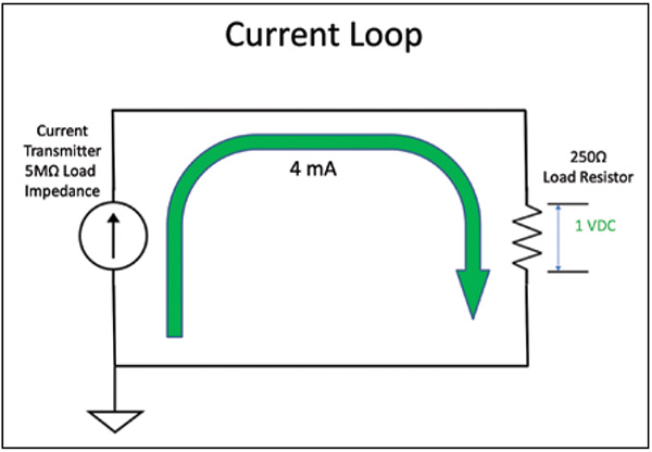
Signal conditioners provide two primary functions: maintaining signal integrity and signal isolation. Even though a single instrument can provide both functions, there are distinct and individual benefits that each one provides. The most common use of a signal conditioner is signal conversion. The most common conversion, even in today’s digital age, is to change a process signal from its original form and transmit it as an electrical signal over 4 to 20 milliamps (mA). A 4–20-mA current loop is a very robust carrier signal that is virtually impervious to noise (Figure 1). It has traditionally been the preferred method of signal transmission over long distances. Why does a 4–20-mA loop have such good noise immunity? It has to do with the transmitter.

FIGURE 1. A 4–20-mA current loop is a very robust carrier signal
All the resistive components in a circuit drop voltage in proportion to their part of the total resistance in the circuit. The more resistance a loop component has, the more voltage it will drop in the circuit — that’s Ohm’s law. Every current transmitter has some output resistance that contributes to the circuit. In proportion to the loop resistance, a transmitter’s input resistance, also commonly known as input impedance, can almost be considered as infinite. A transmitter’s typical output resistance could be between 3 and 5 meg ohms (MΩ), whereas the loop resistor is fixed at 250 ohms (Ω). Under normal conditions, the transmitter acts as a current source. Its resistance is not considered when dropping voltage.
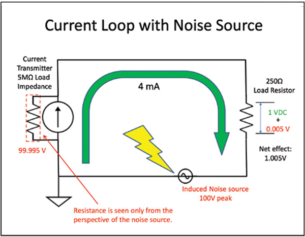
When an additional voltage source — such as unexpected noise — is introduced to the loop, the voltage is dropped across each of the resistors in the loop in proportion to its magnitude. If we remember the superposition theorem, the 5-MΩ resistance of the transmitter is no longer a current source, but a resistive load on the circuit with respect to the noise. The signal conditioner becomes a passive component in the circuit and absorbs most of the noise voltage with its 5-MΩ load — whereas the 250-Ω resistor on the receiving device receives only a tiny fraction. For example, if the noise voltage source induced a voltage of 100 volts, Ohm’s law would dictate that the signal conditioner would absorb 99.995 volts, whereas the control instrument will receive 5 millivolts (Figure 2). This is 1/200th of the 1-volt minimum that can be measured across the 250-Ω resistor on a 4–20-mA loop. This demonstrates one reason that converting transmission signals to 4–20 mA is a very good way to minimize noise in process control signals.

FIGURE 2. Even induced noise has a small effect in the loop
Wiring for signal integrity
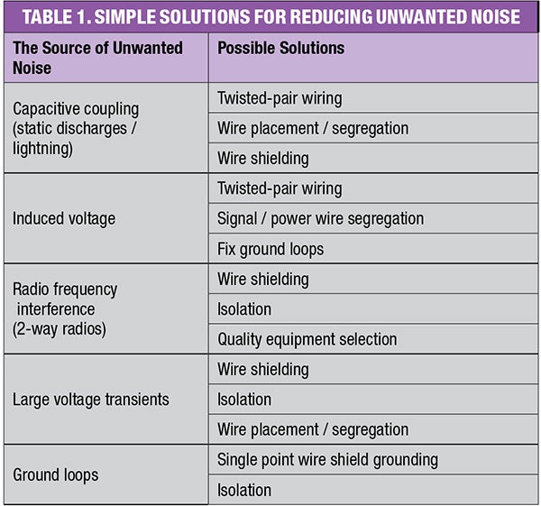
Signal integrity can be affected by wiring and shielding practices (Table 1). Wiring your process using twisted-pair cabling provides a significant level of protection from noise that may be coming from outside of the process. In this type of wiring, a pair of conductors in the same circuit is twisted together for the purpose of canceling out external electromagnetic interference. Since noise that is picked up by the wire along its path to the control panel affects both wires equally but oppositely, a good control device can reject the noise and recover the signal fully. This is called common mode rejection.

It is tempting to run all the wiring through a single conduit. The best advice in this situation would be, “Don’t do it!” This practice is an open invitation to additional troubles and sorrows. The magnetic coupling or induced voltages caused by the proximity of high voltage and currents next to your signal wires can induce some very high voltages on them. These voltages, at a minimum, could interfere with your process and, at a maximum, damage the inputs on your instrumentation. Most signal conditioners have input circuitry designed to prevent damage due to high transients. While your digital recorder is charting chaos, at least you won’t have to worry about replacing the entire instrument.
Ground loops. A ground loop is the most common noise problem in large-scale electrical systems. Ground loops stem from poor grounding practices. It is a major misconception that earth ground at one location contains the same voltage potential as earth ground at another location. Ground is an often-misunderstood electrical concept. The ground potential where you are currently located can be several volts above or below the ground potential in another part of the building. A nearby lightning strike could cause this potential to jump several hundred to thousands of volts.
If your instrumentation is grounded in separate locations in your facility where these ground potentials do exist, you could very easily be vulnerable to a ground loop if your wiring does not employ some type of isolation. Just the noise caused by a ground loop can wreak havoc on your system. There is also the issue of the induced voltages they create as they travel near and on signal wires. A common sign that a ground loop exists is the presence of induced 60-Hz power-line noise on the circuit. That can be easily measured with a voltmeter.
One way to eliminate ground loops is to employ a single ground concept where no ground loops can be created. All circuit grounds are returned to a common point. This is often done through bonding and the use of bus bars to carry all the ground signals to a single point. In many facilities, this may not be practical due to the physical size of the operation, and this is where the use of a signal conditioner designed for isolation comes into play.
An isolator is one of the easiest ways to eliminate a ground loop problem. In its simplest terms, isolation interrupts current flow between the different potentials in the grounds. This is accomplished by inserting an electrical or electronic device, such as a transformer or a signal conditioner, to break the physical connection between the two grounds. While the isolator interrupts the ground loop circuit, it allows the desired control signal to be passed through unencumbered. Isolation is a very cost-effective method for removing noise and transients due to ground loops.
Lightning. One lightning strike in proximity to your process could do considerable damage to your process equipment. The discharge from an indirect strike could put several thousand volts and high current on your power and signal wires. Typically, the further the sensor and instrument are apart and the longer the wiring runs connecting the two, the greater the chance of experiencing capacitive coupling from a lightning strike — and the higher the voltages and currents are.
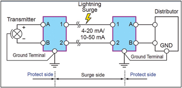
In situations where the electronic equipment narrowly escapes destruction, its circuits may become intermittent, or its performance may begin to deteriorate. A lightning arrester is a type of signal conditioner that is used to divert induced voltages that may be large enough to damage instrumentation. Lightning arrestors, when properly installed, redirect damaging surges to ground where they belong (Figure 3). With the capability to withstand 10,000 volts and up to 5,000 amperes you will not be left with the unpleasant task of replacing equipment after a storm.

FIGURE 3. This diagram shows the proper positioning of a lightning arrestor
At the heart of it all, an arrester is a switch that diverts high voltages and currents to a path to ground. There are many technologies that make up this type of switch, but a very common one is a metal oxide varistor (MOV). A MOV is a semiconductor that is sensitive to voltage. At normal operating voltages, the MOV acts as an insulator and will not conduct current. At higher threshold voltages, it responds like a conductor. This threshold voltage is determined by a doping process during the manufacturing process.
Modern instrumentation uses a wide variety of sensor inputs with varying voltage input levels. The use of a general-purpose lightning arrester would provide some protection, but it is not optimal. Arrestors are designed to work specifically with the particular input signals that are needed with their voltage requirements taken into account. The operating requirements for protecting an instrument’s power circuits would be different from those protecting its thermocouple input or its Ethernet IP connection. Selecting the proper arrestor ensures signal integrity and solid protection for the instrument are maintained.
Final thoughts
The probes, sensors and instrumentation designed to operate your processes for peak performance are often undermined by even the smallest amount of electrical interference. Devising and implementing a strategy to deal with environmental noise will make the difference between a good process and an exceptional one. Signal conditioners comprise that last step that allows an operator to provide the very best in quality and squeeze every bit of performance out of a system in which you have invested so heavily. ■
Edited by Dorothy Lozowski
Acknowledgement
All figures were supplied courtesy of Yokogawa
Author
 Clayton Wilson is a control products specialist at Yokogawa (2 Dart Road, Newnan, GA 30265; Email: [email protected]). Wilson has been with Yokogawa for over 20 years, and is an expert in process control and automation, specializing in discrete control applications in many industries. He manages Yokogawa’s lines of loop controllers, PLCs and signal conditioners in North America. He also helps direct future product development, making Yokogawa’s instrumentation more applicable and easier to use.